
what is a case drain on a hydraulic pump free sample
A case drain is a specific component of a hydraulic system, its objective is to extend the life of a system and reduce time spent on repairs and maintenance.An unrestricted case-drain line is essential on a piston-type hydraulic motor, whether it has axial, radial or bent-axis design. Most skid steers rely on hydraulic systems to power their front loading arms.
Sometimes referred to as a ‘third line’,a case drain drains back the oil which has leaked past the primary seal, and in doing so, prevents pressure from building up against the outer seal.This oil is then returned to the tank or reservoir.
A case drain will have an in-line case drain filter to prevent contaminants from travelling from the hydraulic motor to the tank. Operating a skid steer without a case drain line could result in a full system failure as the shaft seal will be irreparably blown out, if not installed properly your hydraulic line will not work and in worst cases become damaged beyond repair.
A good case drain makes your hydraulic system more energy efficient and lowers the pressure on the tank, good general maintenance of your hydraulic system results in longer durability for your skid steer and attachments.
A case drain is made up of multiple elements whose materials vary, it’s important to know how to remove and disassemble the case drain in order to understand its function and materials. A case drain filter is contained within an aluminum canister.
To remove the filter make sure to plug the drain lines to avoid losing hydraulic fluid or introducing contamination into the system. Simply unscrew the hex nut to access the filter element.
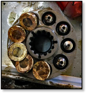
You may be surprised to find that case drain filters are made from a metal, sintered bronze to be specific. To the naked eye, the sintered bronze looks like one solid piece of metal but is actually thousands of bronze spheres that have been sintered together. Sintering is a heat treatment, like welding or soldering, that imparts strength and integrity to a ‘powdered’ material.
Sintering can determine a filter’s porosity which affects what goes through the filter and what doesn’t. Once sintered, the filter is now porous enough to allow hydraulic fluid to flow through it, yet remains dense enough to capture contaminants like metal and rubber debris which will eventually lead to a total system failure if left unmaintained.
Filters in a hydraulic system maintain fluid cleanliness at a level that maximizes component life. The appropriate cleanliness level is based on factors such as operating pressure and the internal clearances of components within a system.
If your case drain filter is blocked, then the hydraulic pressure of the motor will increase severely which will eventually lead to a myriad of mechanical and hydraulic issues and even a total system failure. Seals can be blown allowing hydraulic fluid and lubricant to leak out and also allowing contaminants to make their way into the skid steer and damage it irreparably.
If the filter in your case drain is no longer bronze in colour and looks mucky or dirty we suggest that you replace it. If your case drain is blocked then its worth dissembling the other filters and drain on the hydraulic system to ensure they have remained clean. It’s highly discouraged to attempt to clean your case drain or its filter.
Even if you had power tools or a heavy duty wire brush you will only move more trapped solids into the filter, clogging it even further. Case drain replacements are cheap when compared to replacing your whole final drive. Case drain maintenance is a key part of maintaining the life of your skid steer, and is often overlooked.
The main disadvantage of installing a filter on your hydraulics system is that back pressure created by the filter can cause total system failure caused by excessive pressure on the case drain if installed improperly
In some cases, case drains are considered optional. The case drain line is for low volume flow to the tank. In theory, by installing a high-pressure shaft seal and two check valves then internal leakage is technically drained into the return line, which is the usual function of a case line.
It has generally been found that systems without case drains often result in failure due to shaft seal leaks. Case drain line installation can be tedious but will eradicate any problem relating to shaft seal leakage.
Oftentimes, if a vehicle doesn’t already have a case drain line fitted, the manufacturer will not necessarily outline the need for hydraulic fluid to be returned to the tank. If you want optimum reliability from your tank and hydraulics then fitting a case drain line is the way to go.
Case drain lines are a very specific component, its use is debated among hydraulics experts - some say you need a case drain and others suggest you don’t. Ultimately, understanding how a case drain works is fundamental to upholding your machines maintenance and making sure that your tools last for a long time.
Many system failures in hydraulics are caused by leaks from the tank. It’s important not to neglect your hydraulics system as it could put you, or your workers, at risk.
Once you know how case drain filters work and what their function is within the hydraulic system of a skid steer, then you can visit your mechanical professional and ask for their opinion on whether you need to install a case filter on your skid steer or not.

www.powermotiontech.com is using a security service for protection against online attacks. An action has triggered the service and blocked your request.
Please try again in a few minutes. If the issue persist, please contact the site owner for further assistance. Reference ID IP Address Date and Time 8bf2006c85a66667641f5dd58dcb3d35 63.210.148.230 03/07/2023 08:41 AM UTC

One way to troubleshoot a final drive that seems weak is to take a look at the rate of flow from the case drain line. In this Shop Talk Blog post, we are going to review the purpose of a case drain line, look at what case drain flow can tell us about a final drive, and then discuss how to estimate the case drain flow. We"ll finish up by looking at how to evaluate the case drain flow to determine if the problem is your final drive.
When a final drive is damaged or badly worn, however, there will be more internal leakage. This excessive leakage will negatively impact the performance of the final drive and can be the cause of a lack of power. If there is too much leakage, it can be detected by monitoring the flow from the case drain line.
If the rate of case drain flow is greater than it should be, then there is a good probability that you have a problem with that final drive. Examples of too much case drain flow would be flow that is greater on the “bad” side than the “good” side, more than what the manufacturer specifies, or more than a very slow rate of flow). If your final drive"s case drain flow is too much, it should be serviced before things get any worse. On the other hand, if the case drain flow is within normal parameters, then the problem is probably not going to be your final drive and you need to keep investigating.
Investing the case drain flow from a final drive or travel motor can help when troubleshooting what seems to be a weak final drive or travel motor. Just keep in mind that it"s important to investigate all the possibilities before deciding the cause is your final drive motor.
is your partner in providing new or remanufactured final drive hydraulic motors from a single mini-excavator to a fleet of heavy equipment. Call today so we can find the right final drive or hydraulic component for you, or check out our online store to.

This article is based on a basic circuit with single hydraulic internal gear motor. More complex circuits with multiple motors can have different solutions. Collaborate with your motor supplier for the best results for your particular design.
Background: Hydraulic motors have a volumetric efficiency of 90-98%. That means 2 - 10% of the flow entering the motor leaks internally into the case. This is intentional and vital for internal lubrication and clearance between mating pieces.If not allowed to escape, that leakage can build pressure inside the pump case, causing seal leaks or worse, cracks in the cast iron case. The main purpose of a case drain is to allow the internal leakage to escape, but there are other benefits too.
Alternatives: The motor below has a clever solution making the case drain "optional". Two smaller plugs on the rear of this internal gear motor are for check valves.
In the absence of a case drain line, these check valves allow fluid in the case to enter the low-pressure fluid stream. This allows leaked fluid and contamination to exit the motor via the drain line. That might explain why you have seen some hydraulic motors without case drains. However, in a reversing application, that heat and contamination returns to the motor when the direction is reversed.
With a case drain vented to tank, heat and contamination are sent to the reservoir, extending motor life. Even if the case drain port is located on the bottom of the motor, the case will remain filled if the reservoir is above the motor.
“I tried one afternoon and evening to determine what was wrong with a hydrostatic transmission by monitoring case drain flow. I was confused by the readings I was seeing. There was a flow meter in the transmission pump outlet and another in its case drain that always showed charge pump flow, even though the motor was bypassing profusely. The motor case drain went through the transmission pump case to tank.”
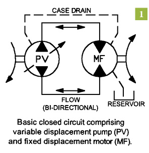
Recall that a hydrostatic transmission consists of a variable-displacement pump and a fixed or variable displacement motor, operating together in a closed circuit. In a closed circuit, fluid from the motor outlet flows directly to the pump inlet, without returning to the tank.
As well as being variable, the output of the transmission pump can be reversed, so that both the direction and speed of motor rotation are controlled from within the pump. This eliminates the need for directional and flow (speed) control valves in the circuit.
Because the pump and motor leak internally, which allows fluid to escape from the transmission circuit and drain back to tank, a fixed-displacement pump called a charge pump is used to ensure that the circuit remains full of fluid during normal operation. The charge pump is normally installed on the back of the transmission pump and has an output of at least 20% of the transmission pump’s output.
In practice, the charge pump not only keeps the transmission circuit full of fluid, it pressurizes it to between 110 and 360 PSI, depending on the transmission manufacturer. A simple charge pressure circuit comprises the charge pump, a relief valve and two check valves, through which the charge pump can replenish the transmission circuit. Once the circuit is charged to the pressure setting of the relief valve, the flow from the charge pump passes over the relief valve, through the case of the pump or motor or both, and back to tank.
When a pump or motor is worn or damaged, internal leakage increases and therefore the flow available to do useful work decreases. This means that the condition of a pump or motor can be determined by measuring the flow from its case drain line (internal leakage) and expressing it as a percentage of its theoretical or design flow.
When applying this technique to a hydrostatic transmission, charge pump flow must be considered. In most transmissions, the charge pump relief valve dumps into the case of either the pump or the motor. This means that in the circuit described by our reader, where the motor case drain flushed through the transmission pump case to tank, you would expect to see the flow meter in the transmission pump case drain line reading design charge pump flow. Here’s why:
Say charge pump flow was 10 GPM, of which 4 GPM was leaking out of the loop through the motor’s internals (case drain) and 2 GPM was leaking out of the loop through the pump’s internals. The balance of 4 GPM must therefore be going over the charge relief – but still ends up in either the pump or motor case, depending on the location of the relief valve. In this particular circuit, because the motor case drain flushed through the transmission pump case to tank, you would expect to see the flow meter in the transmission pump case drain line reading the sum of these three flows (10 GPM).
Before any meaningful conclusions can be drawn, the case in which the charge pump relief is dumping (motor or pump) must be determined and the two case drain lines (motor and pump) must be isolated from each other. If the charge relief dumps into the case of the pump, then it is possible to determine the condition of the motor by measuring its case drain flow, but not the pump. If the charge relief dumps into the case of the motor, then it is possible to determine the condition of the pump by measuring its case drain flow, but not the motor.
It is not possible to determine the condition of the component that has the charge relief valve dumping into it because there is no way of telling what proportion of the total case drain flow is due to internal leakage – unless of course the charge relief can be dumped externally while the test is conducted. While it is possible to do this on some transmissions, it’s not an easy or simple exercise.
Bottom line: using case drain flows to determine the condition of the components of a hydrostatic transmission, without thoroughly understanding the configuration of closed circuits, can result in incorrect conclusions and the costly change-out of serviceable components. And to discover six other costly mistakes you want to be sure to avoid with your hydraulic equipment, get “Six Costly Mistakes Most Hydraulics Users Make… And How You Can Avoid Them!” available for FREE download here.

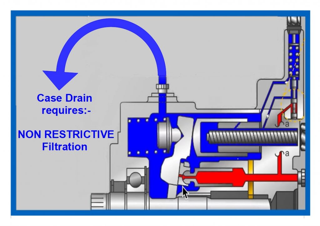
By installing a high-pressure shaft seal and two check valves as shown in the schematic diagram inset above, internal leakage is drained via the return line–something that’s not acceptable for a piston motor or pump!
So the presence of a high pressure shaft seal and check valves renders a dedicated external drain line optional. But not if reliability is the primary concern. Here’s one application example from the ‘coal face’:
“Part of a design modification we carried out to our fleet of drilling rigs required two, low speed, high torque (gerotor) motors being installed on the front of the drilling rig to turn a shaft that housed wire rope brushes to clean the spoil from the drill string. The early design was without case drains because the motors did not require it according to the specification. However after several failed motors due to leaking shaft seals, we installed external case drain lines. It meant quite a bit of extra work and materials (hoses, brackets, fittings etc.) to return the drain back to tank but since then the problem has been eliminated.”
This issue is one of many apparent conflicts in hydraulics between what is OK to do-according to the component manufacturer, and what is best for optimum reliability. Of course, there will always be exceptions to the rule. You may have a gerotor motor without an external drain line that has never leaked and doesn’t look likely to (and this is most probably because the hydraulic system it’s installed on has a low and stable return line pressure).
In other words, not installing a case drain line, even when it’s optional, can turn out to be a costly mistake. And to discover six other costly mistakes you want to be sure to avoid with your hydraulic equipment, get “Six Costly Mistakes Most Hydraulics Users Make… And How You Can Avoid Them!” available for FREE download here.

Often in hydraulic systems, hydraulic motors and pumps run case drain hoses. The reason for this is to drain excess internal oil leakage from the motor. This is certainly critical in a piston motor and pump as the pistons have some internal leakage as they are actually just metal on metal. If no case drain hose is installed then the result will be, at the least, a blown shaft seal, and at worst, a split or damaged housing.
With gear pumps the leakage drains back into the suction hose internally, so no case drain is required. With gear motors and geroller/geroter motors, the oil can drain into the outlet port, however, that means that the oil pressure in the outlet port must not exceed the pressure rating of the seal. If it does, then a case drain needs to be installed. This will then usually mean you can run motors in series without damaging the motor.
If you require assistance with your hydraulic system, motors, pumps, hoses, seals, case drain, oil, lubricants or anything else for that matter, please give us a call on (03) 5382 0574 or call in and see us at Horsham Hydraulics, 84 GolfCourse

Mid MichiganWhat is a case drain on a vacuum planter? We are converting our Kinze planter to v-sets. I have a dump valve on the tractor already, will that work for the return on the fan. Thanks

The system has three separate circuits, each with an axial-piston pump and a common reservoir. Case drain filtration was included to reduce the possibility of cross-contamination if a failure occured. The pump manufacturer led me to believe that although it isn’t the norm, if the pressure drop across the filter is kept to less than 30 PSI it will be all right. This forces filter maintenance.
Filters in a hydraulic system maintain fluid cleanliness at a level that maximizes component life. The appropriate cleanliness level is based on factors such as operating pressure and the internal clearances of components within a system.
Given that the objective of this process is to extend the service life of components in a system, it is imperative to understand that some filter locations can have the opposite effect.
The rationale for installing filters in piston pump and motor case drain lines is similar to the rationale for locating filtering media in the return line, meaning; if the reservoir and the fluid it contains start out clean and all air entering the reservoir and returning fluid is adequately filtered, fluid cleanliness will be maintained.
The main disadvantage of installing filters on piston pump or motor case drain lines is that the back pressure created by the element can cause failures. Drain line filters can cause excessive case pressure, resulting in seal failure and mechanical damage.
High case pressure results in excessive load on the lip of the shaft seal. This causes the seal lip to wear a groove in the shaft, eventually resulting in leakage past the seal. If case pressure exceeds the shaft seal’s design limits, instantaneous failure can occur. The subsequent loss of oil from the case may result in damage through inadequate lubrication.
The effect of high case pressure on axial piston pumps is similar to excessive vacuum at the pump inlet. Both conditions put the piston-ball and slipper-pad socket in tension during inlet (Figure 1). This causes buckling of the piston retaining plate and/or separation of the slipper from the piston, resulting in catastrophic failure.
High case pressure can cause the pistons of radial piston motors to be lifted off the cam. This occurs in operation during the outlet cycle. The pistons are then hammered back onto the cam during inlet, destroying the motor.
If residual case pressure remains high when the motor is stopped, loss of contact between the pistons and cam allows the motor to freewheel, resulting in uncontrolled machine movement.
I recently witnessed a situation where these problems occurred. I was asked to locate a replacement for a radial piston motor no longer in production. The motor in question was powering a winch on a barge working in an offshore oilfield. The situation was urgent because the downtime was costing the company $40,000 per day. When I inquired about the nature of the failure of the original motor, he reported the following symptoms:
On-site personnel had torn down the motor and sent photos back to the company’s onshore office. The photos of the motor internals showed no obvious failure, confirming my suspicions. I explained that the symptoms described were consistent with high case pressure, most likely as a result of a blocked or restricted case drain line. I later learned that a technician, who had recently completed a contamination control course, connected the motor case drain line back to the tank through the system’s return filter.
To avoid these problems, piston pump and motor case drain lines should be returned to the reservoir through dedicated penetrations. These penetrations must be higher than the unit’s case port and be connected to a drop-pipe inside the reservoir that extends below minimum fluid level.
Due to the reasons above, filters are not recommended on case drain lines. While this does allow a small percentage of fluid to return to the reservoir unfiltered, in most applications the contamination risk is low and can be effectively managed using oil analysis and other condition-based maintenance techniques.
The primary objective of contamination control is extending the service life of hydraulic components. Unfortunately, case drain filters can reduce the service life of piston pumps and motors, making their installation in pursuit of this objective a paradox.
Effective contamination control is achievable using alternative filter locations that do not compromise component reliability. However, if case drain filters are included in a system, precautions must be taken to ensure that damage is not caused to the components they were installed to protect.
If a filter is fitted to a piston pump or motor drain line, I recommend a 125-micron screen, grossly oversized for the maximum expected flow rate to ensure that pressure drop is minimized, even under the most adverse conditions.
The filter housing must incorporate a bypass valve with an opening pressure lower than the maximum allowable case pressure for the particular component (typically 5 to 15 PSIG). Installing a gauge or transducer upstream of the filter for monitoring case pressure is also advisable.
Brendan Casey has more than 20 years experience in the maintenance, repair and overhaul of mobile and industrial equipment. For more information on reducing the operating cost and increasing the...
This application relates to motor assemblies generally and, in particular, to hydraulic motor assemblies intended for use in driving a vehicle or other apparatus, such as a seed planting mechanism, a powered implement or a walk-behind machine such as a mower or snow thrower, for example.
An improved hydraulic motor assembly is disclosed herein. One or more hydraulic motor assemblies can be mounted on a vehicle or other powered equipment to drive, for example, one or more wheels, implements or shafts. A speed sensor can be incorporated in the hydraulic motor assembly to provide operational feedback to an electronic controller that precisely regulates the motor assembly"s output via direct control of a hydraulic pump in fluid communication with the hydraulic motor assembly.
A hydraulic motor assembly generally requires a case drain to remove the volume of fluid losses from the hydraulic motor that accumulate in the motor chamber. To eliminate the need for additional structure, such as additional hydraulic line and case drain port, an internal case drain may be provided. This can be a particular advantage when the hydraulic motor assembly is distant from its corresponding pump as in the case of an agricultural seed planter.
A better understanding of the objects, advantages, features, properties and relationships of the invention will be obtained from the following detailed description and accompanying drawings which set forth illustrative embodiments that are indicative of the various ways in which the principles of the invention may be employed.
FIG. 1 is a perspective view of a first embodiment of a hydraulic motor assembly with speed sensor in accordance with the principles of the invention.
FIG. 4 is a perspective view of a second embodiment of a hydraulic motor assembly with speed sensor in accordance with the principles of the invention.
The description that follows describes, illustrates and exemplifies one or more embodiments of the present invention in accordance with its principles. This description is not provided to limit the invention to the embodiments described herein, but rather to explain and teach the principles of the invention in order to enable one of ordinary skill in the art to understand these principles and, with that understanding, be able to apply them to practice not only the embodiments described herein, but also other embodiments that may come to mind in accordance with these principles. The scope of the present invention is intended to cover all such embodiments that may fall within the scope of the appended claims, either literally or under the doctrine of equivalents.
It should be noted that in the description and drawings, like or substantially similar elements may be labeled with the same reference numerals. However, sometimes these elements may be labeled with differing numbers, such as, for example, in cases where such labeling facilitates a more clear description. Additionally, the drawings set forth herein are not necessarily drawn to scale, and in some instances proportions may have been exaggerated to more clearly depict certain features. As stated above, the present specification is intended to be taken as a whole and interpreted in accordance with the principles of the present invention as taught herein and understood by one of ordinary skill in the art.
Referring to FIGS. 1-3, a first embodiment of a hydraulic motor assembly 10 of the present invention includes a gear assembly 20 housed within a first volume or sump, namely gear chamber 12 that is formed by joining gear housing 22 and main housing 40. Hydraulic motor assembly 10 also includes a motor 50 housed within a second volume or sump, namely motor chamber 14 that is formed by joining motor housing 60 and main housing 40. These two volumes can be hydraulically separate or in fluid communication with one another. In the illustrated first embodiment of hydraulic motor assembly 10, there is no fluid passage formed in main housing 40 to connect the first volume (gear chamber 12) to the second volume (motor chamber 14). In this instance, motor chamber 14 is sealed off from gear chamber 12 by a pressure seal (not shown) through which motor shaft 56 passes from one chamber to the next. A result of separating gear chamber 12 from motor chamber 14 is less wear on motor running surface 60adue to reduced contamination of the hydraulic fluid driving motor 50. A fluid passage between gear chamber 12 and motor chamber 14 can be added, if desired, and fluid can be filtered in a known manner, if deemed necessary or desirable for a particular hydraulic system configuration.
A gear assembly 20, depicted herein as a three-stage reduction assembly comprising a pinion gear, two combination gears, and a spur gear concentric with and engaged to an output shaft, can consist of one or more reduction stages depending on the particular vehicle or apparatus application. The various gears and shafts depicted herein can be supported in the housings in various ways known in the art. The gear assembly 20 initiates with pinion gear 21, which is driven by an end of motor shaft 56. Gear assembly 20 terminates with concentric drive gear 32 for driving output shaft 24 via the mating of splines 32aand 24a. Output shaft 24 is depicted as a tubular, hex cross-sectioned, output shaft and is configured as a through-shaft in hydraulic motor assembly 10, being accessible at each end through corresponding openings in gear housing 22 and main housing 40. Output shaft 24 includes hex mating surface 24bwhich is shaped to engage a correspondingly shaped shaft or axle (not shown). Gear assembly 20, as configured, serves to reduce the output speed of, and increase the torque to, output shaft 24.
Rotational drive is provided to gear assembly 20 by means of a hydraulic motor 50, depicted herein as comprising axial piston cylinder block 52 disposed on the running surface 60a, also known as a hydraulic mounting surface, that is formed on motor housing 60. It will be understood that a valve plate could optionally be used if necessary between cylinder block 52 and running surface 60a. Motor housing 60 includes hydraulic passages 61aand 61bformed therein to provide fluid communication between the kidney ports 68aand 68b, respectively, of running surface 60aand hydraulic ports 62aand 62b, respectively, on the exterior of motor housing 60. As shown in FIG. 8, hydraulic ports 62aand 62bin turn provide fluid communication with additional elements of a hydraulic circuit, namely pump 11. Motor shaft 56, supported partially by motor housing 60 and partially by main housing 40, includes splines (not shown) that are mated with splines 52aof cylinder block 52. Cylinder block 52 is rotated by hydraulic fluid flow provided through a hydraulic circuit by a pump, such as pump 11 in FIG. 8, to drive motor shaft 56. Cylinder block 52 receives pistons 54 that ride on thrust bearing 58 and communicate with kidney ports 68aand 68bthat are formed on running surface 60a.
As shown in FIG. 3, an internal case drain may be provided in the form of a slot 60bthat connects an annular groove 60cformed about running surface 60ato kidney port 68b, and consequently, to hydraulic passage 61band hydraulic port 62b. Thus, slot 60bplaces motor chamber 14 in fluid communication with kidney port 68b. As configured, hydraulic port 62bis necessarily serving as the discharge port of hydraulic motor assembly 10, while hydraulic port 62aserves as the inlet port. Thus, any fluid build-up in motor chamber 14 is evacuated through hydraulic port 62b.
To prevent damage to any housing or shaft seals from high pressure hydraulic fluid moving through the internal case drain, as in the instance of an operator inadvertently reversing the hydraulic lines to hydraulic ports 62aand 62b, an optional check valve, in this case check ball retainer 64 and check ball 66, can be installed in hydraulic discharge port 62b. Thus, unidirectional fluid flow in the hydraulic motor assembly 10 is established. If bidirectional motor operation is desired, an external case drain (not shown) can be provided and the check ball retainer 64 and check ball 66 can be eliminated. To balance the flow of hydraulic fluid into hydraulic port 62aand out of hydraulic port 62bwhen check ball retainer 64 and check ball 66 are present, the inside diameter of hydraulic port 62bis enlarged relative to that of hydraulic port 62a. The specific sizes can be determined based on the application.
Speed sensor 70 (e.g., a Hall effect sensor) fits into an external port 40aformed in main housing 40, and passes therethrough to the gear chamber 12 to sense the speed of one of the gears of gear assembly 20. As illustrated in FIG. 8, speed sensor 70 is preferably connected to an electronic controller 72 for the hydraulic circuit that regulates the flow of hydraulic fluid from the corresponding pump 11 by means of, e.g., an electro-mechanical actuator 74, thus permitting precise control of the output of hydraulic motor assembly 10 based, at least in part, on feedback from the speed sensor 70, a signal corresponding to the rotational speed of an element of gear assembly 20. Additional operational inputs and sensor feedback from other components of a vehicle or powered implement (not shown) could be evaluated by the electronic controller in determining the output of hydraulic motor assembly 10.
Referring to FIGS. 4-7, a second embodiment of a hydraulic motor assembly 110 of the present invention includes a gear assembly 120 housed within a first volume, namely gear chamber 112, that is formed by joining gear housing 122 and main housing 140. Hydraulic motor assembly 110 also includes a motor 150 housed within a second volume, namely motor chamber 114, that is formed by joining motor housing 160 and main housing 140. Similar to the first embodiment, these two volumes can be hydraulically separate or in fluid communication with one another. In hydraulic motor assembly 110, a fluid passage 169 is provided to connect these two volumes, forming a common sump. Referring to FIGS. 5 and 7, fluid passage 169 is formed in main housing 140, passing through the plane of motor running surface 140bwhile intersecting an adjacent annular groove 140con a first side of main housing 140, and emerging at gear chamber surface 140eon the opposite side of main housing 140. The specific location of fluid passage 169 is not critical provided it does not interfere with the operation of hydraulic motor 150 and its porting; for example, fluid passage 169, or a series of passages, could have been located entirely within annular groove 140c.
As shown in FIG. 6, the joint between main housing 140 and gear housing 122 can be sealed with a pre-formed, asymmetrical O-ring style seal 142 having an optional alignment nub 142athat can serve as a visual positioning indicator or can interface with a mating feature (not shown) formed in either main housing 140 or gear housing 122. This assembly aid is not required and, optionally, a standard O-ring can be installed in an o-ring groove (not shown) formed in either main housing 140 or gear housing 122. Other known sealing means, such as a liquid sealant, may be used to seal the various housing members of hydraulic motor assembly 110. Gear assembly 120, depicted in FIG. 6 as a two-stage reduction assembly, can consist of one or more reduction stages depending on the particular vehicle or apparatus application. The various gears and shafts depicted herein can be supported in the housings in various ways known in the art. The gear assembly 120 initiates with pinion gear 121, which is driven by motor shaft 156.
Pinion gear 121 drives a combination gear 125 that is supported on jackshaft 126. The combination gear 125 includes a gear form 125adrivingly engaged with pinion gear 121 and a gear form 125bdrivingly engaged with concentric drive gear 132. Concentric drive gear 132 drives output shaft 124 via the mating of splines 132aand 124a. Output shaft 124, which is configured as a through-shaft in hydraulic motor assembly 110, is accessible at each end through corresponding openings in gear housing 122 and main housing 140, and includes a hex mating surface 124bwhich is shaped to engage a correspondingly shaped shaft or axle (not shown). Gear assembly 120, as configured, serves to reduce the output speed of, and increase the torque to, output shaft 124.
Motor 150, depicted herein as an axial piston motor, includes a cylinder block 152 disposed on a running surface 140bformed on main housing 140. In this embodiment, main housing 140 includes hydraulic passages 161aand 161bformed therein that provide fluid communication between the kidney ports 168aand 168b, respectively, of running surface 140band the hydraulic ports 162aand 162b, respectively, on the exterior of main housing 140. Hydraulic ports 162aand 162bin turn provide fluid communication with additional elements of a hydraulic circuit (not shown) that includes a pump (not shown). Motor shaft 156, supported partially by main housing 140 and partially by gear housing 122, includes splines 156athat are mated with splines 152aof cylinder block 152. Cylinder block 152 is rotated by hydraulic fluid flow provided by a pump in the hydraulic circuit (not shown) to drive motor shaft 156. Cylinder block 152 receives pistons 154 that ride on thrust bearing 158 and communicate with kidney ports 168aand 168bthat are formed on the motor running surface 140b.
For the same reasons as discussed for the first embodiment, an internal case drain is provided for hydraulic motor assembly 110. The presence of hydraulic porting and passages in the main housing, along with the inclusion of fluid passage 169 between motor chamber 114 and gear chamber 112, permit a simple opening 140dinto hydraulic passage 161bto serve as an internal case drain linking gear chamber 112 to hydraulic port 162b. Hydraulic port 162bnecessarily serves as the discharge port for hydraulic motor assembly 110 to insure proper functioning of the internal case drain.
An optional check valve comprising retainer 164 and check ball 166 is installed in hydraulic port 162b, and the internal diameter of hydraulic port 162bis larger than that of the hydraulic port 162aserving as the inlet port.
Speed sensor 170 (e.g., a Hall effect sensor) fits into speed sensor port 140aof main housing 140 to sense the rotational speed of an element of the hydraulic motor assembly 110, such as one of the gears or gear forms (e.g. gear form 125a) of the gear assembly 120. Similar to the first embodiment, the feedback provided by speed sensor 170 can be transmitted to an electronic controller (not shown) for the hydraulic circuit that regulates the flow of hydraulic fluid from the corresponding pump (not shown); thus permitting precise control of the output of hydraulic motor assembly 110.
While specific embodiments of the invention have been described in detail, it will be appreciated by those skilled in the art that various modifications and alternatives to those details could be developed in light of the overall teachings of the disclosure. Accordingly, the particular arrangements disclosed are meant to be illustrative only and not limiting as to the scope of the invention.

A manual bleeder valve is incorporated into the module. During hydraulic system maintenance, it is necessary to relieve reservoir air pressure to assist in the installation and removal of components, lines, etc. This type of valve is small in size and has a push button installed in the outer case. When the bleeder valve push button is pushed, pressurized air from the reservoir flows through the valve to an overboard vent until the air pressure is depleted or the button is released. When the button is released, the internal spring causes the poppet to return to its seat. Some hydraulic fluid can escape from the manual bleed valve when the button is depressed.
Caution: Put a rag around the air bleed valve on the reservoir pressurization module to catch hydraulic fluid spray. Hydraulic fluid spray can cause injuries to persons.
Fluid Pressurized ReservoirsSome aircraft hydraulic system reservoirs are pressurized by hydraulic system pressure. Regulated hydraulic pump output pressure is applied to a movable piston inside the cylindrical reservoir. This small piston is attached to and moves a larger piston against the reservoir fluid. The reduced force of the small piston when applied by the larger piston is adequate to provide head pressure for high altitude operation. The small piston protrudes out of the body of the reservoir. The amount exposed is used as a reservoir fluid quantity indicator. Figure 8 illustrates the concept behind the fluid-pressurized hydraulic reservoir.
The reservoir has five ports: pump suction, return, pressurizing, overboard drain, and bleed port. Fluid is supplied to the pump through the pump suction port. Fluid returns to the reservoir from the system through the return port. Pressure from the pump enters the pressurizing cylinder in the top of the reservoir through the pressurizing port. The overboard drain port drains the reservoir, when necessary, while performing maintenance. The bleed port is used as an aid in servicing the reservoir. When servicing a system equipped with this type of reservoir, place a container under the bleed drain port. The fluid should then be pumped into the reservoir until air-free fluid flows through the bleed drain port.
The reservoir fluid level is indicated by the markings on the part of the pressurizing cylinder that moves through the reservoir dust cover assembly. There are three fluid level markings indicated on the cover: full at zero system pressure (FULL ZERO PRESS), full when system is pressurized (FULL SYS PRESS), and REFILL. When the system is unpressurized and the pointer on the reservoir lies between the two full marks, a marginal reservoir fluid level is indicated. When the system is pressurized and the pointer lies between REFILL and FULL SYS PRESS, a marginal reservoir fluid level is also indicated.
Reservoir ServicingNonpressurized reservoirs can be serviced by pouring fluid directly into the reservoir through a filler strainer (finger strainer) assembly incorporated within the filler well to strain out impurities as the fluid enters the reservoir. Many reservoirs also have a quick disconnect service port at the bottom of the reservoir. A hydraulic filler unit can be connected to the service port to add fluid to the reservoir. This method reduces the chances of contamination of the reservoir. Aircraft that use pressurized reservoirs often have a central filling station in the ground service bay to service all reservoirs from a single point. [Figure 9]
Figure 9. The hydraulic ground serive station on a Boeing 737 provides for hydraulic fluid servicing with a hand pump or via an external pressure fluid source. All three reservoirs are serviced from the same location
A built-in hand pump is available to draw fluid from a container through a suction line and pump it into the reservoirs. Additionally, a pressure fill port is available for attachment of a hydraulic mule or serving cart, which uses an external pump to push fluid into the aircraft hydraulic system. A check valve keeps the hand pump output from exiting the pressure fill port. A single filter is located downstream of both the pressure fill port and the hand pump to prevent the introduction of contaminants during fluid servicing.
It is very important to follow the maintenance instructions when servicing the reservoir. To get the correct results when the hydraulic fluid quantities are checked or the reservoirs are to be filled, the airplane should be in the correct configuration. Failure to do so could result in overservicing of the reservoir. This configuration could be different for each aircraft. The following service instructions are an example of a large transport-type aircraft.

Aeration - The presence of dispersed air bubbles in the system"s hydraulic fluid. Aeration can result in severe erosion of pump components when the bubbles collapse as they suddenly encounter high pressure when entering the discharge area of the pump.
Ball Valves - These valves are manual shut-off valves. They differ from needle valves in that they cannot meter the flow of oil. These valves can be used to shut off the flow of oil while repairs are made to the system or for shutting off the flow in one particular line of a circuit, etc.
Base plate - The end of the cylinder opposite the rod end. Some device, such as a cross tube or a clevis, is welded directly onto the base plate and used to secure the cylinder.
Case drain - An external port used to drain off the small amount of oil that collects in the seal and bearing pockets of a hydraulic motor or pump. This oil has slipped through clearances between the gear sides and the housing. If the oil is not drained, the pressure inside the housing would blow out the shaft seal. This becomes a problem only when two or more hydraulic motors are connected in a series.
Cast Iron Ring - This is a style of piston seal that is a non-positive seal. It is made from cast iron and is like the piston rings on and engine piston.
Cavitation - A phenomenon which occurs when the pressure at a point in a hydraulic system is lowered below the vapor pressure of the oil in the system. This allows bubbles of oil vapor to form in the oil. If this occurs at the pump inlet, the quick pressure rise inside the pump forces these bubbles to collapse violently. This can cause erosion of metal parts, noise and vibration.
Check Valve - These valves are most often a ball, or poppet, and spring design. Oil is allowed to flow unrestricted in one direction by pushing the poppet off its seat. Oil is blocked in the other direction by forcing the poppet onto its seat and closing off the flow path. Applications include load holding, directing flow into other accessory valves, and any other application where backflow is unwanted.
Clevis - A "U" shaped bracket used for mounting a cylinder to an application. A clevis is either located at the rod end or on the end cap or both. The clevis is two narrow tangs that have a machined hole to receive a common pivot pin.
Closed Center System - A hydraulic system in which the control valves are closed during neutral, stopping oil flow. Flow in this system is varied, but pressure remains constant.
Closed loop circuit - Once the fluid has been circulated, much like an open loop system, the oil is recirculated at low pressure back to the pump inlet, rather than being returned to the reservoir. This type circuit is more adaptable to hydraulic motor applications.
Corrosion Inhibitor - A compound or material deposited as a film on a metal surface that either provides physical protection against corrosive attack.
Cushion Valve - Cushion Valves (or crossover relief valve). These valves absorb pressure spikes caused if a motor or cylinder is brought to an abrupt stop while moving a heavy load. Both the inlet line and the outlet line are connected to each other inside the valve body by two relief valves, each facing opposite the other. If a spike occurs, the valve can discharge the flow to the opposite line. There are four ports on the cushion valve - two are connected to the cylinder or motor, and two are connected to the control valve, and slows down the piston.
Cylinder - A device for converting fluid power into linear or circular motion. Referred to as an "actuator". Customers also refer to these as "pistons" "rams" and "pushrods."
Dead head - A situation that occurs when pressure within a system is stopped or blocked with no place to relief. Pump flow continues to build pressure until something gives way within the system, and thus resulting in damage.
Displacement - The volume of oil displaced by one complete stroke or revolution (of a pump, motor, or cylinder). Usually expressed as CIR (cubic inches per revolution). For example, if a motor rated is at 2.2 CIR, this indicates that for every revolution, the motor displaces or expels 2.2 cubic inches of fluid.
Double-Acting Cylinder - A cylinder in which fluid power can be exerted on both sides of the piston. Sometimes referred to as "power up, power down". This cylinder can be controlled in both the extend and retract phases.
Double pump - Two pumps in one housing. Two separate inlets and outlets are utilized. One shaft drives both pumps. There is a pump at the shaft end and one at the cover end.
Eccentric - Uses a locking ring that fits onto the outside of the bearing, when the ring is rotated up to 180 degrees, the shaft is secured to the bearing. The letters HC indicate eccentric collar.
Extended length - The length of a cylinder measured from the center of the mounting hole on the rod end to the center of the mounting hole on the base end when the piston and rod are in the "out" position. The longest overall length of a cylinder.
Float - This valve connects the "A" and "B" work ports to the tank port in a detented fourth position. This allows oil to flow from both ends of a double-acting cylinder which, in turn, allows the rod to extend or retract depending on the force applied to the rod. For example, a bulldozer blade or a snowplow blade.
Force - A push or pull acting upon a body. In a hydraulic cylinder, it is the product of the pressure on the fluid, multiplied by the effective area of the cylinder piston. It is measured in pounds or tons.
Four-Way, Four Position - This valve is identical to four-way, three-position with the fourth position as "float" or "motor" position. Power up, gravity down.
Four-Way, Three-Position - Controls double-acting cylinders. Four-way denotes the flow pattern: (1) inlet, (2) "A" work port, (3) "B" work port, and (4) outlet. Three-position denotes the handle position: (1) forward or up, (2) neutral or middle, and (3) back or down. Power up, gravity down.
Gear Pump - Uses two gears. The "drive" gear is keyed to the shaft and meshes with the "driven" gear. The oil flows around the outside diameter of each gear as they revolve. A suction is formed on the inlet side by the oil being carried away in the cavities formed beneath the teeth of the gears. The oil is then transported around and discharged into the cavity of the outlet port. The meshing of the teeth in the middle seals the inlet from the outlet. These are fixed displacement pumps. The output flow can be varied by changing drive speed.
Gerotor - This type of motor has two elements -- the inner being keyed to the shaft, which rotate and mesh together inside a housing. At top dead center the two elements come into full mesh. At bottom dead center, the two elements are completely out of mesh. The center element has one less tooth than the outer element, which causes cavities to form as each tooth of the inner element moves from one cavity to the next.
Gerole - This type of hydraulic motor also has two elements. As the inner gear rotates, rollers which form the displacement chambers provide support by a rolling action which minimizes friction. As with the gerotor type motor, the inner gear has one less tooth than the outer element formed by the rollers.
Hydraulic Amplifier / Intensifier - A hydraulic intensifier is a hydraulic machine for transforming hydraulic power at low pressure into a reduced volume at higher pressure
In-Line Flow Control Valves - Has one inlet and one outlet. Has complete shut-off and variable speed control. Since there is no excess flow port, this valve is used to meter the flow of oil only.
Lock Valves - These valves are designed to lock a cylinder, or part of a circuit, without leakage while a control valve is in a neutral position. Essentially, these are pilot-operated check valves, allowing flow to an actuator and blocking reverse flow until pilot pressure is applied to "unlock" the circuit. Lock valves can be used for safety devices. They prevent movement of the load if the control valve is accidentally operated (while the pressure source is inactive) and if a line rupture occurs. They are designed for applications where leakage through the control valve could adversely affect the performance of the system such as clamps, outriggers, and work platforms. Both lines to the cylinder from the control valve must be connected to the lock valve, in this way pilot pressure from both the extend side and the retract side of the cylinder can be detected. If pressure drops on one side, the valve "locks" until the pressure is equalized on both sides.
Motor (Hydraulic)- A device for converting fluid energy into mechanical force and motion - usually rotary motion. Basic design types include gear, vane, and piston units.
Motor Spool - Similar to the float spool but intended to allow a hydraulic motor to freewheel. Also prevents "dead stop" in a hydraulic motor by allowing gradual slow down when the valve is moved to neutral.
Needle Valve - A valve with an adjustable tapered point which regulates the rate of flow. Can be used as either a flow control or a shut-off valve. A small, tapered needle restricts the flow in both directions. When the needle is firmly seated, the flow is completely stopped. By adjusting the orifice on the needle valve, the operator can control the speed of the cylinder.
Nitriding - (Nitro Rod)- A case hardening process that depends on the absorption of nitrogen into the steel. All machining, stress relieving, as well as hardening and tempering are normally carried out before nitriding. The parts are heated in a special container through which ammonia gas is allowed to pass. The ammonia splits into hydrogen and nitrogen and the nitrogen reacts with the steel penetrating the surface to form nitrides. Nitriding steels offer many advantages: a much higher surface hardness is obtainable when compared with case-hardening steels; they are extremely resistant to abrasion and have high fatigue strength.
Open Center System - A hydraulic system in which the control valves are open to continuous oil flow, even in neutral. Pressure in this system is varied, but flow remains constant.
Open loop circuit - A system where the oil is drawn from a reservoir at atmospheric pressure, circulated by a pump under pressure, through valves, into an actuator and then returned to the reservoir at near atmospheric pressure. Most hydraulic systems are of this design.
Parallel Circuit - The most commonly used in mobile equipment. Oil is available to all ports. However, if two or more spools are fully shifted at the same time, the oil will follow the path of least resistance and the cylinder or motor with the lightest load will begin to function first. The oil can be divided so that it will flow to two or more functions by metering the spools.
Pascals Law - states that "pressure exerted anywhere in a confined incompressible fluid is transmitted equally in all directions throughout the fluid such that the pressure ratio (initial difference) remains the same. Force applied to a confined fluid acts with equal pressure in all directions.
Pilot-Operated Solenoid Valves - The spool is shifted by fluid pressure tapped from an inlet port or an outside pilot line. The solenoid opens and closes miniature orifices directing fluid to the end of the spool. The pilot valve usually sits atop the slave valve.
Piston - A cylindrical part which moves or reciprocates in a cylinder and transmits or receives motion to do work. The disc-shaped element within a cylinder connected to the rod. The surface area of the piston dictates the cylinder’s force capabilities. The hydraulic fluid acts on the surface of the piston opposite the rod. Seals are used on the piston to prevent leakage.
Proportional Flow Dividers - These valves will divide the flow of one pump into two equal flows regardless of variations in load. Most of these valves are 50/50 ratio; however, other ratios can be ordered from the manufacturer.
Pressure Compensated Flow Control Valves - These valves are designed to control the speed of hydraulic cylinders or motors, eliminating the variations in speed caused by changes in load. These valves have an inlet and a "controlled flow" (CF) port as well as an "excess flow" (EF) port. Adjustable flow control valves allow the operator to adjust the flow of the "CF" by varying the size of the orifice of that port. Once the "CF" is set, it will remain nearly constant with variations in pressure on either the "CF" or the "EF" port. Any remaining flow is bypassed to the excess flow port which can be used to supply another circuit or can be directed to tank.
Pressure Relief Valve - These are "safety valves". They serve to set a limit to the rise in pressure in a line or circuit. There are two categories; direct-acting and pilot-operated relief valves. The direct-acting is one in which the poppet is half closed by direct force of a mechanical spring. Any increase in pressure past the "cracking pressure" will cause the poppet to be unseated and allow a small part of the oil to escape. Advantages of the direct-acting relief valve are that they are less expensive than the pilot-operated type and they have a faster response time. Pilot-operated reliefs hold the poppet on its seat by adjustable pilot pressure. The pilot pressure can be supplied internally or externally and is most often from the pump line. When the pump line pressure rises higher than the adjustment set on the relief, the poppet becomes unseated and oil is directed back to tank. When pump line pressure drops below the control setting, the poppet can re-seat and close the valve. The pilot-operated reliefs can be more accurately adjusted and are used more often as the main relief in hydraulic systems.
PTO Pump - This pump is operated by the power take-off shaft of a tractor or other piece of equipment. As opposed to the standard gear pump, which has a shaft of its own that couples to drive a motor or engine.
Regenerative Circuit - A circuit in which pressure fluid discharged from a component is returned to the system to reduce flow input requirements. Often used to speed up the action of a cylinder by directing discharged oil from the rod end to the piston end.
Regulator - Hydraulic regulators maintain the output pressure of a hydraulic system at a set value, minimizing fluctuations in a pressurized line. A hydraulic regulator is typically made of steel, coated steel, or stainless steel and comes with a variety of connections. Hydraulic regulators are designed to hold a tight seal even as the pressure in the line rises. Hydraulic regulators may be used in land-based applications or may be specially designed to work underwater.
Rephasing Cylinder - Rephasing cylinders are two or more cylinders plumbed in series or parallel, with the bores and rods sized such that all rods extend and/or retract equally when flow is directed to the first, or last, cylinder within the system.
Restriction - A reduced cross-sectional area in a line or passage which normally causes a pressure drop. (Examples: pinched lines or clogged passages, or an orifice designed into a system.)
Retracted length - The length of a cylinder measured from the center of the mounting hole on the rod end to the center of the mounting hole on the base end when the piston and rod are in the "in" position. The shortest overall length of a cylinder.
Rod - The chromed shaft, attached to the piston inside the cylinder tube, the end of which extends out of the gland of the cylinder and is attached to an application by a clevis, cross tube, or a hole bored directly through the rod. The rod also serves and dynamic sealing surface for the rod seal.
Sectional Control Valves - Consists of an inlet, an outlet, and work sections. Can be from one to 10 valves. Provides the customer the ability to customize a bank of valves. Work sections can be mixed and matched to provide several functions.
Selector Valve - A valve which selects one of two or more circuits in which to direct oil, usually operated manually. The single selector valve permits the flow of one pump to be diverted to one of two hydraulic lines. The double selector valve permits the flow of one pump to be diverted to two separate circuits. The double selector valve has one inlet and one outlet and two sets of work ports, which allow one four-way valve to control two double-acting cylinders. The single selector can control two single-acting cylinders.
Sensor - a device that responds to a physical stimulus (as heat, light, sound, pressure, magnetism, or a particular motion) and transmits a resulting impulse (as for measurement or operating a control)
Series Circuit - The entire flow of hydraulic oil is available to each work section in sequence from inlet to outlet port. As oil is directed from the inlet port to the work port of the first spool which is shifted, the returning oil to that section is directed back to the open center passage and not the tank port as in parallel valve circuit. The returning oil is then available for any downstream section.
Shuttle Valve - Used primarily to control pilot flows. This valve has two inlets and one outlet. The flow with the highest pressure is accepted and the other is blocked. Both flows are kept separate. The floating poppet is free to move back and forth, closing the inlet with the lowest pressure. Used with very low-pressure systems.
Single-Acting Cylinder - A cylinder will have the capacity to be utilized in only one direction. Commonly referred to as "power up, gravity down". The extend or push phase is controlled by a valve, but the retract or return phase is achieved by the weight of the application. A dump body is a prime example.
Spherical Bearing - A spherical bearing is a bearing that accommodates some misalignment of one or both pivot pins. It is a bearing that is pressed in to a tang and is located at the rod end, base end or both.
Stroke - The distance which the piston travels through the cylinder tube between the gland and the base plate. Since the rod is attached to the piston, this is the usable travel or movement of the cylinder.
Stroke Controls - These controls are used to limit the stroke of a hydraulic cylinder. There are several variations of this idea. Stroke control segments can be added to the rod to limit the return stroke. Some stroke limiters are installed inside the cylinder tube to control the extension or the outward stroke.
Surge Pressure - The pressure changes caused in a circuit from a rapidly accelerated column of oil. The "surge" includes the span of these changes, from high to low.
Switch - a mechanical, electrical, electronic, or optical device for opening or closing a circuit or for diverting energy from one part of a circuit to another. Such as a remote control or solenoid switch.
Tandem Center Valve - A valve, in which the inlet and outlet ports or connected in the neutral position, allowing flow back to tank, while the work ports are blocked.
Tang - A single protrusion from the base plate and/or the rod of a cylinder, drilled and centered to allow for mounting on an application. This male end fits inside a clevis-type mounting and is pinned.
Telescopic Cylinder - Consist of two or more "stages". Each stage extends the cylinder to its maximum and then another stage extends and so on until the complete cylinder is extended. Telescopic cylinders can either be single or double acting. Telescopic cylinders are used in applications where the retracted length needs to be shorter than half of the extended length.
Three-Way, Three-Position - Controls single-acting cylinders. Three-way denotes the flow pattern. Oil flows throu


 8613371530291