
what is cc in hydraulic pump pricelist

As “Hydro-Pack LTD.” we use cookies in order to make the most of our website. We take your privacy seriously and are committed to protecting your personal information. If you do not want to use cookies, you can delete or block these cookies in your browser’s privacy and security settings anytime. Blocking cookies may affect the operation of some site functions.

As “Hydro-Pack LTD.” we use cookies in order to make the most of our website. We take your privacy seriously and are committed to protecting your personal information. If you do not want to use cookies, you can delete or block these cookies in your browser’s privacy and security settings anytime. Blocking cookies may affect the operation of some site functions.

Hydraulic motor is an executive element of hydraulic system, which transforms the liquid pressure energy provided by hydraulic pump into mechanical energy (torque and speed) of its output shaft. Hydraulic motors are mainly used in injection molding machinery, ships, cranes, engineering machinery, construction machinery, coal mining machinery, mining machinery, metallurgical machinery, marine machinery, petrochemical industry, port machinery, etc.
Hydraulic motor according to its structure type can be divided into gear type, vane type, plunger type and other types. According to the rated speed of the hydraulic motor is divided into two categories: high speed and low speed. Rated speed higher than 500r/min belongs to the high speed hydraulic motor, rated speed lower than 500r/min belongs to the low speed hydraulic motor. The basic type of high-speed hydraulic motors are gear type, screw type, vane type and axial plunger type. Their main characteristics are high speed, small rotational inertia, easy to start and brake, adjustment (speed regulation and directional) sensitivity is high. Usually high speed hydraulic motor output torque is not large, so also known as high speed small torque hydraulic motor. The basic type of low-speed hydraulic motor is radial piston type, in addition to the axial piston type, vane type and gear type also has a low-speed structure type, low-speed hydraulic motor is the main characteristic of displacement, large volume of low speed (sometimes up to a few revolutions per minute or even a few revolutions), so can be directly connected with the work mechanism, do not need a reduction device, so that the transmission mechanism is greatly simplified, usually low-speed hydraulic motor output torque is larger. Therefore, it is also called low-speed large.
Note: The prices in the table list are for reference only. If you want to get current quotation and other customized products information, please contact us now.
Hydraulic motors are mechanical actuators that convert hydraulic pressure and flow into torque and angular displacement (rotation). Hydraulic motors are the rotary counterparts of hydraulic cylinders as linear actuators. ATO has high torque, high speed, high efficiency hydraulic radial piston motor, hydraulic pump motor, hydraulic orbital motor, optional working power 8-50 horsepower (6 kW-38 kW), rated pressure 2300~3600 psi, speed range 15-1500 rpm , ATO hydraulic motors have competitive prices and a wide range of applications.

Radial piston hydraulic motor is high efficiency, high torque at low speeds and compact design allows its use in different fields such as industrial, marine, off-shore, mobile, and agriculture. ATO radial piston hydraulic motors are high-temperature resistance, high pressure, not easy to leakage, and all at a reasonable price, below is the price list.
We"ve listed radial piston hydraulic motors in different displacement, power, and speeds for your reference, they are all at great prices. For more information, please go to the radial piston hydraulic motor products page.
Note:The prices in the table are just for your reference. If you want to purchase radial piston hydraulic motors at a discount, please feel free to contact us.
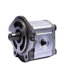
To retain our goodwill in clients"" consideration, we manufacture, trade and supply a quality approved Hydraulic Aluminium Gear Pumps. Our offered gear pumps are precisely manufactured using the latest technology and supreme quality components. Used in various industrial applications, these gear pumps are highly acknowledged by the clients. Our valuable clients can avail these gear pumps in different technical specifications and sizes.
With years of experience and knowledge in this domain, we are engaged in offering an excellent range of Hydraulic Gear Pump. The provided pump is manufactured using quality tested components and ultra-modern technology in sync with industry norms. Used in hydraulic fluid power applications, we offer this pump after testing it on different quality measures. Available in varied designs and sizes, this pump is offered at industry leading prices.
We are assisted by our truly skilled and seasoned professionals in manufacturing, trading and supplying a precision-engineered range ofMiddle Pressure Hydraulic Gear Pump. Offered gear pump is manufactured by proficient experts using optimum quality components and progressive technology. Our provided gear pump is designed to use for transporting high pressure and high volume flows. Apart from this, offered gear pump is examined on different parameters by experts.
Owing to our expertise in this domain, we are leading manufacturer of Hydraulic Pumps. The gear pumps offered by us are manufactured using finest material and contemporary technology. In order to conforming to international standards and regulations,
Our top priorities are reliability and easy installation when we design closed circuit pumps and motors for low power applications. U-style and inline options separate variable pumps and fixed motors, giving you great engineering flexibility. Features & benefits
Our Gear Type Flow Dividersdividers are manufactured utilizing optimum quality material and latest technology keeping in mind the set norms of industry. Offered flow dividers are quality checked on several quality parameters to ensure their defect free range. In addition, these flow dividers divides the Flow in equal proposition.
Gear Flow Divderdivides a flow in two usually equal parts. When flow passes through the flow divider in the opposite direction, the two part-flows are combined into one single flow (added).

www.powermotiontech.com is using a security service for protection against online attacks. An action has triggered the service and blocked your request.
Please try again in a few minutes. If the issue persist, please contact the site owner for further assistance. Reference ID IP Address Date and Time 8bf2006c85a66667641f5dd58dcb3d35 63.210.148.230 03/07/2023 05:21 AM UTC

Serving a multitude of industrial engineering sectors, as well as the global horticulture, shipbuilding, water treatment and automotive markets, Johnson Pump has always put customer needs first. Supplying an expansive portfolio of pumps (based on positive displacement and centrifugal mechanisms), plus all the necessary accessories. Through close interaction with the global customer base, Johnson Pump is able to provide focused solutions that exactly match specific application requirements. This is facilitated by our modular approach to design - which allows greater interchangeability between component parts, thereby simplifying logistical aspects (thanks to the ordering and storing of fewer part numbers) and allowing a wider array of different pump variants to be covered using a smaller inventory. The Johnson Pump portfolio covers internal gear pumps, impeller pumps and circulation pumps. All of these items deliver strong performance and continued reliability. The Johnson Pump engineering team designs low noise operating equipment, and engineered coatings to protect against debris damage.
Hydraulic pumps are mechanical devices that convert mechanical energy into hydraulic energy. They generate flow with enough power to overcome pressure induced by the load. Hydropack offer group 2 aluminum external gear pumps with different specifications.

Established in the year 1999, we, Advance Hydraulic Works are one of the renowned manufacturer of Hydraulic Motor And Hydraulic Valve and many more. We also provide Hydraulic Motor Repairing Service.

www.powermotiontech.com is using a security service for protection against online attacks. An action has triggered the service and blocked your request.
Please try again in a few minutes. If the issue persist, please contact the site owner for further assistance. Reference ID IP Address Date and Time 8bf2006c85a66667641f5dd58dcb3d35 63.210.148.230 03/07/2023 05:21 AM UTC

For hydraulic systems that place high demands on control engineering, servo pumps are the perfect solution. The basic version of these pump systems also consists of three main components:Servo inverter
Servo pumps control the pressure or the volume flow. They precisely convert electrical energy into the hydraulic energy that is currently needed in the system. The classic use of valves for control can be either completely or partially omitted. This considerably simplifies every hydraulic system.

Whenever you’re dealing with a hydraulic system you always get asked, “What is your systems pressure and flow rate?” or, “Why is pressure and flow so important?”
For our discussion, let’s talk specifically about fixed displacement components. There are variable displacement pumps and motors used in equipment today but to make these concepts easier to digest I will refer to fixed displacement components. Examples of fixed displacement components are gear pumps, gear motors, and hydraulic cylinders.Pressure and flow are the main variables when working with fluid power systems. Let’s look closer at flow rate.
Fixed displacement hydraulic motors require a fixed volume of oil to cause the shaft to turn 1 revolution. This volume is referred to the motors displacement, usually measured in cubic inch displacement (CID) or cubic centimeter (CC). If you supply the motor with 100 times its CID every minute, it will turn 100 RPM. Speed up the flow rate and motor will go faster, slow it down and the motor will turn slower.
Because of the differences in units of measure (gallons, inches, cubic inches, etc.) we have equations to help with the conversions. For example, a motor with a 3 CID displacement turning @ 1,000 RPM requires 3,000 cubic inches of oil flow every minute (3×1,000=3,000). To convert this to gallons we divide 3000 cubic inches by 231 (cubic inches per gallon). 3000/231=12.99 gallons per minute (round up to 13 GPM). Making the motor smaller will increase the speed, and making it larger will decrease the speed given the same flow rate.
There are some flow implications for tubes and hoses that need to be considered. Oil flowing through a tube or hose must move along the conductor. As the oil moves, it contacts the inside of the conductor causing friction. To overcome the friction, we need to generate pressure to cause the oil to move. If you look at a 100’ length of hose and measured the pressure at each end, the pressure at the downstream end will be lower than the upstream end. We refer to the difference as the back pressure.
What size hose should I use for the 13 GPM flow from the earlier motor example? There are many ways to evaluate hose diameter for a given flow rate. I prefer to use oil velocity. As you push the oil through a smaller and smaller hose the oil must flow faster and faster to maintain the flow rate. As you force the oil to move faster the back pressure increases because of the increased friction.
For this example, I would recommend 5/8 hose for the working lines and ¾ hose for the return lines. The suction line supplying the pump will need to be at least 1-1/4”. Suction lines are larger to prevent the pump from cavitating.
For the pressure line feeding the motor I would use a 5/8 hose. If 5/8 is not available ¾” or ½” would work. Know that ½ will have a higher pressure drop and cost more in fuel or electricity than the ¾ hose. ¾” hose cost more for the materials. How much available pressure you have can also play into the decision. If you are running up against the pressure rating for your pump the larger hose will help you save some pump pressure. Where ½ may have a slightly higher pressure drop using ¼” hose will have an extremely high pressure drop and could cause your system to fail.
When working with cylinders, speed refers to the rate the cylinder rod extends or retracts. This is typically referred to in inches per minute (IPM). The speed the rod will extend is related to the area of the piston the oil is pushing against. For a 3” bore cylinder the area is 7.07 cubic inches. We’ll discuss how to calculate that in a minute.
For this example, our pump flow is 1 GPM. We calculate the IPM by calculating the volume needed to displace the cap end of cylinder. To do this we need to know the Stroke of the cylinder, in this case 12”. The cubic Inches of oil needed to displace the cylinder is 7.07 cu/in * 12 inches of stroke (7.07 * 12) = 84.84 cubic inches. To keep things simple, I like to convert GPM to cubic inches per second. (1 GPM / 231) /60 = 3.85 cu inches per second.
Now if we divide 84.84 cubic inches /3.85 we will get the number of seconds to extend the cylinder 84.84/3.85= 22 seconds to extend 12 inches. Now we can get an inches per second rate. 12 / 22 = .545 inches per second. Converting inches per second to inches per minute you multiply by 60 (.545 * 60 = 32.7 inches per minute)
The larger the bore of the cylinder the slower it will extend, If the bore is made smaller, the cylinder will move faster given the same flow rate. There are many different types of cylinders:
The formulas are applied differently for different types of cylinders. Understanding the changes in area are critical to correctly predicting cylinder speeds.
Hydraulic pumps generate flow and tolerate pressure. The pressure comes from resistance to the oil flow. For example, a hydraulic cylinder that is not connected to anything will extend and retract a cylinder at low pressure. The pressure measured at the pump is what is required to overcome the seal friction of the cylinder and back pressure from the oil flowing through the hoses and valves.
Hydraulic components need to be protected from pressures above there designed capability. It is very important that a hydraulic system has a way of relieving the pressure should it go higher than the components are designed to tolerate. In a simple circuit the device that does this is typically a relief valve. It allows oil to flow back to tank if the maximum pressure setting is exceeded. This is done to protect the components. Without a relief valve the components in the system will attempt operate at the higher pressure, resulting in damage or failure of the component.
With hydraulic motors and pressure, we are looking at the torque the motor can handle. In the U.S., torque is typically measured in foot pounds (ft/lbs) or inch pounds (in/lbs). Torque is the unit of measure for defining the force on a shaft. Think about driving in a screw with a screwdriver. As the screw goes deeper into the material the force required to keep in moving increases. We define that force as torque. With a rotating motor shaft, the torque is transmitted into the motor through the shaft and makes the hydraulic pressure increase to keep the motor rotating. This is the resistance to flow that causes the pressure to increase. Given a fixed displacement the higher the torque at the shaft the higher the pressure needed to keep in moving. If the torque on the shaft is constant the hydraulic pressure needed will decrease if the motor displacement is increased, conversely if the motor is made smaller the pressure will increase. As we looked at earlier there is also change in RPM if the flow rate is constant.
For example, let’s use a 3” hydraulic cylinder. Using the formula to calculate area the cylinder has an area of 7.07 cubic inches. (3x3x.7854 = 7.07 cubic Inches area)
Let’s say we need to lift 15,000 lbs using this 3” cylinder, we can predict the system PSI with the formulas above. We know force (15,000 lbs) and area (7.07 cu/in) using some simple algebra we can rearrange the force formula to PSI = Force / Area (15,000 / 7.07 = 2,122 PSI)
Using a 3” cylinder I need 2,122 PSI to lift the load. The pump pressure will be higher because of seal friction and system back pressure. Probably closer to 2,250 PSI depending on hose size and valving selected.
We made the area smaller and the pressure to lift the load went up proportionally. The same thing is happening with the extending speed of the cylinder. At the same flow rate, the 2.5” cylinder extends faster than the 3” cylinder because it takes less oil to displace the 2.5” cylinder.
From the examples we looked at you can see that flow rate relates to the speed of your components. Increasing flow rate will make cylinders extend and retract faster and make motors run at higher RPM. Pressure is a reaction to the force required to move the load. The size of the component can affect the pressure required but there is always a tradeoff. Lower pressure typically means larger components resulting in slower speeds
When working with components in a hydraulic system always be aware of the pressure rating of the components. If the system will operate at 2500 PSI the relief will need to be set higher, 2650-2800 PSI. All components used on the pressure side of the circuit need to be rated for higher PSI than the relief valve setting. This includes the pump, directional control valves, hoses, adapters, cylinders, motors, pressure filters etc.
Items on the return side of the system can be rated for lower pressures because the PSI in that portion of the system stays relatively low. This is the return filter, cooler, tank, return hoses and adapters. Selecting components with the correct pressure rating will extend the life of your hydraulic system.
Features a hybrid drive system that combines the benefits of hydraulics with the controllability of an AC servo motor and inverter motor to satisfy a broad range of specifications with a small volume pump. Users will find energy savings in fields such as industrial machinery and machine tools.
Total weight 3.3kg. The weight of the device on ankle part where the exercise load is big is reduced to 0.97kg by wearing the power supply on the waist. 65Nm torque is generated by Takako"s standard 0.4cc pump.
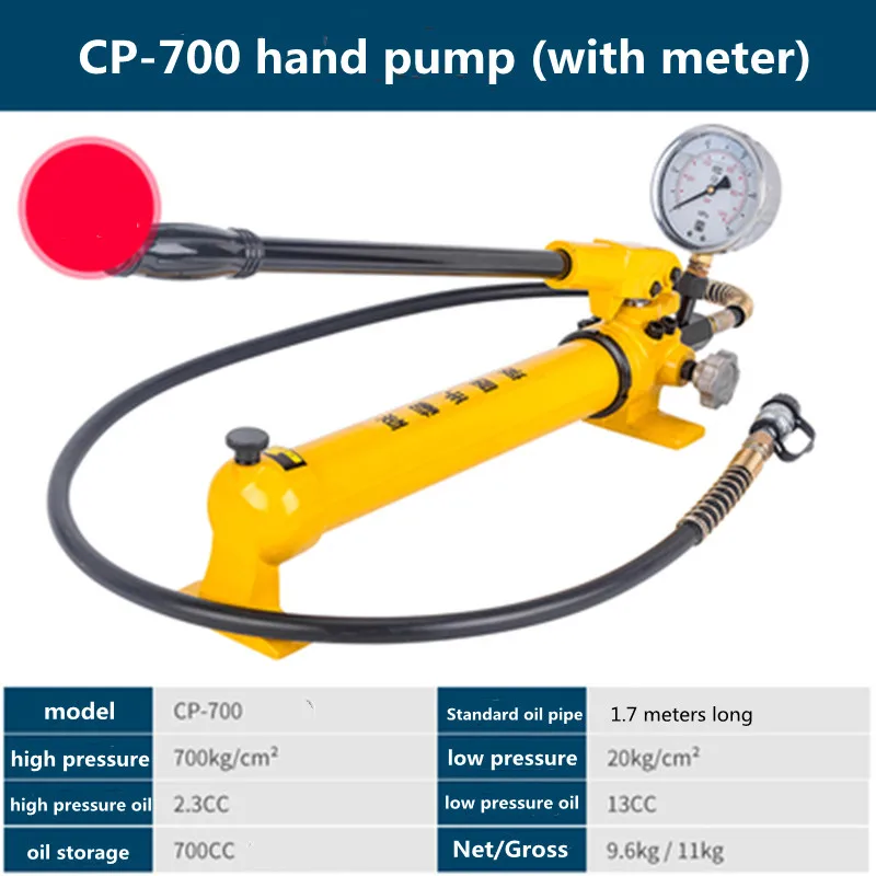
A continuous duty 4 hp (cv) gasoline pumps are best suited for medium size tools and cylinders. It"s a perfect choice for clamping, holding, positioning and lowering and lifting applications
High performance two-stage pump provides higher crossover pressure for faster cycle times and equipment operation; 50 cubic inches / minute @ 10,000 PSI (819,4 cm3 / min @ 700 bar).

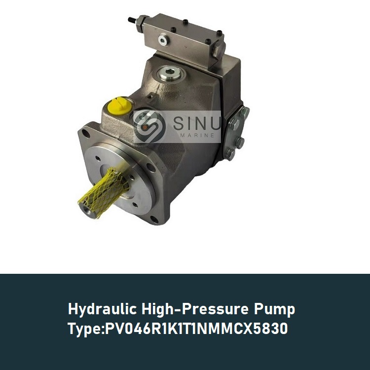
With fast control response and superior performance, the PVG is a variable-displacement axial-piston pump designed to take on your most demanding applications. It offers high-pressure, superior performance in a compact design — while thriving on low-viscosity fluids.
With fast control response and superior performance, the PVG is a variable-displacement axial-piston pump designed to take on your most demanding applications. It offers high-pressure, superior performance in a compact design — while thriving on low-viscosity fluids.
With fast control response and superior performance, the PVG is a variable-displacement axial-piston pump designed to take on your most demanding applications. It offers high-pressure, superior performance in a compact design — while thriving on low-viscosity fluids.
With fast control response and superior performance, the PVG is a variable-displacement axial-piston pump designed to take on your most demanding applications. It offers high-pressure, superior performance in a compact design — while thriving on low-viscosity fluids.
With fast control response and superior performance, the PVG is a variable-displacement axial-piston pump designed to take on your most demanding applications. It offers high-pressure, superior performance in a compact design — while thriving on low-viscosity fluids.
With fast control response and superior performance, the PVG is a variable-displacement axial-piston pump designed to take on your most demanding applications. It offers high-pressure, superior performance in a compact design — while thriving on low-viscosity fluids.
With fast control response and superior performance, the PVG is a variable-displacement axial-piston pump designed to take on your most demanding applications. It offers high-pressure, superior performance in a compact design — while thriving on low-viscosity fluids.
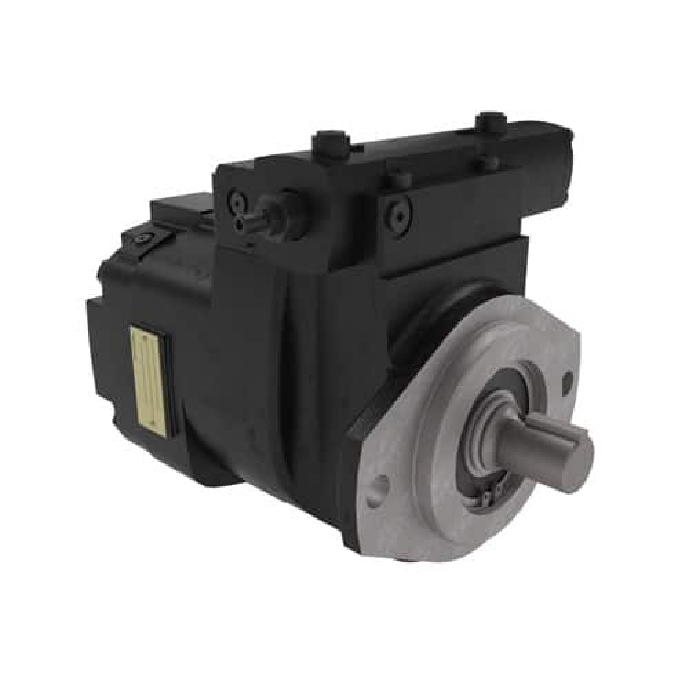
When you need peak performance from a variable-displacement axial-piston pump, the Oilgear pump PVV line is ready. No matter what pressure and flow demands you face, these pumps rise to the challenge.
When you need peak performance from a variable-displacement axial-piston pump, the Oilgear pump PVV line is ready. No matter what pressure and flow demands you face, these pumps rise to the challenge.
When you need peak performance from a variable-displacement axial-piston pump, the Oilgear pump PVV line is ready. No matter what pressure and flow demands you face, these pumps rise to the challenge.
When you need peak performance from a variable-displacement axial-piston pump, the Oilgear pump PVV line is ready. No matter what pressure and flow demands you face, these pumps rise to the challenge.
Quiet operation, high efficiency and compact design — all available at a competitive price. That’s what Oilgear PVWC closed-loop, hydrostatic axial-piston hydraulic pumps bring to the table. All designed around our proven rotating group.
Quiet operation, high efficiency and compact design — all available at a competitive price. That’s what Oilgear PVWC closed-loop, hydrostatic axial-piston hydraulic pumps bring to the table. All designed around our proven rotating group.
Quiet operation, high efficiency and compact design — all available at a competitive price. That’s what Oilgear PVWC closed-loop, hydrostatic axial-piston hydraulic pumps bring to the table. All designed around our proven rotating group.
Designed to be cost-effective, stable and low-maintenance, PVWJ is a variable-displacement axial-piston pump with a medium control response. Like all Oilgear pumps, it thrives on low-viscosity fluids — and comes in a variety of frame sizes and available displacement rates.
Designed to be cost-effective, stable and low-maintenance, PVWJ is a variable-displacement axial-piston pump with a medium control response. Like all Oilgear pumps, it thrives on low-viscosity fluids — and comes in a variety of frame sizes and available displacement rates.
Designed to be cost-effective, stable and low-maintenance, PVWJ is a variable-displacement axial-piston pump with a medium control response. Like all Oilgear pumps, it thrives on low-viscosity fluids — and comes in a variety of frame sizes and available displacement rates.
Designed to be cost-effective, stable and low-maintenance, PVWJ is a variable-displacement axial-piston pump with a medium control response. Like all Oilgear pumps, it thrives on low-viscosity fluids — and comes in a variety of frame sizes and available displacement rates.
Designed to be cost-effective, stable and low-maintenance, PVWJ is a variable-displacement axial-piston pump with a medium control response. Like all Oilgear pumps, it thrives on low-viscosity fluids — and comes in a variety of frame sizes and available displacement rates.
Designed to be cost-effective, stable and low-maintenance, PVWJ is a variable-displacement axial-piston pump with a medium control response. Like all Oilgear pumps, it thrives on low-viscosity fluids — and comes in a variety of frame sizes and available displacement rates.
Designed to be cost-effective, stable and low-maintenance, PVWJ is a variable-displacement axial-piston pump with a medium control response. Like all Oilgear pumps, it thrives on low-viscosity fluids—and comes in a variety of frame sizes and available displacement rates.
Designed to be cost-effective, stable and low-maintenance, PVWJ is a variable-displacement axial-piston pump with a medium control response. Like all Oilgear pumps, it thrives on low-viscosity fluids — and comes in a variety of frame sizes and available displacement rates.
Designed to be cost-effective, stable and low-maintenance, PVWJ is a variable-displacement axial-piston pump with a medium control response. Like all Oilgear pumps, it thrives on low-viscosity fluids — and comes in a variety of frame sizes and available displacement rates.
Designed to be cost-effective, stable and low-maintenance, PVWJ is a variable-displacement axial-piston pump with a medium control response. Like all Oilgear pumps, it thrives on low-viscosity fluids — and comes in a variety of frame sizes and available displacement rates.
Extremely effective across numerous industrial applications that require quick response in extreme environments, the XD5 series of pumps offer lightning-fast control response on both low-viscosity fluids and standard hydraulic oil. Engineered to handle the most challenging environments, they have been designed to be a high-performance solution for demanding mobile applications.

In a condition-based maintenance environment, the decision to change out a hydraulic pump or motor is usually based on remaining bearing life or deteriorating efficiency, whichever occurs first.
Despite recent advances in predictive maintenance technologies, the maintenance professional’s ability to determine the remaining bearing life of a pump or motor, with a high degree of accuracy, remains elusive.
Deteriorating efficiency on the other hand is easy to detect, because it typically shows itself through increased cycle times. In other words, the machine slows down. When this occurs, quantification of the efficiency loss isn’t always necessary. If the machine slows to the point where its cycle time is unacceptably slow, the pump or motor is replaced. End of story.
In certain situations, however, it can be helpful, even necessary, to quantify the pump or motor’s actual efficiency and compare it to the component’s native efficiency. For this, an understanding of hydraulic pump and motor efficiency ratings is essential.
There are three categories of efficiency used to describe hydraulic pumps (and motors): volumetric efficiency, mechanical/hydraulic efficiency and overall efficiency.
Volumetric efficiency is determined by dividing the actual flow delivered by a pump at a given pressure by its theoretical flow. Theoreticalflow is calculated by multiplying the pump’s displacement per revolution by its driven speed. So if the pump has a displacement of 100 cc/rev and is being driven at 1000 RPM, its theoretical flow is 100 liters/minute.
Actualflow has to be measured using a flow meter. If when tested, the above pump had an actual flow of 90 liters/minute at 207 bar (3000 PSI), we can say the pump has a volumetric efficiency of 90% at 207 bar (90 / 100 x 100 = 90%).
Its volumetric efficiency used most in the field to determine the condition of a hydraulic pump - based on its increase in internal leakage through wear or damage. But without reference to theoretical flow, the actual flow measured by the flow meter would be meaningless.
A pump’s mechanical/hydraulic efficiency is determined by dividing thetheoretical torque required to drive it by the actual torque required to drive it. A mechanical/hydraulic efficiency of 100 percent would mean if the pump was delivering flow at zero pressure, no force or torque would be required to drive it. Intuitively, we know this is not possible, due to mechanical and fluid friction.
Table 1. The typical overall efficiencies of hydraulic pumps, as shown above, are simply the product of volumetric and mechanical/hydraulic efficiency.Source: Bosch Rexroth
Like theoretical flow, theoretical drive torque can be calculated. For the above pump, in SI units: 100 cc/rev x 207 bar / 20 x p = 329 Newton meters. But like actual flow, actual drive torque must be measured and this requires the use of a dynamometer. Not something we can - or need - to do in the field. For the purposes of this example though, assume the actual drive torque was 360 Nm. Mechanical efficiency would be 91% (329 / 360 x 100 = 91%).
Overall efficiency is simply the product of volumetric and mechanical/hydraulic efficiency. Continuing with the above example, the overall efficiency of the pump is 0.9 x 0.91 x 100 = 82%. Typical overall efficiencies for different types of hydraulic pumps are shown in the Table 1.
System designers use the pump manufacturers’ volumetric efficiency value to calculate the actual flow a pump of a given displacement, operating at a particular pressure, will deliver.
As already mentioned, volumetric efficiency is used in the field to assess the condition of a pump, based on the increase in internal leakage due to wear or damage.
When calculating volumetric efficiency based on actual flow testing, it’s important to be aware that the various leakage paths within the pump are usually constant. This means if pump flow is tested at less than full displacement (or maximum RPM) this will skew the calculated efficiency - unless leakage is treated as a constant and a necessary adjustment made.
For example, consider a variable displacement pump with a maximum flow rate of 100 liters/minute. If it was flow tested at full displacement and the measured flow rate was 90 liters/minute, the calculated volumetric efficiency would be 90 percent (90/100 x 100). But if the same pump was flow tested at the same pressure and oil temperature but at half displacement (50 L/min), the leakage losses would still be 10 liters/minute, and so the calculated volumetric efficiency would be 80 percent (40/50 x 100).
The second calculation is not actually wrong, but it requires qualification: this pump is 80 percent efficient at half displacement. Because the leakage losses of 10 liters/minute are nearly constant, the same pump tested under the same conditions will be 90 percent efficient at 100 percent displacement (100 L/min) - and 0 percent efficient at 10 percent displacement (10 L/min).
To help understand why pump leakage at a given pressure and temperature is virtually constant, think of the various leakage paths as fixed orifices. The rate of flow through an orifice is dependant on the diameter (and shape) of the orifice, the pressure drop across it and fluid viscosity. This means that if these variables remain constant, the rate of internal leakage remains constant, independent of the pump"s displacement or shaft speed.
Overall efficiency is used to calculate the drive power required by a pump at a given flow and pressure. For example, using the overall efficiencies from the table above, let us calculate the required drive power for an external gear pump and a bent axis piston pump at a flow of 90 liters/minute at 207 bar:
As you’d expect, the more efficient pump requires less drive power for the same output flow and pressure. With a little more math, we can quickly calculate the heat load of each pump:
No surprise that a system with gear pumps and motors requires a bigger heat exchanger than an equivalent (all other things equal) system comprising piston pumps and motors.
Brendan Casey has more than 20 years experience in the maintenance, repair and overhaul of mobile and industrial equipment. For more information on reducing the operating cost and increasing the...


 8613371530291