
what size hydraulic pump do i need price

Gear pumps have very few moving parts. They consist of two intermeshing gears. These pumps have a constant flow rate. They operate at pressures generally between 50 and 210 bar. Gear pumps operate at the highest speeds of any pumps at up to 3000-6000 rpm.
In an external-gear pump, only one of the gear wheels, the drive gear, is connected to the drive. The other gear wheel, the driven gear, rotates in the opposite direction, so that the teeth of the rotating gear wheels interlock.
There are also double external-gear pumps, which combine two gear pumps driven by the same coupling shaft. A double external-gear pump has the advantage of supplying two independent hydraulic circuits, and also provides more flow to one circuit.

If you plan to replace the hydraulic pump in your log splitter or build your log splitter, you should know the size of the hydraulic pump that fits your log splitter. Log splitters are designed to split logs efficiently.
The machine uses a hydraulic system to power the splitting wedge to split logs efficiently. The hydraulic pump is an integral component of gas and electric splitters to provide the necessary power to do the job properly.
A log splitter is a powerful machine that splits logs of various sizes using hydraulic pressure. All log splitters – whether electric, gas, or manual – use hydraulics to feed the splitting wedge to cut the logs to just about any size you prefer.
The hydraulics system found in a log splitter consists of an engine, a hydraulic cylinder, a valve, an oil pump to create oil pressure, and a tank to hold and feed oil through the system.
Since the log splitter pump is one of the most important components of the machine, choosing the right kind of hydraulic pump for your log splitting machine becomes crucial when you need to replace the pump or plan to build your own log splitter.
Hydraulic pumps work according to the theory of hydraulics. The Principle of hydraulics or Pascal’s law governs how hydraulics work. Pascal’s law states that when you apply pressure to a specific point of a closed or confined fluid, the pressure will transmit to all other fluid points without any losses.
The hydraulic pump converts mechanical energy into hydraulic energy by using flowing water. The hydraulic pump uses flowing water to create a hydraulic system.
Even though the system is quite complicated, the operation is simple. Hydraulics provide force in a specific area. This force is what we call pressure which helps the log splitter perform its job effectively.
Log splitter pumps are two-stage hydraulic pumps. The entire splitting system is dependent on the pump. The pump consists of two pumping sections as well as an internal pressure sensing valve. One section of the pump helps generate the maximum flow rate at a lower pressure, and it is used to draw the piston back for the system to reset after splitting the log.
It takes very little force to draw the piston back into the cylinder after splitting the log. But, it should happen quickly. That is why you need the highest possible flow rate at low pressure.
When pushing the piston into the log, you need the highest possible pressure to generate maximum splitting force to split the logs efficiently. The flow rate is not a big issue here. Hence, the pump will switch to a high-pressure and low-volume stage to split the log.
When the size of the pump increases, it requires more fluid. But when there is more fluid in the cylinder of the pump, the speed & force of the pump decrease. That is why you need to choose the right size pump for your log splitter.
You can split logs more efficiently when opting for the correct size hydraulic pump for your log splitter. There are different sizes of hydraulic pumps in the market today. You should do your homework properly and opt for the right size pump for your log splitter.
The latest hydraulic pumps available in the market are based on GPM (Gallons per minute). The higher the GPM, the smaller the cylinder. The splitting force of the pump depends on the cylinder.
The pump that your log splitter needs will be dependent on the engine size of the machine. For example, a 5.5-6 hp engine can handle an 11 GPM 2-stage hydraulic pump, while an 8 hp or bigger engine can handle a 16 GPM 2-stage pump.
The engine of a log splitter works on hydraulics. While the pump will create the driving force, the hydraulic cylinder will work in unison with the valves, influencing splitting power and speed. If your log splitter has a 6-7 Horsepower engine, you should opt for a two-stage hydraulic pump (about 3000 PSI) with 11 GPM.
To get more speed, the pump either needs more flow (GPM) or a smaller cylinder. Smaller cylinders don’t require more power but will produce less force. More flow comes from a larger hydraulic pump. You will get the same force with a larger pump but supply more horsepower to the new hydraulic pump.
Are you planning to replace the hydraulic pump in your log splitter or build your own log splitter? If so, you should understand the basics of how a hydraulic pump works and what size pump to choose for your log splitter. To achieve automation, efficiency, and effectiveness, all log splitters rely on hydraulics.
Therefore, you should not worry too much as the size of the pump is only one aspect to look at. But the right decision about the size of the hydraulic pump is always useful in usage.

An electric motor can be overloaded for short periods during the cycle provided the average horsepower is no greater than its nameplate rating plus service factor where this applies.
The amount of intermittent overloading is up to the user, but we suggest the overload be no more than 25% above its nameplate current rating sustained no longer than about 10% of the time required for a complete cycle.
Most A-C 60 Hz motors can be operated on a 50 Hz line and vice versa, but adjustments will have to be made in the current, HP, and speed ratings. The important thing to remember is that it is the current which causes heating. The HP which can be produced will be related to its current draw, and may be more or less than its nameplate rating.
*Voltage adjustment is to maintain current at rated value, to produce rated shaft torque. Current is always a limiting factor on a variation in rated Hz (frequency) or voltage.
Nameplate HP is based on full voltage being available. HP output is a combination of voltage times current. If voltage is too low, then to produce rated HP the current must be too high, and this overheats the motor. Motors can usually accommodate as low as 90% of rated voltage and still produce nameplate HP although temperature rise in the windings will be greater than rated rise. For permanent operation on a voltage source known to be low, the HP load should be limited, and reduced by the same percentage that the voltage is low.
If motor load does not exceed nameplate HP rating, full load current will be lower than nameplate rating and the motor will run cooler than rating. However, its starting and breakdown current (at stall) will be higher than normal. The wiring, fusing, and thermal overload protection will have to be sized accordingly. Motor noise will increase.
Using a 20 HP motor on a system which requires only 10 HP, for example, will give good results for running the pump but will consume more electricity than a 10 HP motor and will cause the power factor of the plant electric system to be poorer, especially during periods the motor is idling. Idling current of a 20 HP motor is about half the full load current of a 10 HP motor. This is an extra power waste during periods in the cycle when the pump is idling.
Using a 20 HP motor on a system which requires 25 HP for brief periods is quite possible, but during overload periods the current of such a motor maybe-about twice the current of a 25 HP motor. There will be an extra waste of power during peak periods in the cycle. But the smaller motor could more than make this up during periods in the cycle when less than 20 HP is required.
Log splitters are designed with a simple process in mind: to split logs efficiently. To do so, almost all use a hydraulic system to pressurize the driving force of the splitting wedge. When you purchase a log splitter, you don’t have to worry much about the individual parts other than for basic maintenance needs and cleaning purposes.
But if you are interested in building your own log splitter, which is a very realistic option due to the simplicity of the machinery, then you do need to know what parts are best for effective splitting power. Gas and electric splitters utilize a hydraulic pump which is the integral component of hydraulic power. If you were wondering what size hydraulic pump for a log splitter you need, this article explains below its use and what to look for.
Log splitters are powerful machines that provide a splitting pressure to logs of various sizes. Almost all splitters use hydraulics whether it is pressurized via an electric, gas, or manual power source. These hydraulics feed a splitting wedge of your model of choice to make short work of just about any size log you you need to cut down to size.
One of the simplest hydraulic systems you can find in use is a log splitter. The basics of hydraulic pressure utilize an engine, oil pump to create oil pressure, a hydraulic cylinder that works with a valve for splitting power, and tank to hold and feed oil through the system.
If you are serious about making your own backyard log splitter, then you want to have, at a minimum, the following components to provide the right amount of force and power for basic splitting of averaged sized, seasoned logs:
But you may want a bit more force for heavier workloads, which is why I’ve explained below how a pump can help determine your splitter’s speed, and influence the cutting force. Read more about how a log splitter works, how to care for it, and what you need to build your own.
Mentioned multiple times above is the use of a two-stage pump that is most common for a hydraulic log splitter system. This is because it uses two different sets of gears doing the pumping to keep you machine running smoothly and providing the power you need at the speed you desire.
Although a two-stage pump is the best option for your log splitter, you can manipulate the amount of force it exerts through which size cylinder you choose. To calculate your own splitter’s force and speed based on the choices you make, you can use this handy calculator tool.
The entire splitting system is dependent upon the pump that consists of two pumping sections and an internal pressure sensing valve. One of these sections generates the maximum flow rate rated at at lower pressure that is used to draw the piston back for the system to reset after splitting. The other section provides the highest possible pressure to generate maximum splitting force.
Knowing the maximum pressure generated by a pump determines the splitting powerof the pump, and one thing you will notice is that most companies are fairly generous in their tonnage claims and round up more often than not. To figure the tonnage provided by the splitter, simply multiple the maximum pressure of the pump (a two-stage pump applies about 3,000 PSI), by the total surface area of the piston in square inches. The resulting number is the total available pressure.
You also can determine the cycle time of a piston to figure how quickly you can work through a pile of logs. To move a 4 inch piston 24 inches (the common piston length) you need 301 cubic inches of oil. Since a gallon of hydraulic fluid takes up 231 cubic inches, you need to pump, at a minimum, 1.5 gallons of fluid to push the piston in one direction.
The flow rate of the pump is dependent on the size of the engine powering the system. If your engine is capable of providing an 11 gallon per minute rate, then it will take approximately 20 to 30 seconds to cut, and around 10 seconds to reset. Common horsepower minimum requirements for a two-stage pump are:
For a dependable machine, you want to incorporate a two-stage pump to work with whatever size engine and cylinder you decide upon for cutting wood. These keep your splitter working smoothing and efficiently, and allow you to dictate speed and force to handle whatever size job you have in mind. If you have any further questions, or want to add to this information, please do so below. And, as always, please share.

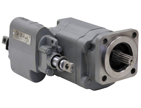
The goal of a hydraulic pump is to move hydraulic fluid through a hydraulic system, acting much like the beating heart of the system. There are two things that all hydraulic pumps have in common: (1) they provide hydraulic flow to other components (e.g., rams, hydraulic motors, cylinder) within a hydraulic system, and (2) they produce flow which in turn generates pressure when there is a resistance to flow. In addition, most hydraulic pumps are motor-driven and include a pressure relief valve as a type of overpressure protection. The three most common types of hydraulic pumps currently in use are gear, piston, and vane pumps.
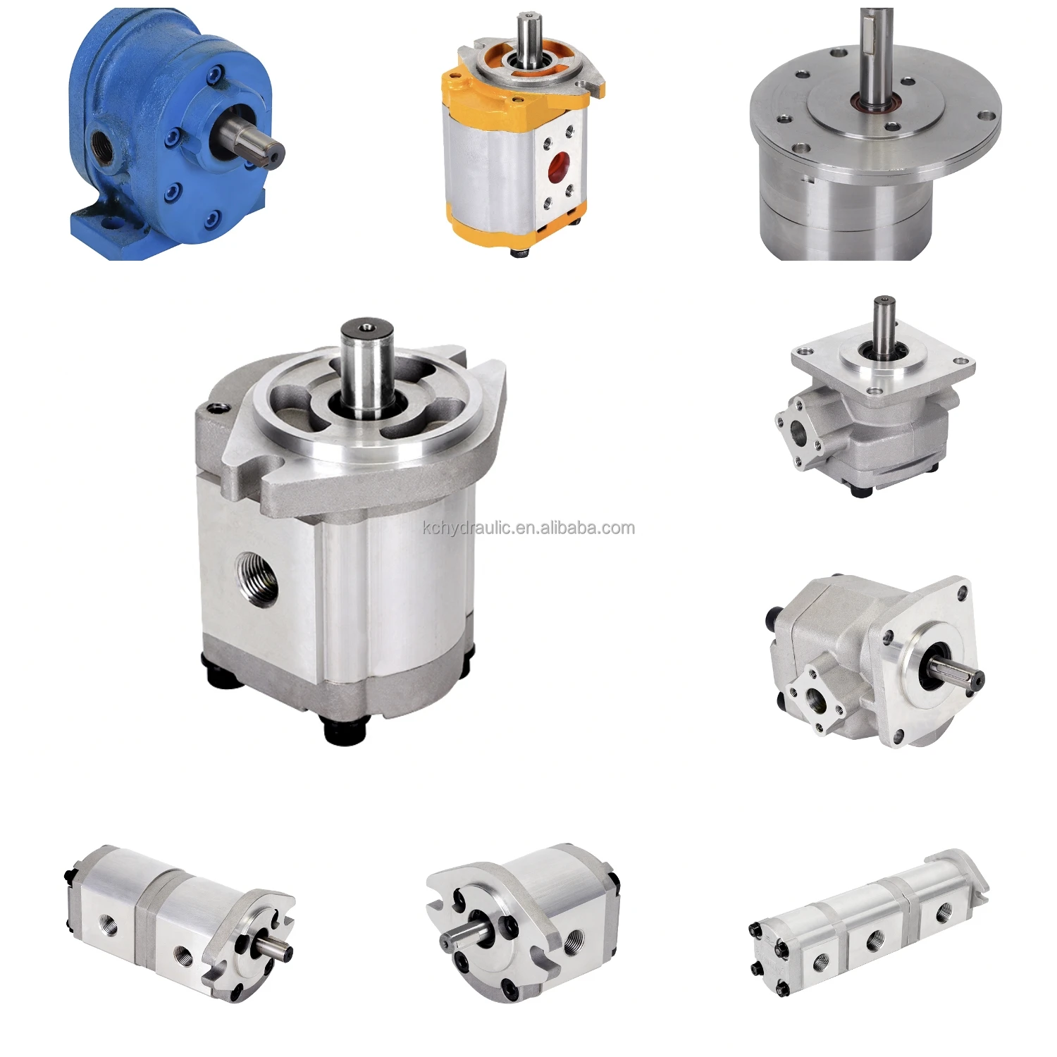
In a gear pump, hydraulic fluid is trapped between the body of the pump and the areas between the teeth of the pump’s two meshing gears. The driveshaft is used to power one gear while the other remains idle until it meshes with the driving gear. These pumps are what is known as fixed displacement or positive displacement because each rotation of the shaft displaces the same amount of hydraulic fluid at the same pressure. There are two basic types of gear pumps, external and internal, which will be discussed in a moment.
Gear pumps are compact, making them ideal for applications that involve limited space. They are also simple in design, making them easier to repair and maintain. Note that gear pumps usually exhibit the highest efficiency when running at their maximum speed. In general, external gear pumps can produce higher levels of pressure (up to 3,000 psi) and greater throughput than vane pumps.
External gear pumps are often found in close-coupled designs where the gear pump and the hydraulic motor share the same mounting and the same shaft. In an external gear pump, fluid flow occurs around the outside of a pair of meshed external spur gears. The hydraulic fluid moves between the housing of the pump and the gears to create the alternating suction and discharge needed for fluid flow.
External gear pumps can provide very high pressures (up to 3,000 psi), operate at high speeds (3,000 rpm), and run more quietly than internal gear pumps. When gear pumps are designed to handle even higher pressures and speeds, however, they will be very noisy and there may be special precautions that must be made.
External gear pumps are often used in powerlifting applications, as well as areas where electrical equipment would be either too bulky, inconvenient, or costly. External gear pumps can also be found on some agricultural and construction equipment to power their hydraulic systems.
In an internal gear pump, the meshing action of external and internal gears works with a crescent-shaped sector element to generate fluid flow. The outer gear has teeth pointing inwards and the inner gear has teeth pointing outward. As these gears rotate and come in and out of mesh, they create suction and discharge zones with the sector acting as a barrier between these zones. A gerotor is a special type of internal gear pump that eliminates the need for a sector element by using trochoidal gears to create suction and discharge zones.
Unlike external gear pumps, internal gear pumps are not meant for high-pressure applications; however, they do generate flow with very little pulsation present. They are not as widely used in hydraulics as external gear pumps; however, they are used with lube oils and fuel oils and work well for metering applications.
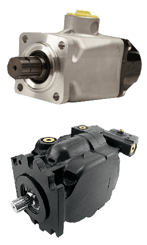
In a piston pump, reciprocating pistons are used to alternately generate suction and discharge. There are two different ways to categorize piston pumps: whether their piston is axially or radially mounted and whether their displacement is fixed or variable.
Piston pumps can handle higher pressures than gear or vane pumps even with comparable displacements, but they tend to be more expensive in terms of the initial cost. They are also more sensitive to contamination, but following strict hydraulic cleanliness guidelines and filtering any hydraulic fluid added to the system can address most contamination issues.
In an axial piston pump, sometimes called an inline axial pump, the pistons are aligned with the axis of the pump and arranged within a circular cylinder block. On one side of the cylinder block are the inlet and outlet ports, while an angled swashplate lies on the other side. As the cylinder block rotates, the pistons move in and out of the cylinder block, thus creating alternating suction and discharge of hydraulic fluid.
Axial piston pumps are ideal for high-pressure, high-volume applications and can often be found powering mission-critical hydraulic systems such as those of jet aircraft.
In a bent-axis piston pump (which many consider a subtype of the axial piston pump), the pump is made up of two sides that meet at an angle. On one side, the drive shaft turns the cylinder block that contains the pistons which match up to bores on the other side of the pump. As the cylinder block rotates, the distances between the pistons and the valving surface vary, thus achieving the necessary suction and discharge.
In a radial piston pump, the pistons lie perpendicular to the axis of the pump and are arranged radially like spokes on a wheel around an eccentrically placed cam. When the drive shaft rotates, the cam moves and pushes the spring-loaded pistons inward as it passes them. Each of these pistons has its own inlet and outlet ports that lead to a chamber. Within this chamber are valves that control the release and intake of hydraulic fluid.
In a fixed displacement pump, the amount of fluid discharged in each reciprocation is the same volume. However, in a variable displacement pump, a change to the angle of the adjustable swashplate can increase or reduce the volume of fluid discharged. This design allows you to vary system speed without having to change engine speed.
When the input shaft of a vane pump rotates, rigid vanes mounted on an eccentric rotor pick up hydraulic fluid and transport it to the outlet of the pump. The area between the vanes increases on the inlet side as hydraulic fluid is drawn inside the pump and decreases on the outlet side to expel the hydraulic fluid through the output port. Vane pumps can be either fixed or variable displacement, as discussed for piston pumps.
Vane pumps are used in utility vehicles (such as those with aerial ladders or buckets) but are not as common today, having been replaced by gear pumps. This does not mean, however, that they are not still in use. They are not designed to handle high pressures but they can generate a good vacuum and even run dry for short periods of time.
There are other key aspects to choosing the right hydraulic pump that goes beyond deciding what type is best adapted to your application. These pump characteristics include the following:
Selecting a pump can be very challenging, but a good place to start is looking at the type of pump that you need. Vane pumps have been largely replaced by compact, durable gear pumps, with external gear pumps working best for high pressure and operating speeds while internal gear pumps are able to generate flow with very little pulsation. However, vane pumps are still good for creating an effective vacuum and can run even when dry for short periods of time. Piston pumps in general are more powerful but, at the same time, more susceptible to contamination.
Whether the pump is needed for the rugged world of mining, the sterile world of food and beverage processing, or the mission-critical aerospace industry, MAC Hydraulics can assist you with selecting, installing, maintaining, and repairing the right pump to meet the needs of your hydraulic system. In the event of a breakdown, our highly skilled technicians can troubleshoot and repair your pump — no matter who the manufacturer happens to be. We also offer on-site services that include common repairs, preventative maintenance, lubrication, cleaning, pressure testing, and setting.

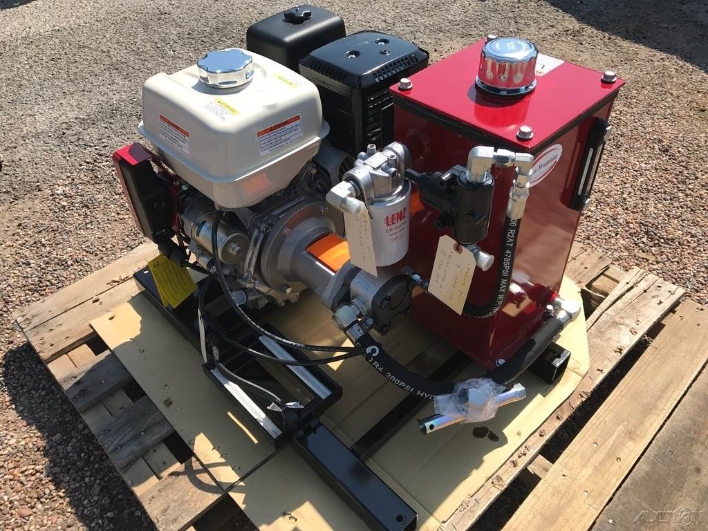
This 2-Stage pump fits a wide variety of log splitters and outdoor power equipment and works in both horizontal and vertical orientations. The included inlet nipple requires a 1" inner diameter suction hose.
Rated for up to 3,000 PSI at 3,600 RPM, this pump can power log splitters from 5 to 35 tons, depending on the inner diameter of the hydraulic cylinder. It features a fast cycle time by moving quickly when unloaded. It automatically shifts to low-flow/high-pressure mode at 500 PSI.
Be sure to use AW-32 10-Weight (ISO 32) or AW-46 20-Weight (ISO 46) light hydraulic fluid or Dexron III automatic transmission fluid. This pump is not designed for use with “universal” or "tractor" transmission oil, such as "303". The use of incorrect fluid may damage the pump and void the warranty.
Make sure the hydraulic fluid reservoir is not below the pump to ensure a sufficient flow of fluid to the pump. Suction-side filtration should be no finer than 150 microns. The use of a 10-25 micron filter on the suction side of the pump is too restrictive and will cause failure.
We recommend using an L-style jaw coupling to connect the pump to an engine. Couplings and mounting brackets are available. You should use at least a 5hp 163cc engine to maintain 3,600 RPM under load.

This 2-Stage pump fits a wide variety of log splitters and outdoor power equipment and works in both horizontal and vertical orientations. The inlet (suction) port is 1" NPT and the minimum suction hose inner diameter (ID) is 1-1/4". The inlet barbed fitting is not included but is available separately. Use a 1-1/4 ID Suction Hose and 3/4" ID high-pressure hose.
Rated for up to 3,000 PSI at 3,600 RPM, this pump can power log splitters from 5 to 37 tons, depending on the inner diameter of the hydraulic cylinder. It features a fast cycle time by moving quickly when unloaded.
Be sure to use AW-32 10-Weight (ISO 32) or AW-46 20-Weight (ISO 46) light hydraulic fluid. This pump is not designed for use with “universal” or "tractor" transmission oil, such as "303". The use of incorrect fluid may damage the pump and void the warranty.
Make sure the hydraulic fluid reservoir is not below the pump to ensure a sufficient flow of fluid to the pump. The hydraulic fluid reservoir should have a capacity of at least 12 gallons to allow sufficient cooling. Suction-side filtration should be no finer than 150 microns. The use of a 10-25 micron filter on the suction side of the pump is too restrictive and will cause failure.
We recommend using an L-style jaw coupling to connect the pump to an engine. Couplings and mounting brackets are available. You should use at least an 11.7hp 390cc engine to maintain 3,600 RPM under load.

For the people who have absolutely no idea about what these log splitters are, in simple terms, they can be called machines that chop wood using automation (or manual) power.
The primary purpose is to break these logs into pieces to aid their transport. The purpose of designing the log splitter is to simplify log splitting via automation (or manual) power.
Log splitters are phenomenal in their work, and the design aspect of log splitters is their main highlight. To achieve this automation, efficiency, and effectiveness, all these log splitters use hydraulics.
This two-stage hydraulic log splitter pump is the base of the hydraulic system. The hydraulic system is used to pressurize and create the force for splitting the wood.
This makes the log splitter pump the essential part of the log splitter. Whether you are well-versed with log splitters or have hardly heard about them, go through this article, and you will surely understand what size of log splitter pump you should use.
Log splitter pumps, as previously discussed, are a very crucial element. Thus, choosing the right kind of hydraulic log splitter pump becomes very important. The best way to go with this is by choosing the right size and quality materials for the log splitter pump. This will ensure high efficiency and effectiveness.
Before you make the decision, do analyze accordingly concerning your needs and log splitter. The size of log splitter pumps influences not only the performance but also the cost. Thus, the decision of choosing the size of hydraulic log splitter pumps depends upon three major factors:
Before deciding the size of log splitter pumps, it is essential to understand the hydraulics to determine the correct size based on the principle of log splitter pumps.
Hydraulic log splitter pumps work according to the phenomenon of hydraulics. Pascal’s law (Principle of hydraulics) governs hydraulics. It states that if you apply pressure to a particular point of a fluid (closed/confined), the pressure transmits to every other fluid point (with no losses).
Pumps convert one form of energy to another. As the name suggests, hydraulic pumps convert mechanical energy to hydraulic energy. For this conversion, hydraulic pumps use flowing water.
Using flowing water, these hydraulic pumps create a hydraulic system. This system is complicated, but in simpler terms, it provides force in a specific area, basically what we call pressure.
Two-stage hydraulic pumps are usually used as log splitter pumps. This complex system can be explained using an analogy. Consider the working of a vehicle, and it displaces itself irrespective of the heavyweight. It uses power for displacement.
This is precisely what happens in a log splitter, except that it happens at a smaller scale. Thus, the pump utilizes the conversion of the energy for running the log splitter.
Now that you know the log splitter and hydraulic pump details, we can discuss the size of the log splitter pump. Why should we be bothered about the size of the log splitter pump? The reason is that the size affects the speed and force (splitting).
Bigger the size of the log splitter pump (basically the pump cylinder’s size), the bigger the splitting force. This helps in the useful splitting of more extensive woods. But with the increase in the size of the hydraulic pump, it also requires more fluid. The requirement of more fluid decreases the speed.
This is the reason why the size of log splitter pumps becomes so essential. You can either choose the speed of splitting force. If you choose to increase one of the two-parameter, then the other one decreases.
To choose the best and correct size of your log splitter, you need to decide to improve either pump speed or splitting force. There are different size pumps available in the market according to your requirement.
Pumps available in the market are based on GPM (Gallons per minute). The higher the GPM, the smaller is the cylinder. The splitting force depends upon the cylinder. The higher the GPM, the smaller is the splitting force. To make it more transparent,
If you are interested in making a log splitter, which is possible as the calculations required for designing, parts required, and technique to make a log splitter is available. It can be employed if one shows interest in it. Only go for the DIY option if you are well-versed with machinery.
The engine of the log splitter works on the basics of hydraulics. The pump creates the driving force, and the hydraulic cylinder works in unison with the valves influencing splitting power and speed.
The engine used must be of 6-7 Horsepower. A two-stage hydraulic pump (about 3000 PSI) must be employed of 11 GPM. The standard hydraulic cylinder of 4-inch diameter and 24-inch length/height. Around 10-12-gallon capacity of the oil tank.
Note: If you want to play around with the values and choose the best according to your requirement, then use this calculator tool by international hydraulics.
Finally, it is your choice! As you know that you can either have a good speed or high splitting force, you must make your own decision with the size of log splitter pumps. You do not need to worry a lot as the size is only one aspect to look at, but the right decision about the size is always useful in usage.
The choice of DIY or buying one from the market is also your choice. If you are well-versed with calculations and machinery, then go for it as log splitters are expensive in the market.
If you know why you are employing a log splitter, it will help you make a better decision. For example, if you are one of those campers who requires a log splitter in his camps for firewood, go for the speedy ones (small cylinder size). The reason is that you would want to split wood faster instead of splitting larger pieces.
Irrespective of whether you buy a branded log splitter or DIY, they require regular maintenance and cleaning. For better results, go for the two-stage hydraulic pumps (even if they are a bit expensive).
If you follow the above tips, then the log splitter works effectively and efficiently. Taking the right decisions can help you enforce the right speed and optimum splitting force required for your log splitting.
Knowing how to right-size an electric motor for your hydraulic pump can help reduce energy consumption and increase operational efficiency. The key is to ensure the pump motor is operating at peak continuous load. But how can you know how much power is needed?
Before you can choose the correct electric motor, you must know how much horsepower (Hp) is required to drive the pump shaft. Generally, this is calculated by multiplying the flow capacity in gallons per minute (GPM) by the pressure in pounds per square inch (PSI). You then divide the resulting number by 1714 times the efficiency of the pump, for a formula that looks like this:
If you’re not sure how efficient your hydraulic pump is, it is advisable to use a common efficiency of about 85% (Multiplying 1714 x 0.85 = 1460 or 1500 if you round up). This work-around simplifies the formula to:
The above formula works in most applications with one notable exception: If the operating pressure of a pump is very low, the overall efficiency will be much lower than 85%. That’s because overall efficiency is equal to mechanical efficiency (internal mechanical friction) plus volumetric efficiency.
Internal friction is generally a fixed value, but volumetric efficiency changes depending on the pressure used. Low-pressure pumps have high volumetric efficiency because they are less susceptible to internal leakage. However, as the pressure goes up and internal fluids pass over work surfaces such as pistons, port plates, and lubrication points, the volumetric efficiency goes down and the amount of torque required to turn the pump for developing pressure goes up.
This variance makes it very important to know the efficiency of your pump if you’re using it at low pressure! Calculations that do not take low pressure into account will lead to a failed design.
If you calculate 20 GPM @ 300 PSI with an assumed overall efficiency of 89%, you would probably select a 5 Hp electric motor. However, if you calculate the same 20 GPM @ 300 PSI with the actual overall efficiency of 50%, you would know that you should be using a 7.5 Hp motor. In this example, making an assumption about the efficiency of your pump could result in installing a motor that is too large, driving up your overall operating cost.
There are many contributors to the overall efficiency of a hydraulic pump, and it pays to be as accurate as possible when choosing a motor. A best practice for proper sizing is to use published data from the pump vendor that shows actual input torque vs. pressure or overall efficiency vs pressure. Note that efficiency is also affected by RPM.
Identifying a right-sized motor for your hydraulic pump does not always ensure you are using the most efficient motor. Be sure to read Part 2 of this post to learn how RMS loading and Hp limiting can help you scale down the size of your electric motor to save money while maximizing efficiency.

www.powermotiontech.com is using a security service for protection against online attacks. An action has triggered the service and blocked your request.
Please try again in a few minutes. If the issue persist, please contact the site owner for further assistance. Reference ID IP Address Date and Time 8bf2006c85a66667641f5dd58dcb3d35 63.210.148.230 03/07/2023 04:57 AM UTC

Whether gear, vane, or piston pump, there may come a time when you have to replace your hydraulic pump. When your equipment isn’t working properly and you have narrowed the problem down to a hydraulic pump that needs to be replaced, what do you need to know?
The pump may simply be worn out—they do have a natural lifespan, as they are a wearable item in a hydraulic system. Although it is not possible to give an average lifespan given the different types of pumps and widely varying hours of operation; in general, you can expect many years of good operation from a hydraulic pump in most truck-mounted hydraulic systems. However, the life of a hydraulic pump might be much longer than what you are experiencing. Here are some questions you should ask:
Has the equipment been operating acceptably with this pump for a number of years without incident, and has the decline in performance been gradual over a longer period of time?
In this case, you’ll need to get the pump make and model number so that you can make sure that your replacement will be correct—either with an exact replacement or with another make that has the same operating specifications.
In any case, when replacing a failed hydraulic pump you will want to make sure to use this opportunity to also change out your hydraulic fluid (or at the very least use a filter cart and filter your oil). In the process of failing, your pump has introduced contaminants into your hydraulic system that you want to remove before they damage your new pump or any other hydraulic component. You will want to change your filter element(s) when you install your new pump, and then change it (them) out after a break-in period on your new pump.
If not, then let’s make sure there is not something else going on, or you may just find yourself replacing pumps frequently because the underlying problem hasn’t been addressed.
Input shaft is twisted/bcanroken: This occurs due to an extreme shock load to the pump. Typically, this happens when a relief valve is missing from the system, not functioning correctly, set to a much higher value than what the pump can withstand, or is too small for the system flow and thus cannot function correctly.
Shaft fretting:Fretting corrosion occurs under load in the presence of repeated relative surface motion, for example by vibration. Direct mount pump splines can be worn away. The solutions include:
Using larger pump and PTO shafts will not eliminate fretting, but may resolve the problem because of the increased metal available before the failure occurs.
Check to see that there is a sufficient amount of oil in the reservoir. Not just when the system is at rest, but also when all cylinders are extended to their maximum length or when all the components are running.
Make sure that the pump is able to get a good flow of oil from the reservoir—pumps are designed to have the oil feed pushed to the pump by gravity and atmospheric pressure, not by “sucking” oil. If the oil level in the reservoir is lower than the inlet of the pump, or the run too long or uphill, oil may not flow adequately to the pump. You can check if the pump is receiving oil adequately by using a vacuum gauge at the pump inlet. For a standard gear pump, at maximum operating RPM, the gauge should read a maximum of 5 inches HG. Larger numbers will damage a gear pump, and if you have a piston pump, the maximum number will be lower for good pump life.
Over pressurization: Pressure relief settings may have been adjusted or changed, and are now higher than what the pump can withstand without causing damage.
Pumps don’t produce pressure, they produce flow and are built to withstand pressure. When the system pressure exceeds the pump design, failure begins—either gradually or catastrophically.
When installing the new pump, back all the relief settings off. Then with the use of a pressure gauge T’d in at the pump outlet, gradually adjust the pressure relief setting until a cylinder or motor begins to move. Once the cylinder has reached the end of its stroke, gradually increase the pressure relief setting until reaching the max system pressure (which would be the pressure rating of the lowest rated component in the system). Sometimes, if a pump has been replaced and is larger than the original (produces more flow), the relief may not be able to allow all the flow being produced to escape back to tank. When that happens, the relief valve is “saturated” and the effect is the same as having no relief in the system. Pressures can reach levels much higher than the relief settings and components can be damaged or destroyed.
Contamination: Over time, the system oil has gotten dirty or contaminated and no longer is able to lubricate the pump, or is carrying contamination to the pump.
Make sure the oil is clean, the oil filer changed on schedule, and that there are no entry points for contamination like water, dust, or dirt from a reservoir filler cap that is unfiltered or missing, seals in motors or cylinders that are allowing contaminants in, etc.
New hoses can contain leftover bits of rubber and metal particles from the cutting and crimping process and should be cleaned out before installation.
Even new oil may be quite dirty if stored incorrectly, or exposed to dust and dirt. It’s always a good idea to use a filter cart and filter the system once it’s refilled with oil before turning on the system.

The ideal in hydraulic system designis to match overall efficiencies to the application performance expectation. This requires the designer to first match the motor, then the pump to a specific system performance expectation. Whether the requirement is to do something within a specific time frame, or in handling a given amount of load, the design of the entire system will change depending on the motor selected.
A hydraulic motor is a hydraulic actuator that, when properly connected into a hydraulic system, will produce a rotary actuation. This can be unidirectional or bidirectional depending on the system design. Motors are similar in design to pumps only where a pump takes a rotary actuation to move hydraulic fluid out of the unit, whereas a motor will take flow into itself and put out a rotaryactuation.
The motor selection comes first in the process because application design best practices require that you start with the load requirement, then work back to the prime mover—the pump that will put the fluid power into the motor selected to deliver the performance goal.
Each motor type—gear, vane, in-line piston, bent-axis piston and radial piston—has a specific performance profile. So, knowing the application performance requirement and which motor type best meets the objective is the first step. Then it’s necessary to evaluate the cost of your motor options along with the degree of complexity you want for the overall system.
In the end, it all goes back to the application’s performance expectations. Some have severe duty cycles, while others do not. If, for example, you consider running a low-efficiency, lighter-duty motor into a higher-duty cycle application, the life of the motor will be less than the life of a higher-duty cycle motor that is designed to operate in those types of environments. It is important to understand what operating pressures and flows are required for the motor selected to achieve the application performance expectations.
Each motor type has its own set of applications where they are a better choice than others. For example, if a small gear motor designed to operate at a max of 3,000 psi and 1,000 rpm is put into an application that requires it to run consistently at 3,000 psi and 1,000 rpm, the motor will be running in a “corner” overstressed condition and have a reduced life—even though it is technically within its ratings. The better motor choice would be a motor with higher ratings that will live longer in the application. Granted, there is a greater cost in going with a higher rated motor. The final decision always will depend on what is required in terms of application performance and motor life versus where you want to be with cost.
How motors are ratedMotors are rated bydisplacement, with displacement defined as the volume of fluid that it takes to rotate the shaft of the motor once. The common rating units are cubic inches per revolution (CIR), or cubic centimeters per revolution (CCR).
Motors are also rated bytorque—the amount of twisting force the motor can deliver. The common measurements of torque are inch-pounds (in.-lb) and Newton-meters (Nm). The torque of a motor is a function of motor displacement and system pressure.
Starting torqueis the torque the motor can generate to turn a load when starting from a stop. In general, starting toque is the lowest torque rating of a hydraulic motor due to inefficiencies.
The rotationalspeedof the motor shaft is measured in units of rotations per minute (rpm). Motor speed is a function of hydraulic input flow and motor displacement.
Pressure is generated by resistance to hydraulic flow. The more resistance, the higher the pressure. Common measurement units are pounds per square inch (psi), kilo Pascal’s (kPa) or bar.
Common motor classes and typesGenerally, hydraulic motors are placed into one of two classifications: high speed, low torque (HSLT) or low speed, high torque (LSHT).
Gear motorscome in two varieties—the gerotor/geroller or orbital and external spur gear designs. Orbital styles are classified as LSHT motors; however, some do exist with the HSLT classification. They consist of a matched gear set enclosed in a housing. When hydraulic fluid is moved into the motor, it causes the gears to rotate. One of the gears is connected to the motor output shaft, which produces the motor’s rotary motion. Key features include:
Applications include mobile hydraulics, agricultural machinery to drive conveyor belts, dispersion plates, screw conveyors or fans. Their biggest drawback is that they have a higher noise level.
Vane motorsare typically classified as HSLT units. However, larger displacements will fall into the LSHT range. Hydraulic fluid enters the motor and is applied to a rectangular vane, which slides into and out of the center rotor. This center rotor is connected to the main output shaft. The fluid being applied to the vane causes the output shaft to rotate.
Parker’s vane motors feature a balanced design where the inlet and outlet ports of the motor are applied to sections of the vane cartridge that are 180° apart from each other to ensure that the hydraulic forces are always in balance inside the motor. Key features include:
In-line piston motorsare classified as HSLT. Hydraulic fluid enters the motor and is applied to a series of pistons inside a cylinder barrel. The pistons are pressed against a swash plate, which is at an angle. The pistons push against this angle, which causes the rotation of the swash plate that is mechanically connected to the output shaft of the motor. The swash plate can be a fixed or variable angle. Variable angle motors can have their displacements adjusted between a maximum and minimum setting. The command signals to change the displacement can be electrical, hydraulic or a combination of both.
Bent-axis piston motorsare classified as HSLT. They are similar to inline motors except that the piston barrel is at an angle in relation to the swash plate. Hydraulic fluid enters the motor and is applied to the pistons, which are contained in a cylinder barrel. The pistons are at an angle to the drive shaft, which means that the piston will rotate the shaft as fluid enters the motor.
They can be both fixed and variable displacement. In a variable-displacement bent-axis motor, the cylinder barrel is rotated between maximum and minimum displacements. The command signals to change the displacement can be electrical, hydraulic or a combination of both.
They are best known for high performance, high pressures, high speeds and volumetric mechanical efficiencies in the 97 to 98% range. The also offer quick reaction and precise control. These motors are suitable for applications that require a significant amount of power. They are used to drive mobile and construction equipment, winches, ship-cranes and all kinds of heavy-duty hydraulic equipment for offshore and onshore operations.
Radial piston motorsare LSHT classified. These motors are designed with pistons arranged perpendicular to the output shaft. Typically, the pistons will ride against a cam, which is mechanically connected to the output shaft. The pistons will force the cam to rotate as hydraulic fluid enters the motor.
In general, these motors are fixed displacement. However, some versions will allow for variable displacement. They accomplish this by limiting the number of pistons that can receive hydraulic fluid. Other versions change the internal geometry of the cam the pistons areacting against.
Proper hydraulic motor selection starts with the expected performance required by the application, then works back to the prime mover—the pump. Then it is necessary to evaluate the cost of your motor options along with the degree of complexity you want for the overall system.

Replacing a failing hydraulic pump can be challenging. If the wrong alteration is made, you risk damaging your entire hydraulics system. Furthermore, there are many reasons why your pump may be failing, but not all of them may require a full replacement.
If your hydraulic pump isn’t working like it used to, you need to start troubleshooting as quickly as possible. Waiting until total failure will only result in costly downtime for your plant.
Some of the most common causes of hydraulic pump failure include fluid contamination, excess pressure, poor fluid quality, cavitation, excessive temperatures, and uncorrected leaks.
Contaminated fluid is the most common cause of hydraulic pump failure. It can take place when particulates get into the system through a cylinder rod or breather valve. Sometimes deficient repairs are the culprit. Contaminants can change the fluid properties, create buildup, and corrode parts, all circumstances that reduce the system’s efficiency.
Every pump is built to work within a specific safe pressure range. Pressures greater than this overwork the pump. The pump is likely to become damaged and eventually stop working entirely. In extreme cases, excess pressure can cause an explosion.
It’s critical to use high-quality cooling and lubrication oil with the correct mineral content and viscosity. Purity of fluid content is especially important for higher-pressure systems. Fluid that’s too viscous can lead to cavitation, which is a serious risk for pump damage. If the viscosity is too low, heat and friction levels can become dangerously high.
If vapor cavities arise, they can implode under pressure, which can erode the metal and contaminate the fluid. To prevent this, it’s important to properly maintain intake lines, keep fittings and clamps tight, maintain the correct fluid level, and check for leaky pump shaft seals.
Temperatures above180 degrees Fahrenheit can cause seal damage and fluid degradation. Depending on the fluid viscosity, that maximum temperature could be even lower. Overheating can be caused by low reservoir fluid levels, reservoir airflow obstructions, heat exchanger core blockage, internal leaks, and cavitation.
Leaks can arise from inadequate seals or internal component damage. If these aren’t taken care of, contaminants may enter the system and compromise the pump’s performance.
When inspecting your pump, looking out for these common signs:Increased Noise:All mechanical actuators make noise during operation, but hydraulic systems should not produce loud banging or knocking sounds. If you notice a new, unusual sound coming from your device, it may be experiencing cavitation or aeration.
High Temperatures: Hydraulic systems should never exceed 82 degrees Celsius/180 degrees Fahrenheit. If you detect a higher-than-average temperature, there may be a buildup of residue in the system. You need to address the problem quickly, as temperature changes can damage a pump quickly.
Put new oil in the tank. Be sure to fill the tank with the required oil grade, as pumps can fail if the wrong oil is administered throughout the system. Pumps require a consistent supply of oil and can fail if the levels drop too low.
Connect all lines to the cylinders and liquid motors. The rod end should be left disconnected. Turn on the circuits until the cylinder bottoms out. This process will flush contaminated oil from the cylinder. Repeat this process as many times as necessary. Reconnect lines to the rod end of the cylinder and add more oil as necessary.
Exact life expectancy depends on the specific pump and how frequently it’s used, but pumps often last for quite a few years. The manufacturer of your pump should specify how many hours or cycles a pump can be expected to provide before replacement is recommended.
Another critical factor in pump longevity is preventative maintenance. This includes daily maintenance tasks as well as those that need to be done annually.
In addition, perform any maintenance tasks the manufacturer recommends for your specific pump. And, always keep a record of completed maintenance tasks.
The exact cost depends on the type of pump, the pump manufacturer, and whether the replacement is done by a professional.Often a professional hydraulic pump replacement, including labor and parts, is in the vicinity of $1,500.The price depends on whether you buy directly from the manufacturer or from a third party.
Sometimes direct OEM replacement parts are expensive, and it can take weeks or months at times to receive the part. If you’re experiencing an emergency, or your pump has been discontinued by the manufacturer, purchasing a remanufactured pump may be the best solution for you, as they’re often less expensive than direct OEM replacements and the waiting times are typically shorter.
If you are purchasing a remanufactured pump, be sure to double check that your remanufacturer has an OEM guarantee, as you want to make sure the specifications of the remanufactured pump are the same as the OEM pump you are replacing.
Founded over 25 years ago, we’ve become the leading U.S. manufacturer of aftermarket hydraulic parts. We specialize in remanufacturing and repairing all types of pumps and components from manufacturers like Vickers/Eaton and Rexroth®. All of our pumps are made in-house in the U.S., guaranteed to meet OEM specifications, and are backed by a 12-month warranty.
Whenever you’re dealing with a hydraulic system you always get asked, “What is your systems pressure and flow rate?” or, “Why is pressure and flow so important?”
For our discussion, let’s talk specifically about fixed displacement components. There are variable displacement pumps and motors used in equipment today but to make these concepts easier to digest I will refer to fixed displacement components. Examples of fixed displacement components are gear pumps, gear motors, and hydraulic cylinders.Pressure and flow are the main variables when working with fluid power systems. Let’s look closer at flow rate.
Fixed displacement hydraulic motors require a fixed volume of oil to cause the shaft to turn 1 revolution. This volume is referred to the motors displacement, usually measured in cubic inch displacement (CID) or cubic centimeter (CC). If you supply the motor with 100 times its CID every minute, it will turn 100 RPM. Speed up the flow rate and motor will go faster, slow it down and the motor will turn slower.
Because of the differences in units of measure (gallons, inches, cubic inches, etc.) we have equations to help with the conversions. For example, a motor with a 3 CID displacement turning @ 1,000 RPM requires 3,000 cubic inches of oil flow every minute (3×1,000=3,000). To convert this to gallons we divide 3000 cubic inches by 231 (cubic inches per gallon). 3000/231=12.99 gallons per minute (round up to 13 GPM). Making the motor smaller will increase the speed, and making it larger will decrease the speed given the same flow rate.
There are some flow implications for tubes and hoses that need to be considered. Oil flowing through a tube or hose must move along the conductor. As the oil moves, it contacts the inside of the conductor causing friction. To overcome the friction, we need to generate pressure to cause the oil to move. If you look at a 100’ length of hose and measured the pressure at each end, the pressure at the downstream end will be lower than the upstream end. We refer to the difference as the back pressure.
What size hose should I use for the 13 GPM flow from the earlier motor example? There are many ways to evaluate hose diameter for a given flow rate. I prefer to use oil velocity. As you push the oil through a smaller and smaller hose the oil must flow faster and faster to maintain the flow rate. As you force the oil to move faster the back pressure increases because of the increased friction.
For this example, I would recommend 5/8 hose for the working lines and ¾ hose for the return lines. The suction line supplying the pump will need to be at least 1-1/4”. Suction lines are larger to prevent the pump from cavitating.
For the pressure line feeding the motor I would use a 5/8 hose. If 5/8 is not available ¾” or ½” would work. Know that ½ will have a higher pressure drop and cost more in fuel or electricity than the ¾ hose. ¾” hose cost more for the materials. How much available pressure you have can also play into the decision. If you are running up against the pressure rating for your pump the larger hose will help you save some pump pressure. Where ½ may have a slightly higher pressure drop using ¼” hose will have an extremely high pressure drop and could cause your system to fail.
When working with cylinders, speed refers to the rate the cylinder rod extends or retracts. This is typically referred to in inches per minute (IPM). The speed the rod will extend is related to the area of the piston the oil is pushing against. For a 3” bore cylinder the area is 7.07 cubic inches. We’ll discuss how to calculate that in a minute.
For this example, our pump flow is 1 GPM. We calculate the IPM by calculating the volume needed to displace the cap end of cylinder. To do this we need to know the Stroke of the cylinder, in this case 12”. The cubic Inches of oil needed to displace the cylinder is 7.07 cu/in * 12 inches of stroke (7.07 * 12) = 84.84 cubic inches. To keep things simple, I like to convert GPM to cubic inches per second. (1 GPM / 231) /60 = 3.85 cu inches per second.
Now if we divide 84.84 cubic inches /3.85 we will get the number of seconds to extend the cylinder 84.84/3.85= 22 seconds to extend 12 inches. Now we can get an inches per second rate. 12 / 22 = .545 inches per second. Converting inches per second to inches per minute you multiply by 60 (.545 * 60 = 32.7 inches per minute)
The larger the bore of the cylinder the slower it will extend, If the bore is made smaller, the cylinder will move faster given the same flow rate. There are many different types of cylinders:
The formulas are applied differently for different types of cylinders. Understanding the changes in area are critical to correctly predicting cylinder speeds.
Hydraulic pumps generate flow and tolerate pressure. The pressure comes from resistance to the oil flow. For example, a hydraulic cylinder that is not connected to anything will extend and retract a cylinder at low pressure. The pressure measured at the pump is what is required to overcome the seal friction of the cylinder and back pressure from the oil flowing through the hoses and valves.
Hydraulic components need to be protected from pressures above there designed capability. It is very important that a hydraulic system has a way of relieving the pressure should it go higher than the components are designed to tolerate. In a simple circuit the device that does this is typically a relief valve. It allows oil to flow back to tank if the maximum pressure setting is exceeded. This is done to protect the components. Without a relief valve the components in the system will attempt operate at the higher pressure, resulting in damage or failure of the component.
With hydraulic motors and pressure, we are looking at the torque the motor can handle. In the U.S., torque is typically measured in foot pounds (ft/lbs) or inch pounds (in/lbs). Torque is the unit of measure for defining the force on a shaft. Think about driving in a screw with a screwdriver. As the screw goes deeper into the material the force required to keep in moving increases. We define that force as torque. With a rotating motor shaft, the torque is transmitted into the motor through the shaft and makes the hydraulic pressure increase to keep the motor rotating. This is the resistance to flow that causes the pressure to increase. Given a fixed displacement the higher the torque at the shaft the higher the pressure needed to keep in moving. If the torque on the shaft is constant the hydraulic pressure needed will decrease if the motor displacement is increased, conversely if the motor is made smaller the pressure will increase. As we looked at earlier there is also change in RPM if the flow rate is constant.
For example, let’s use a 3” hydraulic cylinder. Using the formula to calculate area the cylinder has an area of 7.07 cubic inches. (3x3x.7854 = 7.07 cubic Inches area)
Let’s say we need to lift 15,000 lbs using this 3” cylinder, we can predict the system PSI with the formulas above. We know force (15,000 lbs) and area (7.07 cu/in) using some simple algebra we can rearrange the force formula to PSI = Force / Area (15,000 / 7.07 = 2,122 PSI)
Using a 3” cylinder I need 2,122 PSI to lift the load. The pump pressure will be higher because of seal friction and system back pressure. Probably closer to 2,250 PSI depending on hose size and valving selected.
We made the area smaller and the pressure to lift the load went up proportionally. The same thing is happening with the extending speed of the cylinder. At the same flow rate, the 2.5” cylinder extends faster than the 3” cylinder because it takes less oil to displace the 2.5” cylinder.
From the examples we looked at you can see that flow rate relates to the speed of your components. Increasing flow rate will make cylinders extend and retract faster and make motors run at higher RPM. Pressure is a reaction to the force required to move the load. The size of the component can affect the pressure required but there is always a tradeoff. Lower pressure typically means larger components resulting in slower speeds
When working with components in a hydraulic system always be aware of the pressure rating of the components. If the system will operate at 2500 PSI the relief will need to be set higher, 2650-2800 PSI. All components used on the pressure side of the circuit need to be rated for higher PSI than the relief valve setting. This includes the pump, directional control valves, hoses, adapters, cylinders, motors, pressure filters etc.
Items on the return side of the system can be rated for lower pressures because the PSI in that portion of the system stays relatively low. This is the return filter, cooler, tank, return hoses and adapters. Selecting components with the correct pressure rating will extend the life of your hydraulic system.
Are you trying to get a hydraulic pump for your dump trailer but you’re not sure where to start? Then, start by reading this post. In this article, we’ll review the six best hydraulic pumps for dump trailers in 2021, taking into account their durability, ease of use, tank size, power source, level of force, flow rate, functionality, and overall benefits.
We also provided a buyer’s guide that highlights the important factors to keep in mind while buying your hydraulic pump. We included a summary and FAQs that provide suitable answers to some of the burning questions related to hydraulic pumps. So, if you’re buying your first, second, or even your tenth hydraulic pump and you want to make a perfect choice, then look no further than this review.
However, hydraulic pumps for dump trailers are designed specifically for the dump trailer’s hydraulic system. They provide powerlifting capabilities to dump trailers required to lift the trailer bed from its frame to allow rapid unloading of heavy materials. They’re mounted either vertically or horizontally to the dump trailer’s hydraulic system to make lifting-up and lowering-down of the trailer’s bed as fast as possible.
Hydraulic pumps can generate strong power capable to drive almost any type of hydraulic cylinder or motor. Some hydraulic pumps for dump trailers are also suitable for systematic lifting of snowplow equipment, agricultural equipment, heavy equipment, and the like.
It’s tough to pick one product when you have man


 8613371530291