
wheel lift hydraulic pump free sample

When a hydraulic system fails, finding the source of the problem can be a challenge. Though hydraulic systems primarily consist of a sump, motor, pump, valves, actuators and hydraulic fluid, any of these parts could be the source of failure. That"s not to mention the additional potential for failure through human error and faulty maintenance practices. If your system fails, you need to know why it fails, how to find the failure and how to keep it running smoothly in the future, all while keeping personnel safe.
It"s often easy to tell when a hydraulic system fails — symptoms can include high temperatures, low pressure readings and slow or erratic operation are glaring problems. But what are the most common causes of hydraulic systems failures? We can trace most hydraulic issues back to a few common causes, listed below.
Air and water contamination are the leading causes of hydraulic failure, accounting for 80 to 90% of hydraulic failures. Faulty pumps, system breaches or temperature issues often cause both types of contamination.
Air contamination is the entrance of air into a hydraulic system and consists of two types — aeration and cavitation. Both can cause severe damage to the hydraulic system over time by wearing down the pump and surrounding components, contaminating hydraulic fluids and even overheating the system. Although we are not pump manufacturers, we know it is essential to be aware of these types of contamination and how to identify their symptoms.
Cavitation:Hydraulic oil consists of about 9% dissolved air, which the pump can pull out and implode, causing pump problems and damage to the pump and to other components in a hydraulic system over time. You can identify this problem if your hydraulic pump is making a whining noise.
Aeration:Aeration occurs when air enters the pump cavity from an outside source. Usually, loose connections or leaks in the system cause this issue. Aeration also creates a sound when the pump is running, which sounds like knocking.
Water contamination is also a common problem in hydraulic systems, often caused by system leaks or condensation due to temperature changes. Water can degrade hydraulic components over time through oxidation and freeze damage. A milky appearance in hydraulic fluid can help you identify water contamination.
Fluid oxidization: Extreme heat can cause hydraulic fluid to oxidize and thicken. This fluid thickening can cause buildups in the system that restrict flow, but can also further reduce the ability of the system to dissipate heat.
Fluid thickening:Low temperatures increase the viscosity of hydraulic oil, making it harder for the oil to reach the pump. Putting systems under load before the oil reaches 70 degrees or more can damage the system through cavitation.
Fluid levels and quality can affect hydraulic system performance. Low fluid levels and inappropriate filtration can result in air contamination, while fluid contamination can cause temperature problems. Leaks can further exacerbate both issues.
Using the correct type of fluid is also essential, as certain hydraulic oils are compatible with specific applications. There are even oil options that offer higher resistance to temperature-related problems. Some oils even offer anti-wear and anti-foam additives to help prevent against wear and air contamination, respectively.
Human error is the base cause of many hydraulic system problems. Some of the most common errors that may result in your hydraulic pump not building pressure include the following.
Faulty installations: Improper installation of any component in a hydraulic system can result in severe errors. For example, the pump shaft may be rotating in the wrong direction, negatively affecting pressure buildup, or pipes may be incorrectly fitted, resulting in leaks.
Incompatible parts: An inexperienced installer may put mismatched components together, resulting in functional failures. For example, a pump may have a motor that runs beyond its maximum drive speed.
Improper maintenance or usage:Using systems outside their operational capabilities or failing to perform regular maintenance are some of the most common causes of hydraulic system damage, but are easy to rectify through updated maintenance policies and training.
The sources of system failures can be tricky to identify, but some hydraulic troubleshooting steps can help narrow down the options. So how do you troubleshoot a hydraulic system? Here are some of the fundamentals.
Check the pump: Take the pump assembly apart and assess all parts to ensure that they are functional and installed correctly. The most common problem areas include the pump shaft, coupling and filter.
Check the fluids:Check the level, color and viscosity of the hydraulic oil to ensure it meets specifications and has not become contaminated. Low hydraulic fluid symptoms include pressure or power loss. When in doubt, drain and replace the fluids.
Check the seals: Look for evidence of any fluid leakage around your hydraulic system"s seals, especially the shaft seal. Leakage can indicate worn-out or blown seals that can cause malfunctions with pumps, motors and control valves.
Check the filters: Ensure filters are clear of plugs and blockages. Common clogged hydraulic filter symptoms include sluggish operation and noisy operation.
Hydraulic system issues are inevitable at some point. However, simple steps can help you avoid these issues and increase the longevity of your hydraulic system. On top of effective troubleshooting, you can prevent hydraulic system failure by taking the following steps.
Follow specifications: We can trace the most common hydraulic system issues back to fundamental system problems like incompatible or improperly installed parts. For this reason, it"s essential to always double-check specifications to ensure your purchased parts can work together seamlessly.
On top of these steps, look into hydraulic system products that are specifically designed to help prevent failures. One such product is Bear-Loc® by York Precision. This innovative locking actuator is a safe, reliable feature for hydraulic components, automatically locking when sleeve pressure is relieved, preventing movement if a hydraulic system fails. This way, your can protect your personnel from injuries related to hydraulic failures. Even better, York Precision offers in-house design, engineering expertise and machining and manufacturing capabilities to produce a hydraulic locking device that meets your exact specifications.
Regularly review hydraulic system maintenance, always following manufacturer recommendations and industry best practices. Also, consider the storage condition, external influences, working pressure and usage frequency of your system to tailor your maintenance schedule and procedures.
Daily tasks:Take care of a few simple daily checks to avoid issues. For example, personnel should check the oil levels, hoses and connections and listen to the pump for abnormal sounds.
Be mindful of location:Do not stand at endpoints while working on hydraulic systems. This safety measure can help prevent loss of limb and life, as there is a lot of pressure built up in these areas that can release and result in life-threatening situations.
The best safety measures, however, are to perform excellent maintenance and use high-quality parts. If you"re looking for a quality hydraulic component manufacturer, York Precision Machining & Hydraulics can help.
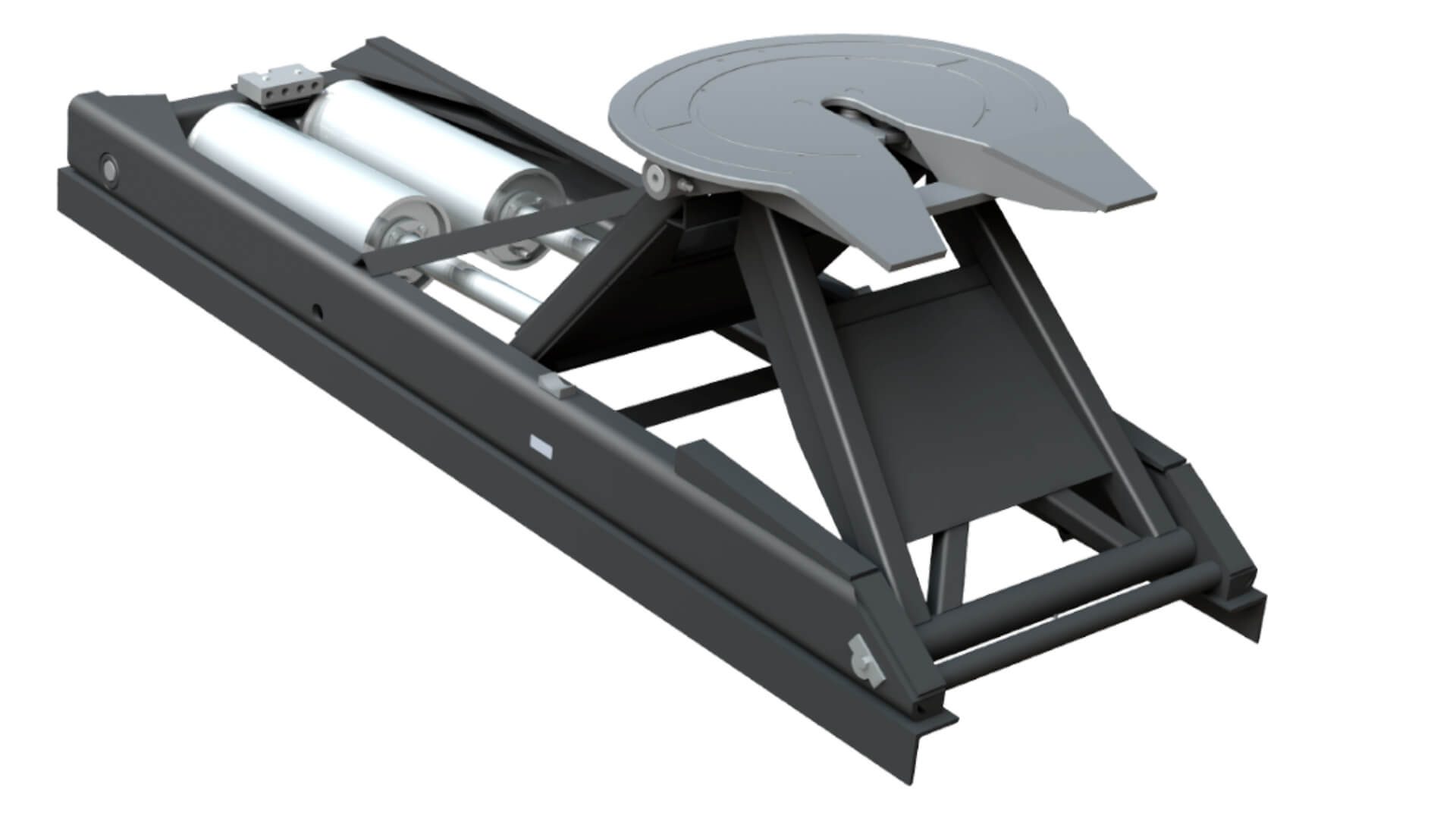
The Model 408 integrated boom and wheel lift is available with manual "L" arms or Chevron’s popular AutoGrip II™ wheel lift system that allows the retainer arms to hydraulically rotate from fully closed to an open approach position and then rotate, tightly gripping the vehicle tires. Other options include single or dual 9,000 lb planetary winches, a hydraulic telescoping recovery boom, conventional carbon steel or the new lighter weight aluminum modular body with stylish composite rear quarter fender panels.

Most automotive shops use hydraulic lifting equipment for raising vehicles to a comfortable working height for better productivity when they are serviced. The focus for this document will be on 4 post car lifts.
The drive-on four post car lift comes in several styles that are design specific to improve the user’s certain needs. One style that has gained in recent popularity is built for the car enthusiasts and collector car market. It has its own style that allows for servicing and storing cars on top and below the runways. This allows the enthusiast to use his shop space more efficiently without the expense of adding on to his shop. Not only do they provide more storage space, but just like the professional service centers, jacks can be added to these lifts to provide for wheels free service. The enthusiasts drive-on lifts also come in a variety of sizes that can allow enough height under the runways for a full size truck or SUV if needed.
Another popular style of drive-on lift is the commercial grade 14,000 lb. capacity lift. The dimensional range of this style is popular with independent repair shops as well as car dealerships because it can handle a wide range of vehicles without changing any setup. Runways are typically bolted into place at a width that accommodates narrow vehicles and are also wide enough to handle wider tread widths. This makes setup time minimal which leads to a more productive work bay.
1)A vehicle can be raised safely even when its engine has been removed. Trying to lift such a vehicle on a frame contact lift can be dangerous because the center of gravity has been changed and the load could become unbalanced.
Another popular application for the commercial grade 4-post lift is wheel alignment service. The cable style lift has independent locking ladders in each column that allow for precise leveling at each corner which is critical for accurately measuring wheel alignment angles. Once levelled, these lifts can simply be raised to the preferred height and set into the nearest locked position for a precise level condition. The alignment versions of these lifts can be equipped with front turntables and rear slip plates to allow complete four wheel alignment service. Add two roller jacks and both the front and rear can be raised to access all four wheels. Some models have an “open-front”, meaning the front crossrail has been removed to allow easy access under the front end without having the beam in your way.
On a wheel contact lift, the wheels are supported unless a wheel-free roller jack is used. These jacks, which are air powered and/or hydraulic, are used to raise either the front or rear of the car for wheels free work. After the vehicle is raised, the jack is lowered onto a mechanical safety latch. When using one of these jacks, keep hands clear and be sure to extend each of the lift arms an equal amount to avoid uneven loading. Be sure that a wheels free jack is lowered all of the way before driving into or out of the lift.
Above ground surface mount lifts became popular in the 1970’s. They are mounted completely above the concrete floor. Different lifts have different concrete requirements. Most surface mount lifts require a minimum of 4” depth concrete with a minimum compressive strength of 3000 PSI to support the lift columns and/or anchor bolts (Enthusiast style lifts do not require anchoring, but can still be anchored if desired). Lifts with higher rated capacities can require a minimum of 6” depth of concrete. Anchor bolts must be torqued to the manufacturer’s specification and checked periodically according to the maintenance guide in the lift’s manual. There are also specifications for the minimum amount of depth the anchor bolt needs to be embedded in the concrete. For example, most 4-post lifts up to 14,000 lb. capacities will require an anchor bolt that is 5.5” length by either ⅝” or ¾” width with a minimum embedment depth of 3.25”. This means once the bolt is torqued to spec, the minimum amount above the floor must be no more than 2.25” to achieve the minimum of 3.25” embedment. Follow the particular lift models manual for exact dimensions.
Ease of installation is one advantage of surface mount lifts. They are also relatively portable (enthusiast models are portable without anchors) and can be relocated in another location in case a business or shop owner decides to move to another location. They also do not have the problem of pollution of the ground water like an in-ground lift, if a hydraulic fluid leak occurs.
A surface mount lift is also easier to maintain or repair because it requires no excavation. Surface mount lifts are also less likely to leak oil into the ground (an environmental concern).
One of the most popular types of surface mounted lifts is the four-post wheel engaging type. It has four posts, two lifting crossrails, each one supporting two drive-on runways. The crossrails are synchronized so that they travel as level and together as possible. To keep the two crossrails moving together, steel cables, chain, synchronized motors or hydraulic circuits are used. The most common synchronization type in the USA is the steel cable.
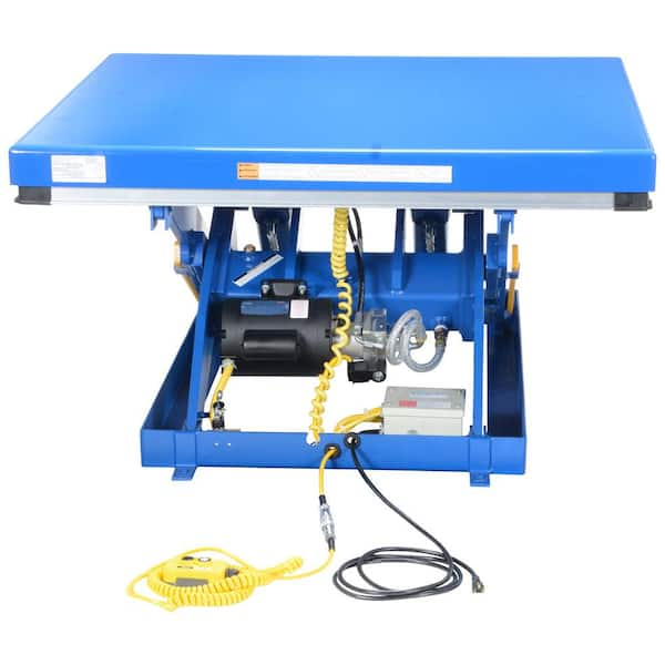
The lifting cables are attached to each post by routing from the hydraulic cylinder block through the powerside runway then distributed by a series of pulleys to each post. The cables carry the lift load and distribute it evenly to each column. The load is borne by the cylinder, cables, crossrails, columns and runways. Adjusting the cables and lock ladders at each column allows the safety locks and runways to be level and the safety locks to engage at the same time. A secondary safety lock system is used on the most current styles that are certified. This secondary lock system will lock into place in the event of a slack cable condition. Each of the 4 cables has its own safety lock system. The hydraulic system consist of an electric power unit, hydraulic hose and cylinder. The power unit includes the electric motor, pump and reservoir tank all in one unit.
The electric motor requires either 110 or 220 volt power on a 30 amp circuit. Most shops will prefer to drop the power down from the ceiling for hookup to the motor switch box as per local code. The 110 volt power units are supplied with the standard male plug with a short cord. The hydraulic pump is mounted between the motor and the reservoir tank. The pump is equipped with valves that have preset pressure limits to prevent lifting over the rated capacity. DO NOT ATTEMPT TO ADJUST THE FACTORY SETTINGS OF THE PRESSURE VALVE. When the up button is pressed the fluid is pressurized and sent along the hose to the cylinder to provide lift to the cables, crossrails and runways. The pump also has a lowering valve that is activated by the down lever. The down valve allows the fluid to return to the reservoir tank while lowering the lift.
To install a 4 post lift, it’ll be best to follow specific product instructions found in the manual. Your manual will guide you through the entire process of installation. Otherwise, consider reaching out to have your lift professionally installed. Having a team of professionals take on the feat of putting together your lift can save you time and effort, and if you don’t have a team of volunteers to help you raise your lift to a vertical position, you’ll need the manpower.
When you search for this question, you’ll receive different answers depending on the product people are referring to. The best answer is to check the lift’s manual since not all 4 post lifts need to be anchored. Some 4 post lifts are free standing while commercial grade 4 post lifts come with anchors and bolts to mount the lift on a concrete floor.
Training in the proper use of the lift is mandatory before attempting to lift a car. Although lifts have an excellent safety record, vehicles can be loaded improperly. When a vehicle comes down by accident, this is usually due to carelessness, misuse, or neglected maintenance. The American National Standards Institute (ANSI) and the Automotive Lift Institute (ALI) have set the American National Standard (ANSI/ALI ALOIM - Sept 2008) for automotive lifts. This standard list safety requirements for operation, inspection, and maintenance of lifts. It requires annual lift inspection by a qualified lift inspector. ALI is also working on a new certification for lift inspectors. This annual inspection is designed to keep automotive lifts in good operating condition. For more information visit the ALI website www.autolift.org.
Safety Note-Remember that you are lifting a vehicle that weighs several thousand pounds. The car must be correctly spotted on the lift. When driving a vehicle onto a wheel contact lift, be sure that the front tires are centered, at equal distances from the edges of the ramps. These lifts have secondary stops for roll-off protection at the front and rear. After spotting the vehicle, always use manual wheel chocks to prevent the car from rolling.
Safety Note-The weight of the vehicle must be distributed evenly. If using a 9,000-lb. capacity 4-post lift, each end of the lift is rated for 4,500-lbs. Do not overload one end of the lift.
All lifts have a safety latch system to be used once the desired lift height is reached. Always lower the lift into the locked position before going under the vehicle. Never use a lift that not able to engage the safety latch system. Tall jack stands are often used to assist load changes while working on a lift.
The lift area should be clean with no grease or oil on the floor. Hoses, extension cords, and tools should be stored in the places where they belong.
Be sure that the lift has adequate capacity to lift the weight of the vehicle. If the vehicle contains any loads inside, in the trunk, or in the bed of a truck, the center of gravity will be affected and the vehicle may be unsafe to lift.

1 Ability to lift 3000 kg capacity 10 3 1 2 2 2 2 2 1 1 1
3 Load lifting 10 2 1 3 1 2 1
5 Safe lifting 10 2 2 2 2 3 2 2 1 1 2 2
8 Smooth lifting 8 1 2 2 3 2 1
Check that the pump shaft is rotating. Even though coupling guards and C-face mounts can make this difficult to confirm, it is important to establish if your pump shaft is rotating. If it isn’t, this could be an indication of a more severe issue, and this should be investigated immediately.
Check the oil level. This one tends to be the more obvious check, as it is often one of the only factors inspected before the pump is changed. The oil level should be three inches above the pump suction. Otherwise, a vortex can form in the reservoir, allowing air into the pump.
What does the pump sound like when it is operating normally? Vane pumps generally are quieter than piston and gear pumps. If the pump has a high-pitched whining sound, it most likely is cavitating. If it has a knocking sound, like marbles rattling around, then aeration is the likely cause.
Cavitation is the formation and collapse of air cavities in the liquid. When the pump cannot get the total volume of oil it needs, cavitation occurs. Hydraulic oil contains approximately nine percent dissolved air. When the pump does not receive adequate oil volume at its suction port, high vacuum pressure occurs.
This dissolved air is pulled out of the oil on the suction side and then collapses or implodes on the pressure side. The implosions produce a very steady, high-pitched sound. As the air bubbles collapse, the inside of the pump is damaged.
While cavitation is a devastating development, with proper preventative maintenance practices and a quality monitoring system, early detection and deterrence remain attainable goals. UE System’s UltraTrak 850S CD pump cavitation sensor is a Smart Analog Sensor designed and optimized to detect cavitation on pumps earlier by measuring the ultrasound produced as cavitation starts to develop early-onset bubbles in the pump. By continuously monitoring the impact caused by cavitation, the system provides a simple, single value to trend and alert when cavitation is occurring.
The oil viscosity is too high. Low oil temperature increases the oil viscosity, making it harder for the oil to reach the pump. Most hydraulic systems should not be started with the oil any colder than 40°F and should not be put under load until the oil is at least 70°F.
Many reservoirs do not have heaters, particularly in the South. Even when heaters are available, they are often disconnected. While the damage may not be immediate, if a pump is continually started up when the oil is too cold, the pump will fail prematurely.
The suction filter or strainer is contaminated. A strainer is typically 74 or 149 microns in size and is used to keep “large” particles out of the pump. The strainer may be located inside or outside the reservoir. Strainers located inside the reservoir are out of sight and out of mind. Many times, maintenance personnel are not even aware that there is a strainer in the reservoir.
The suction strainer should be removed from the line or reservoir and cleaned a minimum of once a year. Years ago, a plant sought out help to troubleshoot a system that had already had five pumps changed within a single week. Upon closer inspection, it was discovered that the breather cap was missing, allowing dirty air to flow directly into the reservoir.
A check of the hydraulic schematic showed a strainer in the suction line inside the tank. When the strainer was removed, a shop rag was found wrapped around the screen mesh. Apparently, someone had used the rag to plug the breather cap opening, and it had then fallen into the tank. Contamination can come from a variety of different sources, so it pays to be vigilant and responsible with our practices and reliability measures.
The electric motor is driving the hydraulic pump at a speed that is higher than the pump’s rating. All pumps have a recommended maximum drive speed. If the speed is too high, a higher volume of oil will be needed at the suction port.
Due to the size of the suction port, adequate oil cannot fill the suction cavity in the pump, resulting in cavitation. Although this rarely happens, some pumps are rated at a maximum drive speed of 1,200 revolutions per minute (RPM), while others have a maximum speed of 3,600 RPM. The drive speed should be checked any time a pump is replaced with a different brand or model.
Every one of these devastating causes of cavitation threatens to cause major, irreversible damage to your equipment. Therefore, it’s not only critical to have proper, proactive practices in place, but also a monitoring system that can continuously protect your valuable assets, such as UE System’s UltraTrak 850S CD pump cavitation senor. These sensors regularly monitor the health of your pumps and alert you immediately if cavitation symptoms are present, allowing you to take corrective action before it’s too late.
Aeration is sometimes known as pseudo cavitation because air is entering the pump suction cavity. However, the causes of aeration are entirely different than that of cavitation. While cavitation pulls air out of the oil, aeration is the result of outside air entering the pump’s suction line.
Several factors can cause aeration, including an air leak in the suction line. This could be in the form of a loose connection, a cracked line, or an improper fitting seal. One method of finding the leak is to squirt oil around the suction line fittings. The fluid will be momentarily drawn into the suction line, and the knocking sound inside the pump will stop for a short period of time once the airflow path is found.
A bad shaft seal can also cause aeration if the system is supplied by one or more fixed displacement pumps. Oil that bypasses inside a fixed displacement pump is ported back to the suction port. If the shaft seal is worn or damaged, air can flow through the seal and into the pump’s suction cavity.
As mentioned previously, if the oil level is too low, oil can enter the suction line and flow into the pump. Therefore, always check the oil level with all cylinders in the retracted position.
If a new pump is installed and pressure will not build, the shaft may be rotating in the wrong direction. Some gear pumps can be rotated in either direction, but most have an arrow on the housing indicating the direction of rotation, as depicted in Figure 2.
Pump rotation should always be viewed from the shaft end. If the pump is rotated in the wrong direction, adequate fluid will not fill the suction port due to the pump’s internal design.
A fixed displacement pump delivers a constant volume of oil for a given shaft speed. A relief valve must be included downstream of the pump to limit the maximum pressure in the system.
After the visual and sound checks are made, the next step is to determine whether you have a volume or pressure problem. If the pressure will not build to the desired level, isolate the pump and relief valve from the system. This can be done by closing a valve, plugging the line downstream, or blocking the relief valve. If the pressure builds when this is done, there is a component downstream of the isolation point that is bypassing. If the pressure does not build up, the pump or relief valve is bad.
If the system is operating at a slower speed, a volume problem exists. Pumps wear over time, which results in less oil being delivered. While a flow meter can be installed in the pump’s outlet line, this is not always practical, as the proper fittings and adapters may not be available. To determine if the pump is badly worn and bypassing, first check the current to the electric motor. If possible, this test should be made when the pump is new to establish a reference. Electric motor horsepower is relative to the hydraulic horsepower required by the system.
For example, if a 50-GPM pump is used and the maximum pressure is 1,500 psi, a 50-hp motor will be required. If the pump is delivering less oil than when it was new, the current to drive the pump will drop. A 230-volt, 50-hp motor has an average full load rating of 130 amps. If the amperage is considerably lower, the pump is most likely bypassing and should be changed.
Figure 4.To isolate a fixed displacement pump and relief valve from the system, close a valve or plug the line downstream (left). If pressure builds, a component downstream of the isolation point is bypassing (right).
The most common type of variable displacement pump is the pressure-compensating design. The compensator setting limits the maximum pressure at the pump’s outlet port. The pump should be isolated as described for the fixed displacement pump.
If pressure does not build up, the relief valve or pump compensator may be bad. Prior to checking either component, perform the necessary lockout procedures and verify that the pressure at the outlet port is zero psi. The relief valve and compensator can then be taken apart and checked for contamination, wear, and broken springs.
Install a flow meter in the case drain line and check the flow rate. Most variable displacement pumps bypass one to three percent of the maximum pump volume through the case drain line. If the flow rate reaches 10 percent, the pump should be changed. Permanently installing a flow meter in the case drain line is an excellent reliability and troubleshooting tool.
Ensure the compensator is 200 psi above the maximum load pressure. If set too low, the compensator spool will shift and start reducing the pump volume when the system is calling for maximum volume.
Performing these recommended tests should help you make good decisions about the condition of your pumps or the cause of pump failures. If you change a pump, have a reason for changing it. Don’t just do it because you have a spare one in stock.
Conduct a reliability assessment on each of your hydraulic systems so when an issue occurs, you will have current pressure and temperature readings to consult.
Al Smiley is the president of GPM Hydraulic Consulting Inc., located in Monroe, Georgia. Since 1994, GPM has provided hydraulic training, consulting and reliability assessments to companies in t...

We are so confident that you will agree that we will guarantee your satisfaction. If you are going to install it. We ship it out in a wooden crate. Comes with everything needed to install: Tow Light Plug, Work Lights, Wired Tow Lights, Ratchets, Straps, Safety Chains, Power Wire and the controller is pre-wired to the pump for easy installation.
The installation is professional. 2nd battery is provided when using an Electric/Hydraulic Pump. Fuses and circuit breakers are installed along with a tool box enclosure to protect the Electric/Hydraulic Pump.
We used cutting-edge CAD technology to create the design to build the strongest, most versatile wheel lift on the market. Our team constructs each piece, by hand, to ensure solid construction and strength at all connections. We have strategically reinforce areas that are known to have issues in other designs, to prevent weak spots from occurring. We also strategically reinforce the truck frame before mounting the Lil Hercules™ wheel lift. Lil’ Hercules comes as either standard “L” arm-wheel grid, or the self-loading Herc-O-Matic.
Our Lil Hercules™ product line is the leader in underbody wheel lifts, showing up the competition at every turn. Despite its incredibly strong & durable construction, our Lil Hercules™ boasts a 5,000lb lift capacity, 10,000lb towing capacity, and a 70″ reach capacity, Our ultra-tough design allows for heavy duty workload from a lighter duty vehicle, without compromising the vehicle’s comfort. Our units enable its clients to kill 2 birds w/ one stone. Transforming their personal truck into a work truck at anytime they choose. $aving time is making $$$.
The Lil Hercules™ features a 12 volt pump with an 8 minute duty cycle (that’s 4 TIMES stronger than industry standard issue). All of our pivot points are fabricated in-house, and constructed with our unique two-piece hexagonal nut-and-bolt design pin system, and our signature oil-infused bronze bushings. These require less maintenance than other pivot point systems, because the bushings literally sweat oil. Our pivot points are the strongest on the market, and will never corrode and freeze up. They last longer, require less maintenance, and are backed by a lifetime warranty. That means you spend your time on the road making money, instead of in the shop, paying for repairs.
If you have a Lil Hercules™ or Herc-O-Matic installed on the back of your truck, you’ll enjoy our adjustable nut-and-bolt pivot pin. Instead of the traditional construction of a one-piece 1018 steel pin for the pivot head on a wheel lift, we use a two-piece, heavy-duty hexagonal bolt that can be tightened into its nut. That means not having to come into the shop and pay for service and replace that little pin every few years. Instead, as it loosens, you can quickly and easily give it an adjustment, and carry on carrying on.


 8613371530291