
white hydraulic pump parts free sample
Select Make AGCO Agracat Agri-Power Allis Chalmers Avery Belarus Bobcat Bolens Branson Case Case IH Century Challenger CockShutt / CO OP County Cub Cadet David Brown Deutz Deutz Allis Farm Pro Farmtrac Fendt FIAT Ford Foton Hesston Hinomoto International Iseki JCB Jinma John Deere Kama Kioti Kubota Kukje Kumiai Landini Leyland Long LS Mahindra Massey Ferguson Massey Harris McCormick Minneapolis Moline Mitsubishi Montana New Holland Nuffield Oliver Renault Rhino Same Satoh Shenniu Shibaura Steiger Steyr TYM Universal Valmet Valtra Versatile White Yanmar Zetor

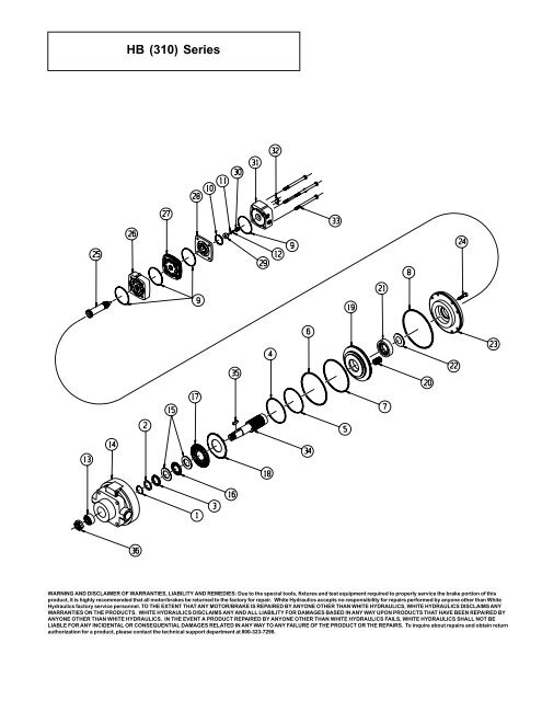
Compatible with White Tractor(s) 2-85 (s/n 289228-296877), 2-88, 2-105, 2-110, 2-115, 2-180, 4-175, 4-210, 4-225, 4-270, 100, 120, 125, 145, 160, 170, 185, 195

We can repair many of the White motors. Send in your Motor for inspection and evaluation. Let us repair your White hydraulic motor instead of replacing it. All our repairs, including our White hydraulic motor repairs, are warrantied and ready for reinstallation.Contact usfor more information about our hydraulic repair services.
Looking to get your White Hydraulics pump unit repaired or looking to purchase a new White Hydraulics pump? Precision Fluid Power sells re-manufactured and new White hydraulics – White hydraulics pumps, White hydraulics valves, and White hydraulics motors. Additionally, Precision Fluid Power offers expert level hydraulic pump repair services for many brands, including White Hydraulics. Search our online catalog or contact us and let us know how we can help you.
We can supply what you need or repair what you have. Before purchasing, there may be a good chance that your current White Hydraulics pump, motor, valve or cylinder can be repaired. White hydraulics pump repairs, including motors, valves & cylinders comes with our two year warranty.
When purchasing, consider White hydraulics re-manufactured or after-market hydraulic units. Best of all they can get you back up and running for less than the cost of a new hydraulic unit. We will give you a free quote so you can compare costs for a new, repaired or reman White unit.
White Hydraulics is headquartered in Hopkinsville, Kentucky. Starting in 1966, their first patent was issued for the Hydraulic Orbital Gerotor Motor (HOGM). In 1990 the 1st US HOGM Manufactured became ISO-9002 certificated. Manufacturing reached new heights in 1996 with 2 million of the White hydraulic motors shipped. In 2005 White Hydraulics became White Drive Products. Demand continued to grow with 2015 seeing 10 million of White hydraulic motors shipped. In 2017 the White Drive Products become a part of the Danfoss Group.
The over-pressurization of hydraulic pumps and motors can have severe negative effects on your hydraulic system. Hydraulic pumps are designed to function at a specific pressure levels and flow rates. Hydraulic motors are also designed to work within specific parameters and therefore it is essential to ensure that recommended continuous flows and pressures are not exceeded any more than specified by the manufacturer. Forcing hydraulic components to work outside these parameters can harm your equipment and possibly bring about total system failure.
When there is an increase, beyond the pump design maximum pressure, in the hydraulic system, it will result in pump over-pressurization. If this happens, it can also have a domino effect on other hydraulic parts and components within the system.
Over-pressurization adds increased pressure on motors, cylinders, hoses, and other system components. This can lead to an increased rate of wear and tear leading them to fail prematurely. The excess pressure can also cause buckling of smaller metal parts and components, such as cylinder rods, leading to catastrophic system failure.
Certain parts in the system can begin to come apart because of the excessive pressure. O-rings, hose connections, pumps and other parts may burst. For example: hydraulic gear pump front and rear covers can distort or the bolts holding the pumps together can stretch or strip the threads from too much pressure in the system. High pressure due to excessive load on orbital motors can cause them to seize causing damage to the spools and or causing internal shaft breakage.
Pumps, motors, and other moving components rely on the lubrication qualities of the hydraulic fluid to ensure, due to the very tight clearances between moving parts, proper functionality. Increased pressure on the rotating component in question will tend to throw shafts slightly out of normal balance reducing the clearance on one side of the shaft whilst increasing it on the load side. This has the twin effect of encouraging leakage from the pressure side whilst also causing metal to metal contact on the low pressure side as there is insufficient clearance for lubrication leading to hydraulic leaks, component abrasion, boundary lubrication, and other undesirable effects. This results in premature wear and even system failure.
The best way to prevent over-pressurisation effects is to avoid operating a hydraulic system beyond its recommended pressure level and to perform regular hydraulic system maintenance, ensuring maximum pressure levels are properly maintained. If a system is regularly over-pressurised, it is an indication that it is not designed correctly to match the operational requirements and it may be necessary to use larger capacity cylinders, motors or pumps.
Perform routine check-ups- Simply inspecting your hydraulic pressure pumps, switches, control valves, and other components on a routine basis can prevent many problems before they lead to serious damage.
Check pressure relief settings- This is especially important when installing a new pump. Replacing a worn-out pump with a larger version often results in more flow than the hydraulic system is designed to handle.
Make sure case drain lines return direct to tank- Pump and motor Case Drain lines should return directly to tank via lines that exert as close to zero back pressure. If using a return filter ensure that it is over sized so that there is no back pressure being exerted by it. It is probably best unless the pressure on the case drain is monitored very regularly to return the case drain lines directly to tank without a filter as the damage that can be caused due to excessive case drain pressure is probably greater than the amount of potential contamination that might be caught by a filter in this case.
If you wish to purchase high-quality hydraulic pumps and motors and related hydraulic system components, or need help designing a customized pump and motor configuration, please feel free to contact White House Products, Ltd., at +44 (0) 1475 742500 today!

Dynamic BMER-1 motors have proven over time to be an excellent drop-in replacement for the White Drive Products 500 series motors, but we knew we could do better. So, the standard BMER-1 motors will be plased out and slowly replaced by the new BMER-2 motors. With the additional side load capacity, as well as, the addition of several larger diameter shaft options, the BMER-2 motors will now serve as drop-in replacements for both the White 500 and 530 series.
Dynamic will continue to support, service, and offer seal kits for the BMER-1 motors for as long as our manufacturer continued to stock the necessary parts.
Send us your pump or motor for a free evaluation. We will carefully clean and inspect it, checking precision fits for tolerance and listing necessary replacement parts.
Pumps are generally grouped into two broad categories—positive displacement pumps and dynamic (centrifugal) pumps. Positive displacement pumps use a mechanical means to vary the size of (or move) the fluid chamber to cause the fluid to flow. On the other hand, centrifugal pumps impart momentum to the fluid by rotating impellers that are immersed in the fluid. The momentum produces an increase in pressure or flow at the pump outlet.
Positive displacement pumps have a constant torque characteristic, whereas centrifugal pumps demonstrate variable torque characteristics. This article will discuss only centrifugal pumps.
A centrifugal pump converts driver energy to kinetic energy in a liquid by accelerating the fluid to the outer rim of an impeller. The amount of energy given to the liquid corresponds to the velocity at the edge or vane tip of the impeller. The faster the impeller revolves or the bigger the impeller, then the higher the velocity of the liquid at the vane tip and the greater the energy imparted to the liquid.
Creating a resistance to the flow controls the kinetic energy of a liquid coming out of an impeller. The first resistance is created by the pump volute (casing), which catches the liquid and slows it down. When the liquid slows down in the pump casing, some of the kinetic energy is converted to pressure energy. It is the resistance to the pump’s flow that is read on a pressure gauge attached to the discharge line. A pump does not create pressure, it only creates flow. Pressure is a measurement of the resistance to flow.
In Newtonian (true) fluids (non-viscous liquids, such as water or gasoline), the term head is the measurement of the kinetic energy that a centrifugal pump creates. Imagine a pipe shooting a jet of water straight into the air. The height that the water reaches is the head. Head measures the height of a liquid column, which the pump could create resulting from the kinetic energy the centrifugal pump gives to the liquid. The main reason for using head instead of pressure to measure a centrifugal pump’s energy is that the pressure from a pump will change if the specific gravity (weight) of the liquid changes, but the head will not change. End users can always describe a pump’s performance on any Newtonian fluid, whether it is heavy (sulfuric acid) or light (gasoline), by using head. Head is related to the velocity that the liquid gains when going through the pump.
All the forms of energy involved in a liquid flow system can be expressed in terms of feet of liquid. The total of these heads determines the total system head or the work that a pump must perform in the system. The different types of head—friction, velocity and pressure—are defined in this section.
Pressure head must be considered when a pumping system either begins from or empties into a tank that is under some pressure other than atmospheric. The pressure in such a tank must first be converted to feet of liquid. A vacuum in the suction tank or a positive pressure in the discharge tank must be added to the system head, whereas a positive pressure in the suction tank or vacuum in the discharge tank would be subtracted. The following is a formula for converting inches of mercury vacuum into feet of liquid:
The different types of head are combined to make up the total system head at any particular flow rate. The descriptions in this section are of these combined or dynamic heads, as they apply to the centrifugal pump.
Total dynamic suction lift is the static suction lift minus the velocity head at the pump suction flange plus the total friction head in the suction line. The total dynamic suction lift, as determined on a pump test, is the reading of a gauge on the suction flange, converted to feet of liquid and corrected to the pump centerline, minus the velocity head at the point of gauge attachment.
Total dynamic discharge head is the static discharge head plus the velocity head at the pump discharge flange plus the total friction head in the discharge line. The total dynamic discharge head, as determined on pump test, is the reading of a gauge at the discharge flange, converted to feet of liquid and corrected to the pump centerline, plus the velocity head at the point of gauge attachment.
Suction liftexists when the source of supply is below the centerline of the pump. Therefore, the static suction liftis the vertical distance in feet from the centerline of the pump to the free level of the liquid to be pumped.
Suction headexists when the source of supply is above the centerline of the pump. Therefore, the static suction headis the vertical distance in feet from the centerline of the pump to the free level of the liquid to be pumped.
Static discharge headis the vertical distance in feet between the pump centerline and the point of free discharge or the surface of the liquid in the discharge tank.
The work performed by a centrifugal pump is a function of the total head and the weight of the liquid pumped in a given time period. The pump capacity in gallons per minute and the liquid specific gravity are normally used in the formulas rather than the actual weight of the liquid.
Pump input or brake horsepower (BHP) is the actual horsepower delivered to the pump shaft. Pump output or water horsepower (WHP) is the liquid horsepower delivered by the pump. These two terms are defined by the following formulas:
Pump characteristics—such as flow, pressure, efficiency and brake horsepower—are shown graphically on a pump curve. The first item to look at is the size of the pump. The size of the pump, 2x3-8 is shown in the upper section of the graph. The numbers 2x3-8 indicates:
Some companies may have the number shown as 3x2-8. The larger of the first two numbers is the inlet. Pump speed (rpm) is also shown in the upper section of the graph and indicates performance at a speed of 3,560 rpm. All the information is representative of this operational speed.
The left side of the performance curve shows the head (feet) generated at the different flow rates. Multiple flow versus head curves are present on the graph (see Figure 3). Each one represents a different (trimmed) impeller size. For this pump, the range of impellers is 5.5 inches to 8.375 inches.
Efficiency curves are overlaid on the graph (vertical lines) and indicate from 64 to 45 percent efficiency for this pump. As head is increased, flow and efficiency decrease.
The pump curve is solely a function of the physical characteristics of the pump. The system curve is completely dependent on the size of pipe, the length of pipe, the number and location of elbows, and other factors. Where these two curves intersect is the natural operating point (see Figure 4). This is where the pump pressure matches the system losses and everything is balanced.
If the system is part of a process that changes often or continuously, then some method of altering the pump characteristics or the system parameters is necessary. Two methods can accomplish the continuously varying flow objective. One method is throttling, which changes the system curve by use of a control or throttling valve. The other method is to vary the speed of the pump, which modifies the pump curve.
For comparison, let’s use an example to determine the power requirements for the throttling system, then the variable speed system. A pump (with an 8-inch impeller) operating at a base speed of 3,560 rpm is used. This pump is to operate a system requiring a 250-foot head at 250 gpm (see Figure 6).
In comparison, the variable speed method takes advantage of the change in pump characteristics that occur when the impeller speed is changed (see Figure 7). The lower pump speed changes the pump curve based on the head generated by the velocity of the fluid being pumped. Remember that the head is equal to V2/2g.
A set of formulas that is used to predict the operation of a centrifugal pump at any operating point based on the original pump characteristics is known as the affinity laws.
Use the affinity laws to calculate the values for the remainder of the operating points. Obviously, varying the speed requires much less power. To determine the actual power required, the efficiency of the drive should be factored in. The energy savings will depend on the amount of time the pump is operated at each reduced speed point.
To calculate the actual savings, the brake horsepower must be converted to watts and then multiplied by the hours of operation. The result is then multiplied by the cost per kilowatt hour to show the cost to operate the pump at each flow point. Subtract the variable speed value from the throttling value to show the difference in energy cost.
This article illustrates how centrifugal pumps’ inherent nature of operation makes them prime candidates for energy savings. Most pump systems are designed and oversized for worst-case loading conditions. Following the principle of the affinity laws, just by lowering the flow of an oversized centrifugal pump by 20 percent can reduce power consumption by about 50 percent, resulting in dramatic energy savings.


 8613371530291