
why is my hydraulic pump overheating free sample

You can use multiple different upgrades and tuning methods on hydraulic systems. Many users will invest in upgrades that promise more flow and speed. The issue with these upgrades is that they"re not always fit for the hydraulic systems they"re applied to.
Since everything needs to stay in balance, you must make sure your upgrades match the entirety of your hydraulic system. For example, a higher flow pump can help give increased capabilities to a hydraulic system, but did you also check to see if the system"s hoses and piping can handle that increase in flow?
The increased flow can hit your smaller hoses hard and require more pressure just to get through them. This goes for any part of the hydraulic system that isn"t readily capable of handling more flow.
When you make upgrades, also ascertain if you need to change other components. In the example of the higher flow pump, you can simply increase your hose size, and that makes all the difference.
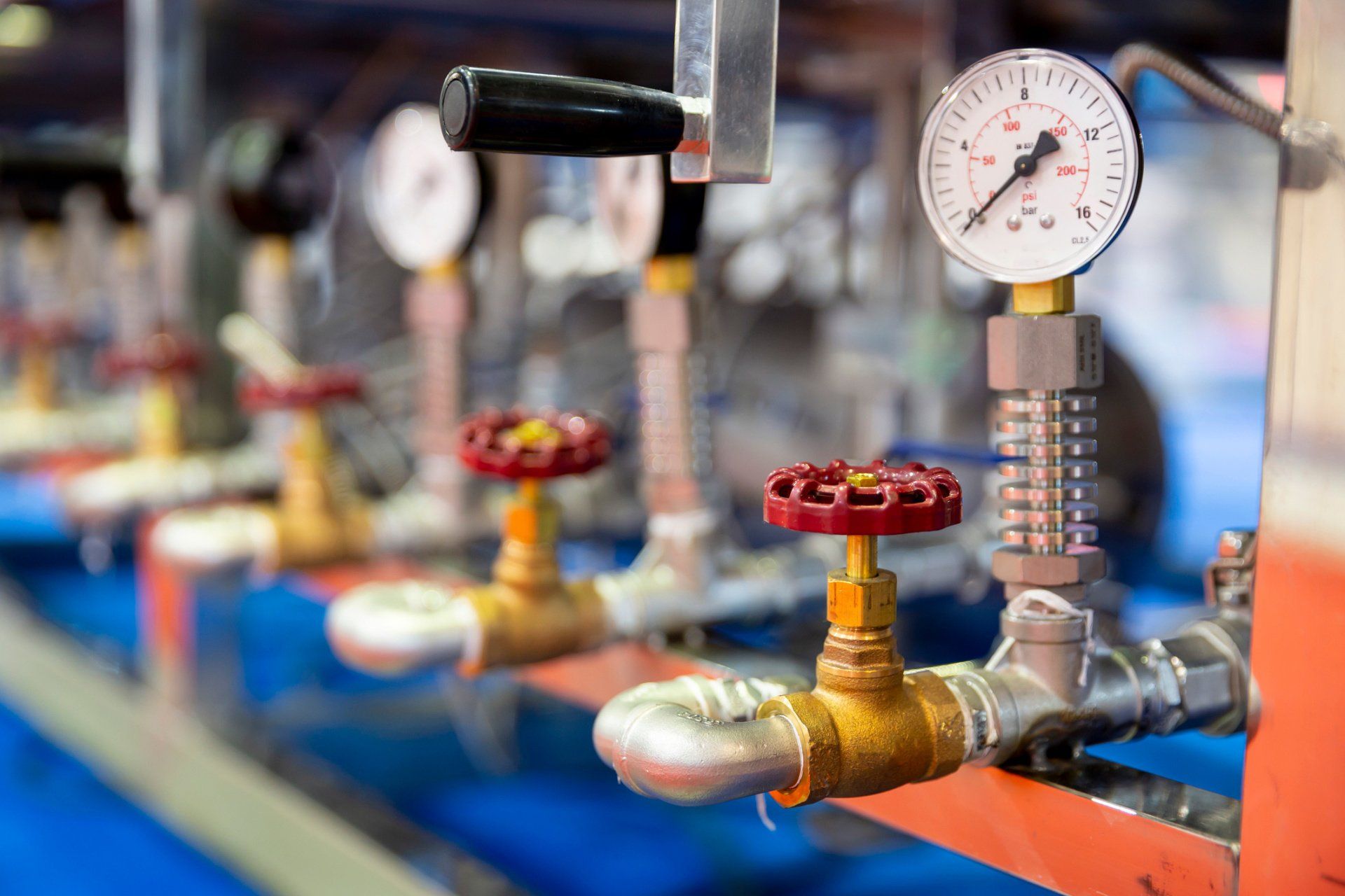
Is your hydraulic pump getting excessively hot during normal operation? Pumps do generate heat when running, however they are designed with specific heat parameters in mind. Overheating is an abnormal condition that leads to destructive issues such as thinning of hydraulic fluid, which leads to reduced lubrication, metal-on-metal contact of moving parts. And accelerated pump wear and failure.
Therefore it is never a good idea to ignore a pump that is exceeding its heat parameters under normal load. There are a number of factors that contribute to an excess buildup of heat and in this article, we’ll explain some of these issues.
Hydraulic fluid viscosity refers to the thickness or “resistance to pouring” of your hydraulic fluid. This is very important to the correct operation of your pump. The fluid not only transmits the power that moves your drives and actuators. It also lubricates internal components and removes heat from the system. Hydraulic fluid is designed to operate at a specific temperature range. As it heats, it becomes thinner and eventually it will lose the ability to lubricate moving parts. The increased friction may cause the pump to heat up, and naturally increased wear will be taking place when this is happening. On the other hand, hydraulic fluid that is too thick flows less efficiently within the system, which also results in heat buildup.
Fluid that is contaminated with dirt, debris, water and other impurities may cause heat build up in a few ways. Blocked fluid filters, pipes and strainers place undue load on the pump or even lead to pressure drops on the back side of filters that cause cavitation.
Low fluid levels can result in a condition in which not enough flow is reaching the critical hydraulic components and moving parts. This is known as oil starvation and just like running your car without oil, it will increase metal-on-metal friction and lead to increased heat and wear. Oil starvation can also be caused by clogged hydraulic filters, incorrect fluid reservoir design.
Cavitation is the rapid formation and implosion of air cavities in the hydraulic fluid. When these air cavities collapse under pressure, they generate a lot of heat. In fact, temperatures can reach up to 2700 degrees C at the point of implosion! Not only does cavitation compromise the lubrication properties of the oil, the excessive heat that is generated is extremely damaging to the hydraulic pump and the system as a whole. Attacking hoses and seals and causing metal components to expand and wear.
This happens when air makes its way into the system via air leaks at points like pump seals, and pipe fittings. And what happens next in a hydraulic system? Compression! Air generates heat when compressed, which naturally leads to an increase in temperature if left untreated. In extreme circumstances it can also lead to ‘hydraulic dieseling’ whereby compressed air bubbles actually explode in the same process that powers diesel engines. This is not good and leads to degradation of the fluid and damage to system components through loss of lubrication and burning of seals.
As pumps wear, the internal leakage or “slippage” increases. Essentially, fluid is able to make its way past tight fitting components, which reduces the efficiency of the pump, but in addition, as this occurs, fluid moves from a high pressure to a low pressure without doing any mechanical work, since according to the laws of physics energy cannot be destroyed, it is instead converted into heat.
A build-up of excessive heat is a symptom of hydraulic pump problems, but it is far from the only signal that there may be something wrong. There are other important warning signs that you should pay attention to. These include unusual noises, pressure problems and flow problems. Each of these symptoms provide clues about any potential pump problems that need to be addressed - so it’s important to familiarise yourself with all of these issues. To help, we’ve created a downloadable troubleshooting guide containing more information about each of these issues. So that you can keep your system up and running and avoid unplanned downtime. Download ithere.
When hydraulic oil is getting overheated, there could be several common causes that also cause the system to overheat. First, it is crucial to understand the type of hydraulic system you are using to begin troubleshooting why the system is overheating.
The first cause of hydraulic oil overheating is when the hydraulic equipment system parts and components are nearing the end of their useful lifespans. As they degrade, due to increased internal leakage, they have to work harder to maintain the desired system pressure.
For example, your hydraulic pump is wearing out and needs to be replaced. Due to internal wear pressurised fluid escapes from the high pressure side to the low pressure side generating heat increasing the temperature of the hydraulic fluid and causing circuit overheating.
It is understood that you may want to make system upgrades or changes to customize the system to reflect your specific needs. However, when you do not consider the entire system, it can cause the system to work hard, give off more heat, and increase hydraulic oil temperatures, leading to circuit overheating.
For instance, you may want to increase the fluid flow rate through the system. However, you did not account for the size of hoses and tubing to accommodate the higher flow rates. As a result, the system has to work hard to force the increased flow rates through incompatible hoses and tubes, resulting in more heat generation and fluid overheating.
Tweaking your hydraulic system is perfectly acceptable to optimize its performance. However, where many people go wrong is they only adjust one part of the system and fail to think about how the adjustment will impact other parts of the system.
For example, suppose you make an adjustment to the pump compensator and increase the pressure yet fail to also make a similar adjustment to the relief valve. In this instance the relief valve will blow off more frequently generating more heat and therefore increasing the circuit fluid temperature.
Every component in a hydraulic system imposes a load on the pump, this is referred to as the pressure drop across the particular component. The figure will vary depending upon the flow rate and the energy lost from the fluid due to the pressure drop is converted into heat. If the overall pressure drop across all the components in the circuit unexpectedly increases so the heat generated across the circuit will also increase.
If the fluid is not cooled to compensate for this the fluid temperature continues to increase as the other parts and components generate excessive heat.
If there is dirt, sludge, debris, or water in the hydraulic fluid, the system will generate more heat as it attempts to compensate for the contaminants and push the fluid through the system. Therefore, it is always vital to check your fluid for contamination and change it and or improve fluid filtration when required.
After troubleshooting overheating problems, if you have determined it is not due to the four common causes mentioned above, then there are two general ways you can resolve fluid overheating problems. You can either increase the reservoir capacity to dissipate heat or decrease the amount of heat being generated by the system.
Another way to increase the heat dissipation is to inspect the current heat exchangers, if they are being used, and make the appropriate adjustments. In some cases, you may want to install additional heat exchangers to help reduce the fluid temperature.
To find hydraulic parts, components, and accessories to help you resolve hydraulic oil overheating problems, or if you require assistance in troubleshooting system overheating, please feel free to contact White House Products, Ltd. at +44 (0) 1475 742500 today!
Overheating ranks No. 2 in the list of most common problems with hydraulic equipment. Unlike leaks, which rank No. 1, the causes of overheating and its remedies are often not well understood by maintenance personnel
Heating of hydraulic fluid in operation is caused by inefficiencies. Inefficiencies result in losses of input power, which are converted to heat. A hydraulic system’s heat load is equal to the total power lost (PL) through inefficiencies and can be expressed as:
If the total input power lost to heat is greater than the heat dissipated, the hydraulic system will eventually overheat. Installed cooling capacity typically ranges between 25 and 40 percent of input power, depending on the type of hydraulic system.
How hot is too hot? Hydraulic fluid temperatures above 180°F (82°C) damage most seal compounds and accelerate degradation of the oil. While the operation of any hydraulic system at temperatures above 180°F should be avoided, fluid temperature is too high when viscosity falls below the optimum value for the hydraulic system’s components. This can occur well below 180°F, depending on the fluid’s viscosity grade.
To achieve stable fluid temperature, a hydraulic system’s capacity to dissipate heat must exceed its heat load. For example, a system with continuous input power of 100 kW and an efficiency of 80 percent needs to be capable of dissipating a heat load of at least 20 kW. Assuming this system has a designed cooling capacity of 25 kW, anything that increases heat load above 25 kW or reduces the cooling system’s capacity below 25 kW will cause the system to overheat.
Consider this example. I was recently asked to investigate and solve an overheating problem in a mobile application. The hydraulic system was comprised of a diesel-hydraulic power unit, which was being used to power a pipe-cutting saw. The saw was designed for sub-sea use and was connected to the hydraulic power unit on the surface via a 710-foot umbilical. The operating requirements for the saw were 24 GPM at 3,000 PSI.
The hydraulic power unit had a continuous power rating of 37 kW and was fitted with an air-blast heat exchanger. The exchanger was capable of dissipating 10 kW of heat under ambient conditions or 27 percent of available input power (10/37 x 100 = 27). The performance of all cooling circuit components were checked and found to be operating within design limits.
At this point it, was clear that the overheating problem was being caused by excessive heat load. Concerned about the length of the umbilical, I calculated its pressure drop. The theoretical pressure drop across 710 feet of ¾-inch pressure hose at 24 GPM is 800 PSI. The pressure drop across the same length of 1-inch return hose is 200 PSI. The theoretical heat load produced by the pressure drop across the umbilical of 1,000 PSI (800 + 200 = 1,000) was 10.35 kW. This meant that the heat load of the umbilical was 0.35 kW more than the heat dissipation capacity of the hydraulic system’s heat exchanger. This, when combined with the system’s normal heat load (inefficiencies) was causing the hydraulic system to overheat.
Hydraulic systems dissipate heat through the reservoir. Therefore, check the reservoir fluid level and if low, fill to the correct level. Check that there are no obstructions to airflow around the reservoir, such as a buildup of dirt or debris.
Inspect the heat exchanger and ensure that the core is not blocked. The ability of the heat exchanger to dissipate heat is dependent on the flow-rate and temperature of both the hydraulic fluid and the cooling air or water circulating through the exchanger. Check the performance of all cooling circuit components and replace as necessary.
An infrared thermometer can be used to check the performance of a heat exchanger, provided the design flow-rate of hydraulic fluid through the exchanger is known. To do this, measure the temperature of the oil entering and exiting the exchanger and substitute the values in the following formula:
For example, if the measured temperature drop across the exchanger is 4ºC and the design oil flow-rate is 90 L/min, the exchanger is dissipating 10 kW of heat. Relating this to a system with a continuous input power of 100 kW, the exchanger is dissipating 10 percent of input power. If the system is overheating, it means that either there is a problem in the cooling circuit or the capacity of the exchanger is insufficient for the ambient operating conditions.
On the other hand, if the measured temperature drop across the exchanger is 10ºC and the design oil flow-rate is 90 L/min, the exchanger is dissipating 26 kW of heat. Relating this to a system with a continuous input power of 100 kW, the exchanger is dissipating 26 percent of input power. If the system is overheating, this means that the efficiency of the system has fallen below 74 percent.
Where there is a pressure drop, heat is generated. This means that any component in the system that has abnormal, internal leakage will increase the heat load on the system and can cause the system to overheat. This could be anything from a cylinder that is leaking high-pressure fluid past its piston seal, to an incorrectly adjusted relief valve. Identify and change-out any heat-generating components.
A common cause of heat generation in closed center circuits is the setting of relief valves below, or too close to, the pressure setting of the variable-displacement pump’s pressure compensator. This prevents system pressure from reaching the setting of the pressure compensator. Instead of pump displacement reducing to zero, the pump continues to produce flow, which passes over the relief valve, generating heat. To prevent this problem in closed center circuits, the pressure setting of the relief valve(s) should be 250 PSI above the pressure setting of the pump’s pressure compensator (Figure 1).
Continuing to operate a hydraulic system when the fluid is over-temperature is similar to operating an internal combustion engine with high coolant temperature. Damage is guaranteed. Therefore, whenever a hydraulic system starts to overheat, shut it down, identify the cause and fix it.

Hydraulic pumps generate heat while they run. However, hydraulic fluid temperature should never exceed180 degreesF (82 degrees C) under normal working conditions. If your hydraulic pump temperature rises above this, then that is a sign that your pump is likely overheating. One of the most common causes of hydraulic system failure is a hydraulic pump that runs too hot or overheats.
When a hydraulic pump runs at a too-high temperature for too long, it can ultimately lead to pump failure. Once a hydraulic pump begins to fail, it can potentially damage the entire hydraulic system by sending contaminants and debris into the system that can damage its other components.
In addition, when some hydraulic fluids are subject to high temperatures, they can thin and lose their viscosity. When hydraulic fluid is too thin, it is much more likely to leak, and fluid that has lost its viscosity cannot lubricate your pump properly. Extremely hot fluid can also damage pump seals, further increasing the chance of a pump leak.
Some hydraulic fluids thicken and oxidize when exposed to high heat instead of thinning. When hydraulic fluids are too thick, they can restrict flow throughout the entire hydraulic system, which leads to your system heating up even further.
The sooner you determine why your hydraulic pump is running hot and repair the cause of the problem, the less likely your hydraulic system will develop irreversible damage or fail completely.
Hydraulic pumps overheat for many reasons. Just a few of the most common causes of hydraulic pump overheating include: Contaminated hydraulic fluid. When fluid has debris and dirt, contaminant particles can quickly build up on hydraulic system filters, leading to filter clogs. Your pump has to work harder to pump fluid through clogged filters, which leads to overheating.
Aeration. Air leaks at seals and fittings on your hydraulic system components can lead to air entering your system and forming bubbles in your fluid. Air bubbles generate heat when your system compresses them and then pass this heat into the surrounding fluid, overheating it.
Low reservoir fluid. Since your hydraulic system releases some of the heat it creates into reservoir fluid, a low reservoir fluid level can contribute to overheating.
Blocked or damaged heat exchanger. This component is also an important part of your hydraulic pump"s cooling system. If it is blocked or damaged, then it cannot help remove heat from your pump properly.
Once your hydraulic pump beings overheating, you need to find the cause of the problem and repair it. That way, your pump can begin operating within its ideal temperature range again.
If your pump overheats due to fluid contamination, then either remove all contaminants from existing fluid or remove the current contaminated fluid from the system and add fresh fluid. Be sure to filter all fresh hydraulic fluid before you add it to your system because even this fresh fluid can contain contaminants. Also, replace your fluid filters on a regular basis to prevent the overheating that can occur when these filters become blocked with debris.
If air has entered your system through leaky seals and fittings, then have a hydraulic system repair expert inspect and replace or tighten these fittings. Have a hydraulic system repair expert also look at heat exchanger damage to determine if the exchanger needs repairing or replacing.
Finally, be sure to check your system"s reservoir fluid level on a regular basis. Add new fluid when necessary to help this reservoir perform its important task of helping to keep your pump cool.
Your hydraulic pump should always operate within its ideal temperature range. If your pump is running hot, then contact the hydraulic pump experts at Quad Fluid Dynamics, Inc., forhydraulic pump diagnosis and repairtoday.

?I get e-mails like this all the time. I never find time to read them. I decided to read Issue #30 and I couldn"t put it down. I"ll make time from now on.?
?I just love this newsletter. As a Hydraulics Instructor for Eaton, I make copies and distribute them to my students as I address various topics. Please keep "em coming.?

www.powermotiontech.com is using a security service for protection against online attacks. An action has triggered the service and blocked your request.
Please try again in a few minutes. If the issue persist, please contact the site owner for further assistance. Reference ID IP Address Date and Time 8bf2006c85a66667641f5dd58dcb3d35 63.210.148.230 03/07/2023 12:52 AM UTC

When a hydraulic system fails, finding the source of the problem can be a challenge. Though hydraulic systems primarily consist of a sump, motor, pump, valves, actuators and hydraulic fluid, any of these parts could be the source of failure. That"s not to mention the additional potential for failure through human error and faulty maintenance practices. If your system fails, you need to know why it fails, how to find the failure and how to keep it running smoothly in the future, all while keeping personnel safe.
It"s often easy to tell when a hydraulic system fails — symptoms can include high temperatures, low pressure readings and slow or erratic operation are glaring problems. But what are the most common causes of hydraulic systems failures? We can trace most hydraulic issues back to a few common causes, listed below.
Air and water contamination are the leading causes of hydraulic failure, accounting for 80 to 90% of hydraulic failures. Faulty pumps, system breaches or temperature issues often cause both types of contamination.
Air contamination is the entrance of air into a hydraulic system and consists of two types — aeration and cavitation. Both can cause severe damage to the hydraulic system over time by wearing down the pump and surrounding components, contaminating hydraulic fluids and even overheating the system. Although we are not pump manufacturers, we know it is essential to be aware of these types of contamination and how to identify their symptoms.
Cavitation:Hydraulic oil consists of about 9% dissolved air, which the pump can pull out and implode, causing pump problems and damage to the pump and to other components in a hydraulic system over time. You can identify this problem if your hydraulic pump is making a whining noise.
Aeration:Aeration occurs when air enters the pump cavity from an outside source. Usually, loose connections or leaks in the system cause this issue. Aeration also creates a sound when the pump is running, which sounds like knocking.
Water contamination is also a common problem in hydraulic systems, often caused by system leaks or condensation due to temperature changes. Water can degrade hydraulic components over time through oxidation and freeze damage. A milky appearance in hydraulic fluid can help you identify water contamination.
Fluid oxidization: Extreme heat can cause hydraulic fluid to oxidize and thicken. This fluid thickening can cause buildups in the system that restrict flow, but can also further reduce the ability of the system to dissipate heat.
Fluid thickening:Low temperatures increase the viscosity of hydraulic oil, making it harder for the oil to reach the pump. Putting systems under load before the oil reaches 70 degrees or more can damage the system through cavitation.
Fluid levels and quality can affect hydraulic system performance. Low fluid levels and inappropriate filtration can result in air contamination, while fluid contamination can cause temperature problems. Leaks can further exacerbate both issues.
Using the correct type of fluid is also essential, as certain hydraulic oils are compatible with specific applications. There are even oil options that offer higher resistance to temperature-related problems. Some oils even offer anti-wear and anti-foam additives to help prevent against wear and air contamination, respectively.
Human error is the base cause of many hydraulic system problems. Some of the most common errors that may result in your hydraulic pump not building pressure include the following.
Faulty installations: Improper installation of any component in a hydraulic system can result in severe errors. For example, the pump shaft may be rotating in the wrong direction, negatively affecting pressure buildup, or pipes may be incorrectly fitted, resulting in leaks.
Incompatible parts: An inexperienced installer may put mismatched components together, resulting in functional failures. For example, a pump may have a motor that runs beyond its maximum drive speed.
Improper maintenance or usage:Using systems outside their operational capabilities or failing to perform regular maintenance are some of the most common causes of hydraulic system damage, but are easy to rectify through updated maintenance policies and training.
The sources of system failures can be tricky to identify, but some hydraulic troubleshooting steps can help narrow down the options. So how do you troubleshoot a hydraulic system? Here are some of the fundamentals.
Check the pump: Take the pump assembly apart and assess all parts to ensure that they are functional and installed correctly. The most common problem areas include the pump shaft, coupling and filter.
Check the fluids:Check the level, color and viscosity of the hydraulic oil to ensure it meets specifications and has not become contaminated. Low hydraulic fluid symptoms include pressure or power loss. When in doubt, drain and replace the fluids.
Check the seals: Look for evidence of any fluid leakage around your hydraulic system"s seals, especially the shaft seal. Leakage can indicate worn-out or blown seals that can cause malfunctions with pumps, motors and control valves.
Check the filters: Ensure filters are clear of plugs and blockages. Common clogged hydraulic filter symptoms include sluggish operation and noisy operation.
Hydraulic system issues are inevitable at some point. However, simple steps can help you avoid these issues and increase the longevity of your hydraulic system. On top of effective troubleshooting, you can prevent hydraulic system failure by taking the following steps.
Follow specifications: We can trace the most common hydraulic system issues back to fundamental system problems like incompatible or improperly installed parts. For this reason, it"s essential to always double-check specifications to ensure your purchased parts can work together seamlessly.
Consult with professionals: When purchasing new equipment, consult with industry peers and professionals to discover what they recommend. While manufacturers can tell you how a product should work, industry professionals can provide concrete examples of how well the equipment works for their industry.
Perform maintenance: It is essential to focus your operations on equipment longevity. Review your daily, monthly and annual maintenance procedures to ensure you are covering every aspect of your system according to best maintenance practices and catch symptoms early on.
On top of these steps, look into hydraulic system products that are specifically designed to help prevent failures. One such product is Bear-Loc® by York Precision. This innovative locking actuator is a safe, reliable feature for hydraulic components, automatically locking when sleeve pressure is relieved, preventing movement if a hydraulic system fails. This way, your can protect your personnel from injuries related to hydraulic failures. Even better, York Precision offers in-house design, engineering expertise and machining and manufacturing capabilities to produce a hydraulic locking device that meets your exact specifications.
Regularly review hydraulic system maintenance, always following manufacturer recommendations and industry best practices. Also, consider the storage condition, external influences, working pressure and usage frequency of your system to tailor your maintenance schedule and procedures.
Daily tasks:Take care of a few simple daily checks to avoid issues. For example, personnel should check the oil levels, hoses and connections and listen to the pump for abnormal sounds.
When completing system maintenance, it is essential to follow basic safety procedures. Faulty or broken parts can cause leaks, bursts and projectiles that can severely injure personnel. Some common injuries include bruises, cuts and abrasions. However, pinhole leaks can inject oil into the body, causing septicemia that can result in the loss of a limb if not addressed immediately. To avoid these injuries, be sure to follow basic safety guidelines.
Be mindful of location:Do not stand at endpoints while working on hydraulic systems. This safety measure can help prevent loss of limb and life, as there is a lot of pressure built up in these areas that can release and result in life-threatening situations.
The best safety measures, however, are to perform excellent maintenance and use high-quality parts. If you"re looking for a quality hydraulic component manufacturer, York Precision Machining & Hydraulics can help.

Motors will get hotter is they are converting more power as a percentage of the power input will be lost as heat. More power in, more heat out. You should not run most components with normal hydraulic fluid over 70-80 degrees C as it will lose its lubricating properties and will the damage it causes is exponential.
In addition to the motor are: 2 pumps and a purge valve in the working circuit, a cooler supplied by the purge valve and the pump case drains and a reservoir and header tank. The case drain from the motor returns direct to the reservoir tank.
The working oil temperature has not exceeded 40 degC. The motor overheats before the working oil temperature reaches a temperature at which the cooler will have an effect. Oil temperatures in the case drain line are in the region of 80 - 90 degC once the motor casing reaches 100 degC. Case drain temperatures also show no signs of plateauing. RE: Hydraulic Motor Overheating
The system does not feature motor casing flushing (only a case drain), this is suggested by the motor OEM when motor speeds of 1800RPM are exceeded.What is the motor manufacturer? Is there datasheet available? RE: Hydraulic Motor Overheating
Thanks for the reply. The motor manufacturer is Parker and it is a F12-250 frame size motor. See below link for product literature, see page 67 for information detailing a recomendation for case flushing above 1800 RPM.
The datasheet invites you to ask Parker for more specific efficiency information for your particular frame size - please do this and then post the graphs for this forum. Somebody here will be able to show you how to interpret the graphs and estimate whether or not you need to flush the motor case. Also let us know what oil you are using because this may have a bearing on the matter.
Actually, you already know that you do need to flush the motor case because of the temperatures you are experiencing. The datasheet suggests you don"t need flushing but 1600 rpm is very like 1800 rpm and your working pressure is quite high. It"s not so black and white as 1799 rpm means flushing is NOT required and 1801 rpm means flushing IS required. It may be the case that the particular build up of manufacturing tolerances has meant you received a motor which is a bit tight (internal friction is a little high - resulting in more power loss but also resulting in a smallish case drain flow - so there isn"t enough case flow to take away the waste power - and that is why you are getting such a high case temperature).
Oil temperatures above 60 deg C can result in scalding/scarring if any escaping fluid contacts the skin (below this temperature getting soaked with the oil is just irritating, above this temperature it constitutes an injury).
The oxidation rate of the oil is very temperature dependant, doubling for every 10 deg C increase in temperature. Having very hot oil shortens its service life.
The very hot oil in the case will have a low viscosity and this will rapidly decrease the service life of the motor bearings. In a bent axis motor the shaft bearings work very hard.
I think you"ve taken the brochure wording a little bit too literally. The wording states that continuous operation "may require case flushing" and the limits are those which flushing is "usually required". Given you"re at 1600 rpm versus 1800rpm for the "usual" limit, then it would appear that the vendor has covered himself.
The amount of heat generated will be approximately the power input times (1-efficiency). There are equations in the first part of the book to work this put which needs flow as well as pressure. Given that there are no cooling vanes, whilst a lot of the heat will escape via the hydraulic fluid, enough will reomain to heat up the casing quite quickly as you"ve discovered.
I have received efficiency graphs from Parker for the 250 size motor, I have however been unable to upload them on to this thread. Reading the graphs I have estimated a volumetric flow efficiency of 97%, a mechanical efficiency of 97% and total efficiency of 94%. This does however seem a little high? From this and the pumps theoretical power output (174kW) I have estimated that 11kW of heat will be generated. What I am now trying to calculate is how much heat will be removed through discharge of fluid from the motor and how much will be left in the motor casing through convective heat transfer. Or perhaps I am going about this in the wrong way?
I fully appreciate that the Parker manual uses terms such as "may" and "usually" and that it is very much application specific. And It is clear that a flushing system is required. I would however like to apply some theory behind the application to ensure that my seniors are confident that this application is being investigated and justified thoroughly. What steps would you advise to follow once efficiency has been calculated to calculate heat dissipated by the fluid and heat remaining in the casing?
Looks like you"re nearly there. Measure temp in versus temp out of the hydraulic fluid x flow x thermal capacity and you have a good guess as to heat being carried away by the fluid. What"s left is basicaly heating the case up, so even if it"s 1kW, that 1kW into a relatively small thing with not much heat loss capacity other than convection - which won"t be much. You could get really scientific and apply some sort of water cooling blanket to calcualte the heat being generated in the casing and then show that without additional cooling the motor would simply continue to heat up.
If you had a 175 kW electrical motor and no fan on it then it would also get red hot. Electrical motor efficicieny at that size is about the same. Would you think that you could install an electrical motor that big and not cool it? Ok it doesn"t have fluid taking some of the heat away, but even so...
Here’s the quick and dirty calculation of drain oil temperature (there’s too many unknowns in the actual performance of your particular motor and too little precision in your efficiency data to warrant doing a more sophisticated calculation).
Your motor is 250 cc/rev and running at 1600 rpm so your theoretical input flow would be 400 L/min. But your volumetric efficiency is 97% so your actual input flow will be 400/0.97 = 412 L/min and we can assume that the extra 12 L/min you needed becomes your case drain flow. (You could quite easily measure your case drain flow using a measuring flask and a stopwatch.)
This case drain oil came from your 300 bar supply so will be warm because it will have reduced its pressure to 0 bar by passing through the clearances in the motor. Assume a temperature rise of 6.8 deg C per 100 bar which means your case drain oil “source” is now 20.4 deg hotter than the supply.
The theoretical shaft output power from your remaining 400 L/min at 300 bar should be 200 kW but your mechanical efficiency is 97% so you lose 3% of 200 kW, i.e., 6 kW. This heat has to be carried away by your 12 L/min case drain flow.
The specific heat capacity of a typical mineral oil is 1.67 J/g/K and the typical density is 0.88 g/cc. Your flow of 12 L/min is 200 cc/sec so that’s 176 g/sec. Your heat input is 6 kW, i.e., 6000 J/sec so the energy input to the oil is 34 J/g. The temperature rise because of this energy input will be 34/1.67 = 20.4 deg C (yes, it’s the same as the temperature rise from the pressure drop but that’s because both of your efficiencies are numerically equal).
As I stated earlier, this is a horribly simplistic calculation because no account is taken of: the compressibility of the oil, heat taken away from the motor by the outlet [return] flow, conduction through whatever the motor is bolted to, convection from the motor case etc. All I wanted to do was show you how the numbers stack up.
If you were to apply some motor case flushing flow this would be taken from the low pressure side of the circuit (say 20 bar) which would be from the output side of the motor. So let’s assume a bulk oil temperature of 60 deg C and the temperature of the motor supply oil would be about the same. Call the motor outlet temp 62 deg C so that will give you a flushing flow inlet temp of about 64 deg C. A flushing flow of, say, 20 L/min at this 64 deg C would add to your case drain “source” flow of 12 L/min at 80.4 deg C to give you 32 L/min at ~70 deg C. This combined flow now has to absorb the 6 kW wasted mechanical power; the resulting temperature rise will be ~7.6 deg C and your case drain oil would be coming out of the motor at just under 80 deg C.
If you added a separate hot oil shuttle valve to your motor circuit with an adjustable throttle valve on the shuttle outlet you could vary the amount of flushing flow until you brought the case drain exit oil temperature back into line. Do check, however, that your boost pump has enough capacity to do this – if you take too much flow off the motor outlet circuit then the boost pressure may drop too low for the pump’s comfort. Alternately, you could redirect some of the flow from your existing purge valve if it is close enough to the motor. Remember that increasing the case flushing flow will decrease the flow through your cooler so its cooling performance will be reduced. Is it possible that you could redirect the motor case drain flow through the cooler as well (as long as the motor case and pump case can take the cooler back pressure)? If you could do this the cooler performance would increase because of the greater flow and the greater average temperature difference.
Since actual heat transfer (24.48 kW) is significantly greater than the calculated heat generated through volumetric inefficiencies (6.96 kW), this would suggest that there is a problem within the hydraulic motor and the motor should be replaced.
Your colleague seems to be taking everything as conservative. You say the Vol eff is 97%, so flow is less. Also density will be lower at higher temp, say 0.8. This gives 0.16kg/sec. Can"t you measure actual case drain flow then weigh it??
Reference the following point: "This case drain oil came from your 300 bar supply so will be warm because it will have reduced its pressure to 0 bar by passing through the clearances in the motor. Assume a temperature rise of 6.8 deg C per 100 bar which means your case drain oil “source” is now 20.4 deg hotter than the supply."
Can you confirm how you estimated the 6.8 deg C per 100 bar. I have been trying to understand the relationship between reducing pressure and a temperature increase. Or how can I estimate the heat generated through a pressure reduction, do i need to know delta T to calculate this?
Suppose you had a flow of 60 L/min at 100 bar, the [theoretical] power you would need to pump this would be: 60 x 100 / 600 = 10 kW. If you then let this source of pressurised oil de-pressurise by passing over a jet (or some other clearance passage within a hydraulic component) then no “real” work will have been done and the original power input of 10 kW will all be converted to heat.
60 L/min = 1 Litre/sec = 0.88 kg/sec (assuming that the fluid density is 880 kg/m³). Your input power of 10 kW is 10 kJ/sec so you will be putting 10 kJ/sec into 0.88 kg/sec, i.e., 10 kJ into 0.88 kg. This equates to 11.36 kJ/kg.
The specific heat capacity of the oil is typically 1.67 kJ/kg/K so the temperature rise will be 11.36/1.67 = 6.8 K for a 100 bar pressure drop. If the pressure drop were higher the energy input would be higher and the temperature rise would be higher. Similary a lower pressure drop creates a lower temperature rise. To be more specific the temperature rise is 0.068 K/bar.
I’ve used real numbers in this example, but you should be able to see that the flow rate is actually of no consequence. If the flow had been 120 L/min then the input power would have been 20 kW … but this would have been dissipated into 1.76 kg/sec so the specific energy input would still have been 11.36 kJ/kg.
If your motor is new then you can think of it behaving just like a rebuilt engine that hasn"t fully run in yet. It will be "tight" so there will be a poor mechanical efficiency and a good volumetric efficiency. The overall efficiency may still be good [this is a measure of the motor"s abilty to convert the hydraulic input power (pressure x flow) into mechanical output power (torque x shaft speed)]. The [poorish] mechanical efficiency means that some of the mechanical power is lost inside the motor - but the [high] volumetric efficiency means that there isn"t much leakage flow available to take the wasted power away - hence your high case drain temperature.
Based on polls I’ve conducted with my Hydraulics Pro Club members over the years, overheating ranks number two in the list of most common problems with hydraulic equipment. But unlike leaks, which rank number one, the causes of overheating and its remedies are often not as well understood. With the northern summer rapidly approaching, now is a good time for a little revision.
Heating of hydraulic fluid in operation is caused by inefficiencies. Inefficiencies result in losses of input power, which are converted to heat. A hydraulic system’s heat load is equal to the total power lost (PL) through inefficiencies and can be expressed as PLtotal = PLpump + PLvalves + PLconductors + PLactuators.
If the total input power lost to heat is greater than the heat dissipated, the hydraulic system will eventually overheat. Installed cooling capacity typically ranges between 25% and 50% of continuous input power, depending on the type of hydraulic system and its application.
Hydraulic fluid temperatures above 82°C (180°F) damage most seal compounds and accelerate degradation of the oil. While the operation of any hydraulic system at temperatures above 82°C should be avoided, as I explained in my previous column, fluid temperature is too high when viscosity falls below the optimum value for the hydraulic system’s components. This can occur well below 82°C, depending on the fluid’s viscosity grade (weight).
To achieve stable fluid temperature, a hydraulic system’s capacity to dissipate heat must exceed its heat load. For example, a system with continuous input power of 100 kW and an efficiency of 80% needs to be capable of dissipating a heat load of at least 20 kW. Assuming this system has an installed cooling capacity of 25kW, anything that increases heat load above 25 kW or reduces the cooling system’s capacity below 25kW will cause the system to overheat.
Consider this example. I was asked to investigate and solve an overheating problem in a mobile application. The hydraulic system comprised a diesel-hydraulic power unit, which was being used to power a pipe-cutting saw. The saw was designed for sub-sea use and was connected to the hydraulic power unit on the surface via a 710-ft umbilical. The operating requirements for the saw were 24 gpm at 3,000 psi.
The hydraulic power unit had a continuous power rating of 37 kW and was fitted with an air-blast heat exchanger. The exchanger was capable of dissipating 10 kW of heat at the prevailing ambient conditions at the work site or 27% of available input power (10/37 x 100 = 27). The performance of all cooling circuit components were checked and found to be operating within design limits.
At this point it was clear that the overheating problem was caused by excessive heat load. Concerned about the length of the umbilical, I calculated its pressure drop. The theoretical pressure drop across 710 feet of 3/4″ pressure hose at 24 gpm is 800 psi. The pressure drop across the same length of 1″ return hose is 200 psi. The theoretical heat load produced by the pressure drop across the umbilical of 1,000 psi (800 + 200 = 1,000) was 10.35 kW. This meant that the heat load of the umbilical was 0.35 kW more than the heat dissipation capacity of the hydraulic system’s heat exchanger. This, when combined with the system’s normal heat load (inefficiencies), was causing the hydraulic system to overheat.
Hydraulic systems dissipate heat, albeit a relatively small amount, through the reservoir. Therefore, check the reservoir fluid level and, if low, fill to the correct level. Check that there are no obstructions to airflow around the reservoir, such as a build-up of dirt or debris.
As the long-umbilical story above illustrates, where there is a pressure drop, heat is generated. This means that any component in the system that has abnormal internal leakage will increase the heat load on the system and can cause the system to overheat. This could be anything from a cylinder that is leaking high-pressure fluid past its piston seal to an incorrectly adjusted relief valve. So identify and change-out any heat-generating components.
A common cause of heat generation in closed-center circuits is the setting of relief valves below, or too close to, the pressure setting of the variable-displacement pump’s pressure compensator. This prevents system pressure from reaching the setting of the pressure compensator. Instead of pump displacement reducing to zero, the pump continues to produce flow, which passes over the relief valve, generating heat. To prevent this problem in closed-center circuits, the pressure setting of the relief valve(s) should be 250 psi above the pressure setting of the pump’s pressure compensator (Fig. 1).
Continuing to operate a hydraulic system when the fluid is over-temperature is similar to operating an internal combustion engine with high coolant temperature. Damage is guaranteed. Therefore, whenever a hydraulic system starts to overheat, shut it down, identify the cause, and fix it.
Brendan Casey is the founder of HydraulicSupermarket.com and the author of Insider Secrets to Hydraulics,Preventing Hydraulic Failures, HydraulicsMade Easy and Advanced Hydraulic Control.A fluid power specialist with an MBA, he has more than 20 years experience in the design, maintenance and repair of mobile and industrial hydraulic equipment. Visit his Web site: www.HydraulicSupermarket.com.

Companies: 10+ – Including Bailey International LLC, Bosch Rexroth AG, Bucher Hydraulics GmbH, CASAPPA SpA, Caterpillar Inc., Dalian engineering, Danfoss AS, Dynamatic Technologies Ltd., Eaton Corp. Plc, Enerpac Tool Group Corp., HYDAC Verwaltung GmbH, Kawasaki Heavy Industries Ltd., Linde Hydraulics GmbH and Co. KG, Mitsubishi Heavy Industries Ltd., Oilgear, Parker Hannifin Corp., Permco Inc., Salami SpA, Tuthill Corp., and Daikin Industries Ltd. among others
Coverage: Key drivers, trends, and challenges; Product insights & news; Value chain analysis; Parent market analysis; Vendor landscape; COVID impact & recovery analysis
Companies profiledBailey International LLC, Bosch Rexroth AG, Bucher Hydraulics GmbH, CASAPPA SpA, Caterpillar Inc., Dalian engineering, Danfoss AS, Dynamatic Technologies Ltd., Eaton Corp. Plc, Enerpac Tool Group Corp., HYDAC Verwaltung GmbH, Kawasaki Heavy Industries Ltd., Linde Hydraulics GmbH and Co. KG, Mitsubishi Heavy Industries Ltd., Oilgear, Parker Hannifin Corp., Permco Inc., Salami SpA, Tuthill Corp., and Daikin Industries Ltd.
Market DynamicsParent market analysis, Market growth inducers and obstacles, Fast-growing and slow-growing segment analysis, COVID 19 impact and future consumer dynamics, market condition analysis for forecast period,
The hydraulic pumps market is fragmented and the vendors are deploying growth strategies such as increasing their market presence through mergers and acquisitions, and expansion activities to compete in the market.
Story continuesBailey International LLC- The company offers hydraulic pumps such as chief two stage pump 11 gpm and chief two stage pump 16 gpm. Moreover, it is a privately held company headquartered in the US. It is a global company, with limited information regarding its financials and limited information regarding its employee strength is available. Its revenue from the global hydraulic pumps market contributes to its overall revenues along with its other offerings, but it is not a key revenue stream for the company.
55% of the market"s growth will originate from APAC during the forecast period. China and Japan are the key markets for hydraulic pumps in APAC. Market growth in this region will be faster than the growth of the market in the European, North American, and South American regions.
The rapid urbanization and the need to improve connectivity between different regions will facilitate the hydraulic pumps market growth in APAC over the forecast period.
Hydraulic pumps are extensively used in the oil and gas sector. They are used as an alternative to gas lift systems and electric submersible pumps (ESPs). Hydraulic pumps are also favored and used where high flow rates are required, such as in wells having a heavy concentration of sand or other solids from frac operations, as they can handle high gas volumes. The global oil and gas industry is presently undergoing significant expansion and is a primary driver for the growth of the global hydraulic pumps market. There are a lot of factors leading to the expansion of the global oil and gas industry. The demand for oil and natural gas is increasing steadily due to improvements in global economic growth. The global consumption of natural gas exhibited a significant rise due to the increasing adoption of natural gas as a fuel in the last decade. Also, with the rise in fuel consumption from developing economies such as China and India, the demand for natural gas is expected to grow significantly during the forecast period. The rise in investments in E and P activities will increase the demand for hydraulic pumps. These factors will thus drive the growth of the global hydraulic pumps market during the forecast period.Hydraulic Pumps Market Trend:
Hydraulic fluids, including lubricants, perform various functions, including protection against corrosion and wear, transferring contaminants to filters, and dissipating heat from hot zones. However, under certain conditions, these lubricants become flammable. Furthermore, there is a risk of small leaks when lubricants are pressurized in hydraulic lines. The hydraulic system becomes more susceptible to fire due to these leaks. One of the important parameters to consider in selecting the appropriate hydraulic fluid is the operating temperature, which can determine the degree of fire protection required. Some of the industrial applications of FRHFs include mining, die-casting, offshore applications, power generation, iron, and steel industry, among others. They do not readily ignite when sprayed under pressure. Besides providing lubrication and being non-corrosive, glycol fluids are more cost-effective than other hydraulic fluids. Utilizing FRHFs can not only ensure the safe operation of the hydraulic pumps but may even reduce the need for a fire-suppression system. Thus, end-users can prevent and minimize the risks of any fire-related losses by replacing the flammable hydraulic oils with fire-resistant fluids in the hydraulic systems. Such trends can have a positive impact on the growth of the market during the forecast period.
Don"t miss out on the opportunity to speak to our analyst and know more insights about this market report. Our analysts can also help you customize this report according to your needs. Our analysts and industry experts will work directly with you to understand your requirements and provide you with customized data in a short amount of time.
Pump Jack Market by Application and Geography - Forecast and Analysis 2022-2026:The pump jack market share is expected to increase by USD 987.08 million from 2021 to 2026, and the market"s growth momentum will decelerate at a CAGR of 4.78%. To get more exclusive research insights:
Hydraulic Dosing Pump Market by End-user and Geography - Forecast and Analysis 2022-2026:The hydraulic dosing pump market share is expected to increase by USD 247.98 million from 2021 to 2026, and the market"s growth momentum will accelerate at a CAGR of 5.59%. To get more exclusive research insights:
4 Five Forces Analysis4.1 Five forces summary4.2 Bargaining power of buyers4.3 Bargaining power of suppliers4.4 Threat of new entrants4.5 Threat of substitutes4.6 Threat of rivalry4.7 Market condition
5 Market Segmentation by End-user5.1 Market segments5.2 Comparison by End-user5.3 CMM - Market size and forecast 2021-20265.4 Oil and gas - Market size and forecast 2021-20265.5 Agriculture - Market size and forecast 2021-20265.6 Others - Market size and forecast 2021-20265.7 Market opportunity by End-user
7 Geographic Landscape7.1 Geographic segmentation7.2 Geographic comparison7.3 APAC - Market size and forecast 2021-20267.4 North America - Market size and forecast 2021-20267.5 Europe - Market size and forecast 2021-20267.6 Middle East and Africa - Market size and forecast 2021-20267.7 South America - Market size and forecast 2021-20267.8 China - Market size and forecast 2021-20267.9 US - Market size and forecast 2021-20267.10 Japan - Market size and forecast 2021-20267.11 Germany - Market size and forecast 2021-20267.12 UK - Market size and forecast 2021-20267.13 Market opportunity by geography
10 Vendor Analysis10.1 Vendors covered10.2 Market positioning of vendors10.3 Bailey International LLC10.4 Bosch Rexroth AG10.5 Bucher Hydraulics GmbH10.6 CASAPPA SpA10.7 Danfoss AS10.8 Eaton Corp. Plc10.9 Enerpac Tool Group Corp.10.10 Kawasaki Heavy Industries Ltd.10.11 Mitsubishi Heavy Industries Ltd.10.12 Parker Hannifin Corp.
11 Appendix11.1 Scope of the report11.2 Inclusions and exclusions checklist11.3 Currency conversion rates for US$11.4 Research methodology11.5 List of abbreviationsIn manufacturing industry: Market dynamics in some major processes and discrete industries are changing drastically, and manufacturers are gradually feeling the brunt of excessive demand fluctuations. The fluctuating prices of oil and gas and metals in the global market and the shortage of a skilled workforce worldwide have directly affected the profitability of manufacturing companies. A sudden and unexpected shift in market dynamics can drastically impact manufacturing processes and investments in capital goods.Slowdown in the automotive industry: High motorization rates in North America and Europe, the increase in tariffs on imported vehicles in the US and China, and the global economic slowdown are likely to reduce vehicle sales in the coming years. Anticipating a decline in vehicle sales, several vehicle manufacturers are halting their vehicle production. For instance, in March 2019, Ford announced the shutdown of its three vehicle-manufacturing sites in Russia. Similarly, in August 2019, Mahindra and Mahindra Ltd. stopped vehicle production at its manufacturing units in India for 8-14 days. During the same month, Maruti Suzuki announced that it had cut its vehicle production for the sixth consecutive month in 2019. In August 2019, Honda announced a halt in car production at its Argentina-based manufacturing plants. Such a slowdown in the automotive industry is expected to hamper the growth of the market during the forecast period.
Technavio is a leading global technology research and advisory company. Their research and analysis focuses on emerging market trends and provides actionable insights to help businesses identify market opportunities and develop effective strategies to optimize their market positions. With over 500 specialized analysts, Technavio"s report library Their client base consists of enterprises of all sizes, including more than 100 Fortune 500 companies. This growing client base relies on Technavio"s comprehensive coverage, extensive research, and actionable market insights to identify opportunities in existing and potential markets and assess their competitive positions within changing market scenarios.

Hydraulic oil degrades expediently during operating at elevated temperatures, and due to oil degradation, malfunction of all hydraulic components starts that hampers the hydraulic functioning of the machine. An inefficient component of the hydraulic system converts useful energy into heat. Overheating starts when the rate of heat energy escaping from the system overcomes the rate of heat dissipation. Viscosity, total acidic number (TAN), rheology, and FTIR analyses were carried out on the oil samples collected chronically, and the reasons for degradation and sludge formation were evaluated; the results showed that thermal cracking resistance capacity of the oil was low due to the imbalance percentage of additives in the base oil. Sludge impaired the system efficiency and prejudicially creates repercussions on power consumption. Sludge can be recycled for biofuel and to avoid imbalance in the ecosystem. The test result is plotted in a 3D view graph using the MATLAB R 2019 software for a better explanation. Variation in the behaviour of the hydraulic fluid with respect to time, temperature, shear stress, and shear rate was studied, and the result is validated with correlation and regression analyses.
LHD 811MK V is a DGMS-approved electrohydraulically operated machine used in underground mines for loading coal from coal faces, hauling, and discharging coal at the discharge point. The volume of the push plate bucket is 1.5 m3, and it can haul 1.5 tons of coal. LHD can move up to the range of 100 meters in either direction. It is attached with a flexible, five-core, 25 mm2, and 100-meter trailing cable.
Hydraulic fluids are the primary sufferers due to overheating. In this article, critical analyses were performed on chemical changes that occurred at elevated temperatures in a particular batch of hydraulic fluids, which affected the physical performance of the hydraulic components of the LHD. Hydraulic oil is used for not only transmitting power in hydrostatic control systems in the form of flow and pressure but also lubricating the contact surfaces, flushing out heat, and cleaning the system. Oil samples were collected chronologically from the machine, under different time periods of running where particular batch fluids had been utilized in machines. Continuous running at elevated temperatures leads to oil degradation as a consequence of thermal cracking and oxidation. Polymerisation causes problems in the flow of oil into small cross-section pipes and hydraulic components of the hydraulic system. Internal scaling and choking can defunct the components’ performances. Tribology of hydraulic fluids are drastically affected by thermal degradation, and overall performance of the machine is affected considerably. Overheating is the most disconcerting problem encountered in hydrostatic transmission. Temperature is inversely proportional to the viscosity of the oil [1]. If the viscosity of the oil goes beyond the limits of the recommended range (i.e., TOW), the performance of hydraulic components is drastically affected. If the viscosity of the operating oil goes beyond higher or lower limits of TOW, power loss occurs due to fluid friction or mechanical friction with internal leakages, respectively. The onset of a vicious circle which expeditiously inducts the heat load while mitigating the use of full power and repercussion indicates a rise in the temperature. Heat generation cycle continues till the machine is in operation. Viscosity curtails the oil lubricating property; hence, oil film cannot be developed between the mating parts inevitably and the system instinctively behaves erratically [2]. Lack of lubrication accelerates wear-and-tear rates, and consequently, catastrophic failure of the system occurs [3].
A rise in the temperature of hydraulic oil shows that inefficient components are there in the hydraulic system that generates heat. Maximum recommended temperature of the oil in underground coal mines is 82°C. Hydraulic oil is the carrier of heat. The state of the oil easily indicates a machine’s health condition. The polymerization of hydraulic oil is caused by thermal degradation due to continuous running at elevated temperatures [4]. A semisolid varnish-like substance develops in the oil which converts into sludge, as shown in Figure 1 [5]. This is an insoluble and sticky material, which forms a layer on the internal surfaces of the hydraulic components. This unwanted insoluble compound and polymer are impairing prejudicial results on the performance of hydraulic components. Sludge is poisonous in nature and enhances corrosion rates due to acidic compounds [6] and thus causes malfunctioning of valves, confined space blocking, and orifice clogging, as shown Figure 2. Sabotage of pump flow (the cooling capacity of the heat exchanger is pared by scaling due to varnish depositing on the internal surface) increases the friction resistance and wear rates, but equipment overall efficiency is reduced. Sludge cannot be removed from the internal parts of the hydraulic apparatus or system. Atypical changes in viscosity breach the performance of additives added in the base oil for improving its functional properties [7] and at last defunct the complete hydraulic system. Ageing and thermal degradation of hydraulic oil can be ascertained expeditiously by measuring incongruity in terms of viscosity and change in colour right from amber to brown and to black with putrid or sour odour.
The substantive measure is either to avoid the formation of toxic sludge or to convert this harmful waste into fuels by the prevalent befitting processes before indulging in the ecosystem [8]. Biofuels can be generated from pollutant sludge with deconstructing by anaerobic digestion, combustion, pyrolysis, and gasification [9, 10]. It mitigates the viability of imbalance of nature due to toxic pollutants [11–13].
Fire-resistant hydraulic fluid HFDU-68, Viscosity Grade VG-68, 240 litres, is used in the LHD working underground coal mines where fire risk is more. It is a synthetic fluid made up of organic ester having a viscosity index of 175 and kinematic viscosity between 61.2 and 74.8 cSt @ 400, conforming to specification as per IS-10532, Part-5 org


 8613371530291