
why is my hydraulic pump overheating made in china
Is your hydraulic pump getting excessively hot during normal operation? Pumps do generate heat when running, however they are designed with specific heat parameters in mind. Overheating is an abnormal condition that leads to destructive issues such as thinning of hydraulic fluid, which leads to reduced lubrication, metal-on-metal contact of moving parts. And accelerated pump wear and failure.
Therefore it is never a good idea to ignore a pump that is exceeding its heat parameters under normal load. There are a number of factors that contribute to an excess buildup of heat and in this article, we’ll explain some of these issues.
Hydraulic fluid viscosity refers to the thickness or “resistance to pouring” of your hydraulic fluid. This is very important to the correct operation of your pump. The fluid not only transmits the power that moves your drives and actuators. It also lubricates internal components and removes heat from the system. Hydraulic fluid is designed to operate at a specific temperature range. As it heats, it becomes thinner and eventually it will lose the ability to lubricate moving parts. The increased friction may cause the pump to heat up, and naturally increased wear will be taking place when this is happening. On the other hand, hydraulic fluid that is too thick flows less efficiently within the system, which also results in heat buildup.
Fluid that is contaminated with dirt, debris, water and other impurities may cause heat build up in a few ways. Blocked fluid filters, pipes and strainers place undue load on the pump or even lead to pressure drops on the back side of filters that cause cavitation.
Low fluid levels can result in a condition in which not enough flow is reaching the critical hydraulic components and moving parts. This is known as oil starvation and just like running your car without oil, it will increase metal-on-metal friction and lead to increased heat and wear. Oil starvation can also be caused by clogged hydraulic filters, incorrect fluid reservoir design.
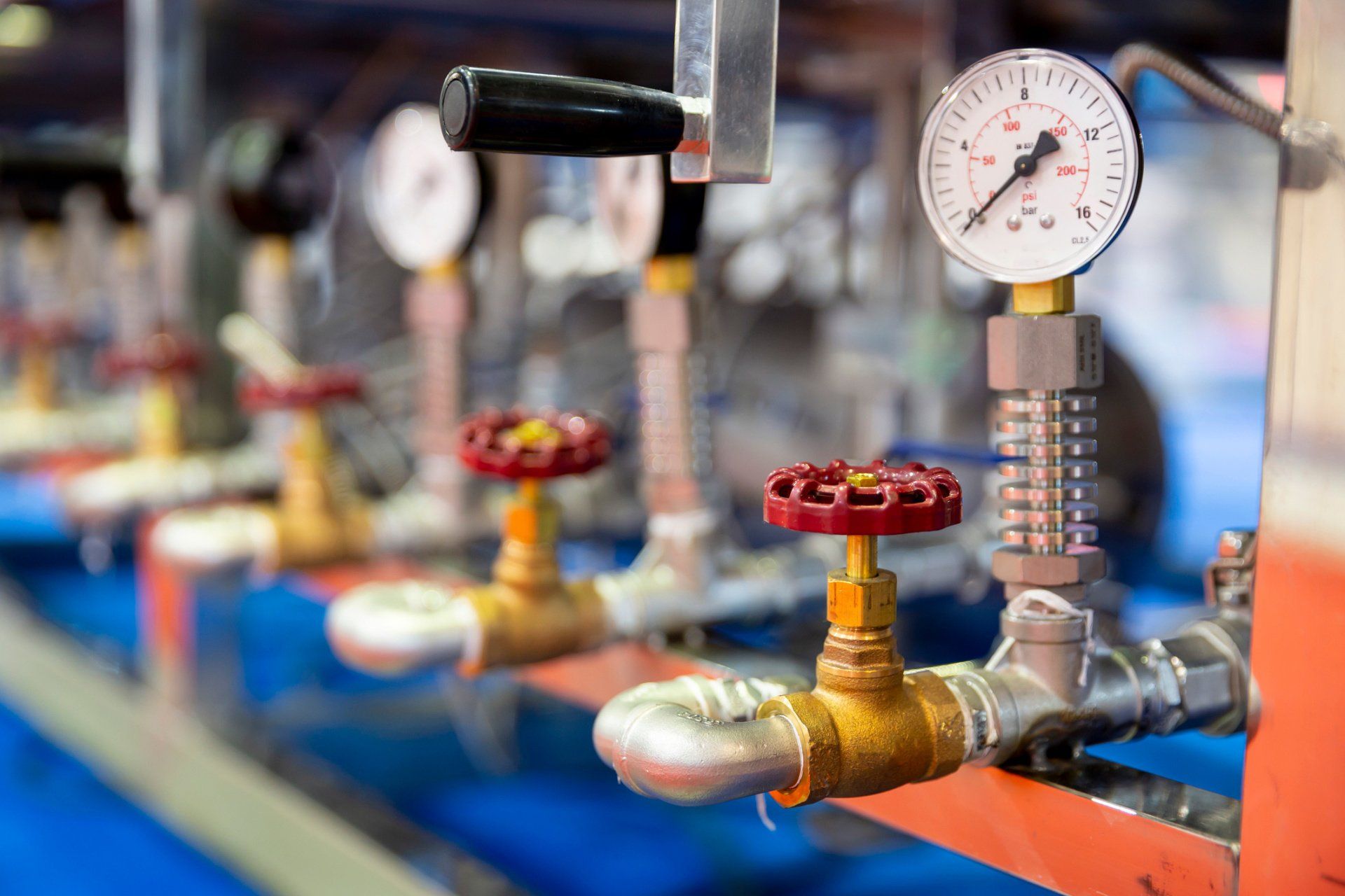
Cavitation is the rapid formation and implosion of air cavities in the hydraulic fluid. When these air cavities collapse under pressure, they generate a lot of heat. In fact, temperatures can reach up to 2700 degrees C at the point of implosion! Not only does cavitation compromise the lubrication properties of the oil, the excessive heat that is generated is extremely damaging to the hydraulic pump and the system as a whole. Attacking hoses and seals and causing metal components to expand and wear.
This happens when air makes its way into the system via air leaks at points like pump seals, and pipe fittings. And what happens next in a hydraulic system? Compression! Air generates heat when compressed, which naturally leads to an increase in temperature if left untreated. In extreme circumstances it can also lead to ‘hydraulic dieseling’ whereby compressed air bubbles actually explode in the same process that powers diesel engines. This is not good and leads to degradation of the fluid and damage to system components through loss of lubrication and burning of seals.
As pumps wear, the internal leakage or “slippage” increases. Essentially, fluid is able to make its way past tight fitting components, which reduces the efficiency of the pump, but in addition, as this occurs, fluid moves from a high pressure to a low pressure without doing any mechanical work, since according to the laws of physics energy cannot be destroyed, it is instead converted into heat.
A build-up of excessive heat is a symptom of hydraulic pump problems, but it is far from the only signal that there may be something wrong. There are other important warning signs that you should pay attention to. These include unusual noises, pressure problems and flow problems. Each of these symptoms provide clues about any potential pump problems that need to be addressed - so it’s important to familiarise yourself with all of these issues. To help, we’ve created a downloadable troubleshooting guide containing more information about each of these issues. So that you can keep your system up and running and avoid unplanned downtime. Download ithere.

Hydraulic pumps generate heat while they run. However, hydraulic fluid temperature should never exceed180 degreesF (82 degrees C) under normal working conditions. If your hydraulic pump temperature rises above this, then that is a sign that your pump is likely overheating. One of the most common causes of hydraulic system failure is a hydraulic pump that runs too hot or overheats.
When a hydraulic pump runs at a too-high temperature for too long, it can ultimately lead to pump failure. Once a hydraulic pump begins to fail, it can potentially damage the entire hydraulic system by sending contaminants and debris into the system that can damage its other components.
In addition, when some hydraulic fluids are subject to high temperatures, they can thin and lose their viscosity. When hydraulic fluid is too thin, it is much more likely to leak, and fluid that has lost its viscosity cannot lubricate your pump properly. Extremely hot fluid can also damage pump seals, further increasing the chance of a pump leak.
Some hydraulic fluids thicken and oxidize when exposed to high heat instead of thinning. When hydraulic fluids are too thick, they can restrict flow throughout the entire hydraulic system, which leads to your system heating up even further.
The sooner you determine why your hydraulic pump is running hot and repair the cause of the problem, the less likely your hydraulic system will develop irreversible damage or fail completely.
Hydraulic pumps overheat for many reasons. Just a few of the most common causes of hydraulic pump overheating include: Contaminated hydraulic fluid. When fluid has debris and dirt, contaminant particles can quickly build up on hydraulic system filters, leading to filter clogs. Your pump has to work harder to pump fluid through clogged filters, which leads to overheating.
Aeration. Air leaks at seals and fittings on your hydraulic system components can lead to air entering your system and forming bubbles in your fluid. Air bubbles generate heat when your system compresses them and then pass this heat into the surrounding fluid, overheating it.
Low reservoir fluid. Since your hydraulic system releases some of the heat it creates into reservoir fluid, a low reservoir fluid level can contribute to overheating.
Blocked or damaged heat exchanger. This component is also an important part of your hydraulic pump"s cooling system. If it is blocked or damaged, then it cannot help remove heat from your pump properly.
Once your hydraulic pump beings overheating, you need to find the cause of the problem and repair it. That way, your pump can begin operating within its ideal temperature range again.
If your pump overheats due to fluid contamination, then either remove all contaminants from existing fluid or remove the current contaminated fluid from the system and add fresh fluid. Be sure to filter all fresh hydraulic fluid before you add it to your system because even this fresh fluid can contain contaminants. Also, replace your fluid filters on a regular basis to prevent the overheating that can occur when these filters become blocked with debris.
If air has entered your system through leaky seals and fittings, then have a hydraulic system repair expert inspect and replace or tighten these fittings. Have a hydraulic system repair expert also look at heat exchanger damage to determine if the exchanger needs repairing or replacing.
Finally, be sure to check your system"s reservoir fluid level on a regular basis. Add new fluid when necessary to help this reservoir perform its important task of helping to keep your pump cool.
Your hydraulic pump should always operate within its ideal temperature range. If your pump is running hot, then contact the hydraulic pump experts at Quad Fluid Dynamics, Inc., forhydraulic pump diagnosis and repairtoday.

You can use multiple different upgrades and tuning methods on hydraulic systems. Many users will invest in upgrades that promise more flow and speed. The issue with these upgrades is that they"re not always fit for the hydraulic systems they"re applied to.
Since everything needs to stay in balance, you must make sure your upgrades match the entirety of your hydraulic system. For example, a higher flow pump can help give increased capabilities to a hydraulic system, but did you also check to see if the system"s hoses and piping can handle that increase in flow?
The increased flow can hit your smaller hoses hard and require more pressure just to get through them. This goes for any part of the hydraulic system that isn"t readily capable of handling more flow.
When you make upgrades, also ascertain if you need to change other components. In the example of the higher flow pump, you can simply increase your hose size, and that makes all the difference.

The experimental results show that 75% of the failure of hydraulic system of concrete pump truck (truck-mounted pump) is caused by pollution, overheating and air entry. If you understand some basic principles and understand the main factors leading to failure, you will ensure that the system is in good working condition for a long time. The details are as follows:
(1) The outside of the system is not clean. The unclean substance is brought into the system when refueling or inspecting the quantity of oil, or through the damaged oil seal or sealing ring.
(2) The internal cleaning is not thorough. Fine stone pumps use a number of concrete pumps technology, fine stone concrete conveying equipment. In the construction of fine stone concrete or mortar backfilling layer in geothermal engineering, the use of fine stone concrete pump is not easy to destroy the geothermal pipeline, and can greatly improve the construction efficiency and reduce the labor intensity of workers. There is still a small amount of dirt residue in the fuel tank or parts.
(6) Oil that has gradually deteriorated will corrode (meaning: rot, disappear, erode, etc.) parts. Corroded metals may become free molecules suspended in oil.
(1) When air or water enters the oil, when the hydraulic pump converts the oil into pressure oil, air and water will contribute to the increase of heat and cause overheating;
(5) If the return valve is not adjusted properly or the damaged parts are not replaced in time, sometimes heat will be generated. Mortar pump is a cantilever single-stage single-suction centrifugal pump. It is designed and developed for conveying corrosive medium containing fine particles. The pump is made of UHMW-PE with steel lining. This material is a new generation of corrosion-resistant and wear-resistant engineering plastics for pumps. Its outstanding advantage is that it has excellent wear resistance and impact resistance (especially in all plastics). Low temperature impact resistance, creep resistance (environmental stress cracking resistance) and excellent corrosion resistance.
(3) Oil suction pipelines are worn, scratched or corroded (meaning: decay, disappearance, erosion, etc.), so air enters. Small concrete pump (pump truck) consists of pump body and conveying pipe. It is a kind of machine that uses pressure to continuously convey concrete along pipeline. It is mainly used in building, bridge and tunnel construction. It is mainly divided into gate valve concrete pump and S valve concrete pump. Another is to install the pump body on the chassis of the car, and then equipped with a retractable or flexible cloth bar, and constitute the pump truck.

Hyundai hydraulic pumps are integral parts of excavators. The company is the third largest manufacturer in the world. As one of the leading brands, Hyundai has been popularized after producing high quality and durable products over time.
An excavator Hyundai hydraulic pump can overheat for a variety of reasons. The most common cause is actually running the pump at too low of an RPM. When the pump is not turning fast enough, it can’t move the oil through the system quickly enough and it starts to overheat. Another common cause is a blockage in the system somewhere. This could be a blockage in the suction line, return line, or even in the pump itself. If there is a blockage, the oil can’t flow properly and it will start to overheat.
If your excavator Hyundai hydraulic pump is overheating, there are a few things you can do to try and fix the problem. First, check the RPM of the pump. If it is running too low, increase it until it is running at the proper speed. Next, check for any blockages in the system. If you find one, clean it out and see if that fixes the problem. Finally, if neither of those two things works, you may need to replace the pump itself.
There are many potential causes of an excavator Hyundai hydraulic pump overheating. The most common cause is a loss of hydraulic fluid due to a leak in the system. Other causes can include a build-up of dirt and debris in the system, or a problem with the pump itself.
If you suspect that your excavator’s hydraulic pump is overheating, the first step is to check for leaks. If you find a leak, make sure to repair it as soon as possible. If there is no leak, then you will need to clean out the system to remove any dirt or debris that may be causing the problem.
If you are still having problems with your excavator’s hydraulic pump overheating, it may be necessary to replace the pump itself. This is a more complex repair, so it is best to consult with a qualified mechanic or dealer before proceeding.
There are several potential causes of an excavator Hyundai hydraulic pump overheating, but the most common cause is simply because the pump isn’t getting enough oil. This can happen for a variety of reasons, such as a leaking oil line or an incorrect amount of oil being used. Another potential cause is that the pump isn’t getting enough cooling water, which can be caused by a clogged water filter or an insufficient water supply. Whatever the cause, it’s important to get the problem fixed as soon as possible to avoid damage to the pump.
The Hyundai hydraulic pump is located in the engine bay of the excavator. It is responsible for providing hydraulic pressure to the excavator’s hydraulic system. If the pump overheats, it can cause damage to the hydraulic system and potentially lead to a loss of excavator performance. There are a few things that you can do to prevent the pump from overheating:
– Inspect the pump regularly for any potential leaks. Leaks can cause the fluid level to drop and also allow air to enter the system, which can cause problems.
If you’re noticing that the Hyundai hydraulic pump on your excavator is overheating, there are a few things you can do to prevent it. First, make sure that the pump is getting enough oil. If the pump isn’t properly lubricated, it will overheat. You should also check the cooling system to make sure it’s working properly. If the pump is still overheating, you may need to replace the seals or bearings.
If you have an excavator Hyundai, you may have experienced your hydraulic pump overheating. This can be a major problem, as it can lead to damaged equipment and even injuries. However, there are a few things you can do to help prevent this from happening. make sure that your excavator is properly ventilated. Second, check the fluid levels in your hydraulic system regularly. Third, use aHydraulic Pump Overheating Prevention Kit. By following these simple tips, you can help ensure that your hydraulic pump doesn’t overheat and cause damage to your equipment or yourself.

Overheating isa frequent problemwithin hydraulic systems that may be determined by specific components. Thisinternal problem lies within the pump and causes a hydraulic system to overheat in the following ways:
Contaminated hydraulic fluid is a common cause for a Hydraulic system to overheat. This can occur when the container is not sealed properly which causes dust, dirt,debris,or moisture to contaminate the fluid.With hydraulic systems running at higher pressures and more efficiently than ever before, it is important tomonitorthe cleanliness of one’s hydraulic fluid. Reducing contamination can decrease damage andwillallowoneto get the most out oftheirequipment.
Wrong valve calibration could resultin pressure difficulties which can cause a hydraulic system to overheat. The main cause of this is when a facility’s plant design changes and maintenance recalibrate the pressure relief valves for the updated operating pressure. If maintenance adjusts the pressure,and it stilldoes notsolve the problem, the pressure relief valve may have to be replaced entirely. Erosion to a valve is a common occurrence as dirt and debris settle and collectthroughout time. Maintaining the correct pressure will help your system keep up with production and not slow down.
Aeration in a hydraulic system can bea common issueand is caused by an outside air leak in the suction line.The pressure used in the suction line of hydraulic systems is below atmospheric pressure, so oilcannotleak out, but air can leak in.This will occur when there are loose, leaky seals and fittings which will allowtheair to seep in.Aeration can have severalnegative effectson top of overheatingsuch as increasedpump cavitation, excessive noise, and loss of horsepower.Some symptoms of Aeration may include foaming of the fluid, irregular movements, and banging and or loud clicking noises as the hydraulic system compresses and decompresses.
A blocked heat exchanger is significant toheating one’s hydraulic system, while cooling it down is just as important.Aninfrared thermometer isan effective wayto checkthe temperatureof a heat exchanger. Theadjustments can be made according tothedesign of theflow rateof oil.Make sure to replace the fluid fitterslocatedin the pumpon a regular basis to ensure theywill not get blocked andoverheat.
Oil Type plays a critical role inany hydraulic system. The wrong oil will not only affect the performance of the system but also cut down the lifespan of the machine. Theoil Viscositydeterminesthe maximum and minimum temperatures in which a hydraulic system can safelyoperate.Thin oils have a lowviscosity andflow more easily at low temperaturesthanthicker oils that have a higherviscosity.If the oil is too thin it can cause internal friction whichcreates heat and cancausethe system to overheat.
Low reservoir fluid is a common cause ofoverheating in hydraulic systems as itreleasesbuilt-upheatfrom the machineintothe fluid. Not having enough reservoir fluid cancontribute tocavitation andultimate damage to the pump.
Hydraulic pump failure candamage the entire hydraulic system.When a pump fails,debris, dirt, and grime kick out downstreamand can affect theoil,filter,valves, fluid, and actuator.Contactour KICK@$$ hydraulic system repair professionalsat Allied Hydraulic to avoid these problems.

Overheating ranks No. 2 in the list of most common problems with hydraulic equipment. Unlike leaks, which rank No. 1, the causes of overheating and its remedies are often not well understood by maintenance personnel
Heating of hydraulic fluid in operation is caused by inefficiencies. Inefficiencies result in losses of input power, which are converted to heat. A hydraulic system’s heat load is equal to the total power lost (PL) through inefficiencies and can be expressed as:
If the total input power lost to heat is greater than the heat dissipated, the hydraulic system will eventually overheat. Installed cooling capacity typically ranges between 25 and 40 percent of input power, depending on the type of hydraulic system.
How hot is too hot? Hydraulic fluid temperatures above 180°F (82°C) damage most seal compounds and accelerate degradation of the oil. While the operation of any hydraulic system at temperatures above 180°F should be avoided, fluid temperature is too high when viscosity falls below the optimum value for the hydraulic system’s components. This can occur well below 180°F, depending on the fluid’s viscosity grade.
To achieve stable fluid temperature, a hydraulic system’s capacity to dissipate heat must exceed its heat load. For example, a system with continuous input power of 100 kW and an efficiency of 80 percent needs to be capable of dissipating a heat load of at least 20 kW. Assuming this system has a designed cooling capacity of 25 kW, anything that increases heat load above 25 kW or reduces the cooling system’s capacity below 25 kW will cause the system to overheat.
Consider this example. I was recently asked to investigate and solve an overheating problem in a mobile application. The hydraulic system was comprised of a diesel-hydraulic power unit, which was being used to power a pipe-cutting saw. The saw was designed for sub-sea use and was connected to the hydraulic power unit on the surface via a 710-foot umbilical. The operating requirements for the saw were 24 GPM at 3,000 PSI.
The hydraulic power unit had a continuous power rating of 37 kW and was fitted with an air-blast heat exchanger. The exchanger was capable of dissipating 10 kW of heat under ambient conditions or 27 percent of available input power (10/37 x 100 = 27). The performance of all cooling circuit components were checked and found to be operating within design limits.
At this point it, was clear that the overheating problem was being caused by excessive heat load. Concerned about the length of the umbilical, I calculated its pressure drop. The theoretical pressure drop across 710 feet of ¾-inch pressure hose at 24 GPM is 800 PSI. The pressure drop across the same length of 1-inch return hose is 200 PSI. The theoretical heat load produced by the pressure drop across the umbilical of 1,000 PSI (800 + 200 = 1,000) was 10.35 kW. This meant that the heat load of the umbilical was 0.35 kW more than the heat dissipation capacity of the hydraulic system’s heat exchanger. This, when combined with the system’s normal heat load (inefficiencies) was causing the hydraulic system to overheat.
Hydraulic systems dissipate heat through the reservoir. Therefore, check the reservoir fluid level and if low, fill to the correct level. Check that there are no obstructions to airflow around the reservoir, such as a buildup of dirt or debris.
Inspect the heat exchanger and ensure that the core is not blocked. The ability of the heat exchanger to dissipate heat is dependent on the flow-rate and temperature of both the hydraulic fluid and the cooling air or water circulating through the exchanger. Check the performance of all cooling circuit components and replace as necessary.
An infrared thermometer can be used to check the performance of a heat exchanger, provided the design flow-rate of hydraulic fluid through the exchanger is known. To do this, measure the temperature of the oil entering and exiting the exchanger and substitute the values in the following formula:
For example, if the measured temperature drop across the exchanger is 4ºC and the design oil flow-rate is 90 L/min, the exchanger is dissipating 10 kW of heat. Relating this to a system with a continuous input power of 100 kW, the exchanger is dissipating 10 percent of input power. If the system is overheating, it means that either there is a problem in the cooling circuit or the capacity of the exchanger is insufficient for the ambient operating conditions.
On the other hand, if the measured temperature drop across the exchanger is 10ºC and the design oil flow-rate is 90 L/min, the exchanger is dissipating 26 kW of heat. Relating this to a system with a continuous input power of 100 kW, the exchanger is dissipating 26 percent of input power. If the system is overheating, this means that the efficiency of the system has fallen below 74 percent.
Where there is a pressure drop, heat is generated. This means that any component in the system that has abnormal, internal leakage will increase the heat load on the system and can cause the system to overheat. This could be anything from a cylinder that is leaking high-pressure fluid past its piston seal, to an incorrectly adjusted relief valve. Identify and change-out any heat-generating components.
A common cause of heat generation in closed center circuits is the setting of relief valves below, or too close to, the pressure setting of the variable-displacement pump’s pressure compensator. This prevents system pressure from reaching the setting of the pressure compensator. Instead of pump displacement reducing to zero, the pump continues to produce flow, which passes over the relief valve, generating heat. To prevent this problem in closed center circuits, the pressure setting of the relief valve(s) should be 250 PSI above the pressure setting of the pump’s pressure compensator (Figure 1).
Continuing to operate a hydraulic system when the fluid is over-temperature is similar to operating an internal combustion engine with high coolant temperature. Damage is guaranteed. Therefore, whenever a hydraulic system starts to overheat, shut it down, identify the cause and fix it.

Every OEM says it wants quality, but the reality is that machine builders can choose from countless hydraulic components that vary widely in performance and price—from cheap, “throw-away” parts to high-quality and, more-expensive, products that are built to last.
How does an engineer sort out the various offerings? Here’s a look at one fluid-power manufacturer’s unique philosophy on making a well-crafted pump, thanks to a keen understanding of how poorly built pumps fail.
Most pump designers begin with theoretical concepts of fluid power and mechanical engineering to create a product that should suit the customer’s needs. Hydraulics manufacturer Permco Inc., based in Streetsboro, Ohio, has taken a different tack on the route to building high-quality parts.
Permco’s roots began in the early 20th century as a small shop servicing Appalachian mining equipment. “Unlike most traditional manufacturers, we got our start in this industry on the repair side. We had the chance to start at the opposite end of the learning curve—with failures—and looked at all the things that could possibly go wrong,” said Robby Shell, the company’s chief operating officer.
It’s hard to imagine worse operating conditions for hydraulics than in underground coal mines, he explained. Mechanics routinely dealt with units with internal parts burned due to overheating, seized from lack of lubrication, fouled with contaminants or damaged due to overpressure conditions. They also learned firsthand a sense of urgency to make a repair right the first time and get machines up and running quickly, as the cost of unexpected breakdowns can run into the tens of thousands of dollars an hour.
“So from that rebuild failure analysis experience, we got to see what impact engineering design, manufacturing processes and quality control, as well as operating conditions and servicing, played on the overall performance and life of components,” Shell continued.
“Take our gear pumps. We looked at many designs and the best gear design, based on our experience in differentials and transmissions for these applications, has a gear tooth that is shaped vertically, and then shaved after the shaping process,” he said.
Why? Well, cutting a gear tooth vertically produces little tiny cut marks, he indicated. Left as is, those imperfections would grind against each other, generate noise and wear debris, and hurt efficiency. A post-machining shaving process, however, removes the marks and smooths the face for quiet operations, and it also ensures parallel contact between the housing and gear profile.
In contrast, virtually every other competitor cuts their gears on horizontal hobbing machines, said Shell. “Just by the nature of a hobbing tool, those gears will have a crowned profile from end to end. When new, the difference isn’t noticeable.” But over time, as the gears rotate against each other and the housing, a crowned gear creates leak paths. Pumps with vertically cut gears, in contrast, have a straighter tooth profile and wear more uniformly, and thus maintain efficiencies longer, he said. “We were gear cutters in the old days, and that background taught us to implement design features that enhance the operation of our pumps. The way we shape and shave our gears creates a better tooth profile.”
Some hydraulics manufacturers rely on their own foundries and pour their own housing castings. “Well, in the foundry world, technology is really, really expensive. Upgrades are very costly, so there is a natural reluctance against constantly investing in the newest systems,” noted Shell.
Companies like Permco aren’t boxed in. They have the luxury of choosing foundries that rely on the latest and best technology. Not only are there cosmetic differences between state-of-the-art castings versus older offerings. It also results in higher density and fewer porosity issues, which translate into better mechanical integrity and machinability.
Another differentiator among pump manufacturers, in Shell’s view, is that some make high-quality, well-engineered products, and others either don’t understand the basics or simply don’t care.
“For instance, some years ago Permco developed a game-changing thrust plate called a diverter plate,” he said. When subjected to system pressure, the gears in a pump tend to flex and move toward the low-pressure side. To compensate, company engineers developed thrust plates incorporating precision grooves that create a minute flow path to divert high-pressure fluid to the inlet side. In turn, that helps balance bearing loads.
When the patents expired some competitors copied the plates and, without understanding why the feature is there, went one step further and introduced a bi-rotational version—with flow paths in both directions for running a pump clockwise and counterclockwise. They surmised that if the diverter works in one direction, a design suited for both directions would be even better. In reality, the bi-ro design doesn’t work because it creates too many leak paths and efficiency drops severely. But unsophisticated pump builders don’t know that. “We see a lot of those types of issues. They don’t understand the nuances of what this groove really does. They know it has 14° a chamfer on it. Why 14° not 16°? They can’t tell you those things,” said Shell.
Not only do such differences matter in design and manufacturing, they hold for how pumps are assembled, too. Building a high-quality pump is meticulous work, stressed Shell. “Our people do prep work very similar to what you would see in a good engine rebuild shop.” For instance, they might take a honing stone or emery cloth and kiss a few areas on the gear before installation. That’s because when gears are pulled from a warehouse shelf and moved to the assembly station, it’s not unheard of to accidentally bump and nick a gear. If that gear gets assembled as is, and it subsequently rides on the soft bronze plate, the burr will cut a groove and create a leak path. Left unchecked, that pump will run inefficiently and underperform. Few manufacturers take such a hands-on approach to quality, emphasized Shell.
“But probably the biggest thing that differentiates us is we test every pump that goes out of this building. For peace of mind from the customer’s standpoint, that’s huge,” he stressed. Each pump gets assembled with new parts to create a tight package. Then it’s run up to 2,000 psi pressure, where the components flex and the gears will take a take a slight wipe—removing perhaps 0.0005 to 0.001 in. of material from the housing. That’s acceptable, notes Shell, because filters on the test benches trap the wear particles, instead of remaining behind to contaminate a customer’s hydraulic system.
Tests confirm leak-free and quiet operation and that flow meets design specs. And any problem gets flagged immediately, not at the customer’s site. It’s a significant undertaking. That’s why most other manufacturers only test 1 in 10 or 1 in 50 units, said Shell.
Finally, the approved product is assigned a serial number that includes the initials of the assembler—as a further sign of the workmanship that stands behind a high-quality pump.
“I guarantee you many other manufacturers don’t take the extra care we put into these units,” said Shell, and it shows when they test competing products. “Some of the dump-truck pumps coming in from offshore sources—mainly China—have failure rates upwards of 10 to 15%. Ours is less than one quarter of 1%.”
It’s due to a different mindset behind the way they build pumps, versus Permco’s philosophy, he emphasized. Some manufacturers feel units made to less-stringent standards are acceptable because often, they only see light duty. Take the case of a typical dump truck: the duty cycle for the hydraulics is often quite limited, he noted. Generally, a truck gets loaded, transports material to a site, and only then is the pump switched on—where it operates for perhaps a minute to raise, dump and lower the bed. And the cycle might get repeated perhaps a dozen times per day.
So, in theory, a dump pump designed and built to handle just light, intermittent duty should be more than adequate, he continued. But the world isn’t perfect—many things can and will go wrong, said Shell. For instance, the operator keeps the pump on too long and it overheats; or it runs low on oil; or the truck bed is overloaded, and a pump with no margin of safety is overtaxed and fails.
A well-engineered, high-quality pump can overcome many of these issues; lesser products can’t, he said. “We understand how offshore units are built and we can predict, generally speaking, how they will fail.” Almost all of these areas of weakness get addressed in Permco’s engineering, manufacturing, assembly and testing processes—steps that are missing in pumps coming from offshore sources. But those manufacturers justify an increased failure rate because their pump costs $50 less to make, said Shell.
“We saw the invasion of these offshore dump pumps a few years ago, and we had plenty of opportunity to make this same pump in China. So we had two choices in that market. Either join it, and it’s just a race to the bottom. Or offer something that differentiates us from the rest of the market.” That’s where the American Champ, Permco’s pumps like the Gemini series comes in, he explained.
The pumps are engineered and manufactured based on Permco’s years of experience, and assembled in the U.S. from globally sourced, world-class components. What’s interesting is that many of the pump components are made not only in the company’s Ohio plant, but in Permco’s manufacturing operation in Tianjin, China.
“There’s virtually zero difference between our China and U.S. products, and there’s a reason for that,” explained Shell. Instead of relying on subcontractors or joint ventures, 16 years ago the U.S. plant manager (now with 44 years of experience) moved to China to set up a gear manufacturing plant, with processes identical to those in the domestic plant. By installing the same types of machine tools, instituting the same procedures, and with in-depth training and constant supervision, the Chinese workers have come to understand how important quality really is.
“It’s all about a different way of thinking. Again, we came out of the mining component repair world. When a Joy mining machine breaks down and sits idle for 16 hours, and a rebuilt transmission gets carted six miles underground to make the repair, it is imperative that when power is switched on, the work was done right.” The focus is on getting the equipment up and running again, not on saving a few dollars on a pump that might fail in short order, or may not work at all.
Dump pumps, as the name indicates, are routinely used in hydraulic circuits for lifting and lowering dump truck and trailer beds. The basic design typically includes a pump section, a directional control valve and a relief valve incorporated into the pump as a complete package, with internal fluid connections to the components. They have been around for more than 50 years and are common throughout the industry.
A notable innovation is now shaking up that market. Permco has developed a unit that sets it apart from conventional dump pumps. The Gemini DG-20/RG-20 is designed for-dual use applications, thanks to a second set of relief valves and selector valves. That lets the Gemini not only control a dump bed, it can also control a walking (live) floor.
Walking floors are used on trailers that do not tip, like a dump trailer. Instead, slats on the movable floor transport and “walk” the load off the end. They’re frequently used in the refuse industry, in landscaping to handle mulch and wood chips, and in other areas where height restrictions would severely limit the capability to raise a dump bed.
Walking-floor trailers tend to operate at higher pressures than hydraulics in dump applications. Traditionally, that has meant a fleet operator with dump trucks requires separate tractors for walking floors. Now, thanks to the Gemini pump, an operator can run a dump truck, and then switch the same tractor to a trailer with a walking floor. Equipping the vehicle with a Gemini pump system lets the operator easily change pressure settings on demand, and eliminates the need for a dedicated rig that can easily cost $150,000.
Another notable engineering feature is that the Gemini also incorporates a load check feature into the valve design, letting the operator raise the bed and then hold the load in place—say when spreading asphalt. To enhance reliability, the design differs from conventional units in that it’s direct-acting.
Typical designs incorporate a load check into a pilot-operated relief valve. As a result, the tiny orifice pilot senses operating pressure before it activates, but the orifice can easily get plugged by contaminants and the valve fails. The Permco direct-acting relief valve eliminates orifice plugging issues.
The load check and relief are also self-cleaning. Because it mounts in the flow stream, and clearances are sufficiently large, contaminants are flushed away—so there are few occurrences where the relief valve can’t open or close and a bed drifts or hangs up. That, according to Permco officials, offers a distinct advantage over competing designs.
The Gemini is rated for 37 gpm at 1,800 gpm and runs at two pressures, low (2,000 psi) for dump bodies and high (typically 3,200 psi) for live floors. Operators can easily switch from low to high pressure using cab-mounted controls. The pump includes dowelled construction and is assembled in the U.S. and 100% factory tested. In addition to use on dump trailers and walking floors, the Gemini is also suitable for gooseneck transporters, dump trucks, crane-equipment vehicles, roll-off trucks and refuse collection
This website is using a security service to protect itself from online attacks. The action you just performed triggered the security solution. There are several actions that could trigger this block including submitting a certain word or phrase, a SQL command or malformed data.

This website is using a security service to protect itself from online attacks. The action you just performed triggered the security solution. There are several actions that could trigger this block including submitting a certain word or phrase, a SQL command or malformed data.

Our growth depends within the innovative equipment, fantastic talents and repeatedly strengthened technology forces for Factory made hot-sale China Group 4+3 Gear Pumps Hydraulic Pump Tandem Gear Pump, Teamwork is encouraged at all levels with regular campaigns. Our research crew experiments on various developments inside the industry for improvement in the merchandise.
Our growth depends within the innovative equipment, fantastic talents and repeatedly strengthened technology forces for China Gear Pump, China Hydraulic Pump, China Hydraulic Pump Single Gear Pump, Hydraulic Gear Pump, For many years, we now have adhered to the principle of customer oriented, quality based, excellence pursuing, mutual benefit sharing. We hope, with great sincerity and good will, to have the honor to help with your further market.

21683 hydraulic pump made in china products are offered for sale by suppliers on Alibaba.comAbout 5% % of these are construction machinery parts, 5%% are hydraulic pumps, and 2%% are pumps.
A wide variety of hydraulic pump made in china options are available to you, such as new, used.You can also choose from piston pump, gear pump and vane pump hydraulic pump made in china,as well as from 1 year, 6 months, and 1.5 years hydraulic pump made in china, and whether hydraulic pump made in china is hydraulic power units, fittings, or hydraulic motors.
Mechanical pumps serve in a wide range of applications such as pumping water from wells, aquarium filtering, pond filtering and aeration, in the car industry for water-cooling and fuel injection, in the energy industry for pumping oil and natural gas or for operating cooling towers and other components of heating, ventilation and air conditioning systems. In the medical industry, pumps are used for biochemical processes in developing and manufacturing medicine, and as artificial replacements for body parts, in particular the artificial heart and penile prosthesis.
When a pump contains two or more pump mechanisms with fluid being directed to flow through them in series, it is called a multi-stage pump. Terms such as two-stage or double-stage may be used to specifically describe the number of stages. A pump that does not fit this description is simply a single-stage pump in contrast.
In biology, many different types of chemical and biomechanical pumps have evolved; biomimicry is sometimes used in developing new types of mechanical pumps.
Pumps can be classified by their method of displacement into positive-displacement pumps, impulse pumps, velocity pumps, gravity pumps, steam pumps and valveless pumps. There are three basic types of pumps: positive-displacement, centrifugal and axial-flow pumps. In centrifugal pumps the direction of flow of the fluid changes by ninety degrees as it flows over an impeller, while in axial flow pumps the direction of flow is unchanged.
Some positive-displacement pumps use an expanding cavity on the suction side and a decreasing cavity on the discharge side. Liquid flows into the pump as the cavity on the suction side expands and the liquid flows out of the discharge as the cavity collapses. The volume is constant through each cycle of operation.
Positive-displacement pumps, unlike centrifugal, can theoretically produce the same flow at a given speed (rpm) no matter what the discharge pressure. Thus, positive-displacement pumps are constant flow machines. However, a slight increase in internal leakage as the pressure increases prevents a truly constant flow rate.
A positive-displacement pump must not operate against a closed valve on the discharge side of the pump, because it has no shutoff head like centrifugal pumps. A positive-displacement pump operating against a closed discharge valve continues to produce flow and the pressure in the discharge line increases until the line bursts, the pump is severely damaged, or both.
A relief or safety valve on the discharge side of the positive-displacement pump is therefore necessary. The relief valve can be internal or external. The pump manufacturer normally has the option to supply internal relief or safety valves. The internal valve is usually used only as a safety precaution. An external relief valve in the discharge line, with a return line back to the suction line or supply tank provides increased safety.
Rotary-type positive displacement: internal or external gear pump, screw pump, lobe pump, shuttle block, flexible vane or sliding vane, circumferential piston, flexible impeller, helical twisted roots (e.g. the Wendelkolben pump) or liquid-ring pumps
Drawbacks: The nature of the pump requires very close clearances between the rotating pump and the outer edge, making it rotate at a slow, steady speed. If rotary pumps are operated at high speeds, the fluids cause erosion, which eventually causes enlarged clearances that liquid can pass through, which reduces efficiency.
Hollow disk pumps (also known as eccentric disc pumps or Hollow rotary disc pumps), similar to scroll compressors, these have a cylindrical rotor encased in a circular housing. As the rotor orbits and rotates to some degree, it traps fluid between the rotor and the casing, drawing the fluid through the pump. It is used for highly viscous fluids like petroleum-derived products, and it can also support high pressures of up to 290 psi.
Vibratory pumps or vibration pumps are similar to linear compressors, having the same operating principle. They work by using a spring-loaded piston with an electromagnet connected to AC current through a diode. The spring-loaded piston is the only moving part, and it is placed in the center of the electromagnet. During the positive cycle of the AC current, the diode allows energy to pass through the electromagnet, generating a magnetic field that moves the piston backwards, compressing the spring, and generating suction. During the negative cycle of the AC current, the diode blocks current flow to the electromagnet, letting the spring uncompress, moving the piston forward, and pumping the fluid and generating pressure, like a reciprocating pump. Due to its low cost, it is widely used in inexpensive espresso machines. However, vibratory pumps cannot be operated for more than one minute, as they generate large amounts of heat. Linear compressors do not have this problem, as they can be cooled by the working fluid (which is often a refrigerant).
Reciprocating pumps move the fluid using one or more oscillating pistons, plungers, or membranes (diaphragms), while valves restrict fluid motion to the desired direction. In order for suction to take place, the pump must first pull the plunger in an outward motion to decrease pressure in the chamber. Once the plunger pushes back, it will increase the chamber pressure and the inward pressure of the plunger will then open the discharge valve and release the fluid into the delivery pipe at constant flow rate and increased pressure.
Pumps in this category range from simplex, with one cylinder, to in some cases quad (four) cylinders, or more. Many reciprocating-type pumps are duplex (two) or triplex (three) cylinder. They can be either single-acting with suction during one direction of piston motion and discharge on the other, or double-acting with suction and discharge in both directions. The pumps can be powered manually, by air or steam, or by a belt driven by an engine. This type of pump was used extensively in the 19th century—in the early days of steam propulsion—as boiler feed water pumps. Now reciprocating pumps typically pump highly viscous fluids like concrete and heavy oils, and serve in special applications that demand low flow rates against high resistance. Reciprocating hand pumps were widely used to pump water from wells. Common bicycle pumps and foot pumps for inflation use reciprocating action.
These positive-displacement pumps have an expanding cavity on the suction side and a decreasing cavity on the discharge side. Liquid flows into the pumps as the cavity on the suction side expands and the liquid flows out of the discharge as the cavity collapses. The volume is constant given each cycle of operation and the pump"s volumetric efficiency can be achieved through routine maintenance and inspection of its valves.
This is the simplest form of rotary positive-displacement pumps. It consists of two meshed gears that rotate in a closely fitted casing. The tooth spaces trap fluid and force it around the outer periphery. The fluid does not travel back on the meshed part, because the teeth mesh closely in the center. Gear pumps see wide use in car engine oil pumps and in various hydraulic power packs.
A screw pump is a more complicated type of rotary pump that uses two or three screws with opposing thread — e.g., one screw turns clockwise and the other counterclockwise. The screws are mounted on parallel shafts that have gears that mesh so the shafts turn together and everything stays in place. The screws turn on the shafts and drive fluid through the pump. As with other forms of rotary pumps, the clearance between moving parts and the pump"s casing is minimal.
Widely used for pumping difficult materials, such as sewage sludge contaminated with large particles, a progressing cavity pump consists of a helical rotor, about ten times as long as its width. This can be visualized as a central core of diameter x with, typically, a curved spiral wound around of thickness half x, though in reality it is manufactured in a single casting. This shaft fits inside a heavy-duty rubber sleeve, of wall thickness also typically x. As the shaft rotates, the rotor gradually forces fluid up the rubber sleeve. Such pumps can develop very high pressure at low volumes.
Named after the Roots brothers who invented it, this lobe pump displaces the fluid trapped between two long helical rotors, each fitted into the other when perpendicular at 90°, rotating inside a triangular shaped sealing line configuration, both at the point of suction and at the point of discharge. This design produces a continuous flow with equal volume and no vortex. It can work at low pulsation rates, and offers gentle performance that some applications require.
A peristaltic pump is a type of positive-displacement pump. It contains fluid within a flexible tube fitted inside a circular pump casing (though linear peristaltic pumps have been made). A number of rollers, shoes, or wipers attached to a rotor compresses the flexible tube. As the rotor turns, the part of the tube under compression closes (or occludes), forcing the fluid through the tube. Additionally, when the tube opens to its natural state after the passing of the cam it draws (restitution) fluid into the pump. This process is called peristalsis and is used in many biological systems such as the gastrointestinal tract.
These consist of a cylinder with a reciprocating plunger. The suction and discharge valves are mounted in the head of the cylinder. In the suction stroke, the plunger retracts and the suction valves open causing suction of fluid into the cylinder. In the forward stroke, the plunger pushes the liquid out of the discharge valve.
Efficiency and common problems: With only one cylinder in plunger pumps, the fluid flow varies between maximum flow when the plunger moves through the middle positions, and zero flow when the plunger is at the end positions. A lot of energy is wasted when the fluid is accelerated in the piping system. Vibration and
Triplex plunger pumps use three plungers, which reduces the pulsation of single reciprocating plunger pumps. Adding a pulsation dampener on the pump outlet can further smooth the pump ripple, or ripple graph of a pump transducer. The dynamic relationship of the high-pressure fluid and plunger generally requires high-quality plunger seals. Plunger pumps with a larger number of plungers have the benefit of increased flow, or smoother flow without a pulsation damper. The increase in moving parts and crankshaft load is one drawback.
Car washes often use these triplex-style plunger pumps (perhaps without pulsation dampers). In 1968, William Bruggeman reduced the size of the triplex pump and increased the lifespan so that car washes could use equipment with smaller footprints. Durable high-pressure seals, low-pressure seals and oil seals, hardened crankshafts, hardened connecting rods, thick ceramic plungers and heavier duty ball and roller bearings improve reliability in triplex pumps. Triplex pumps now are in a myriad of markets across the world.
Triplex pumps with shorter lifetimes are commonplace to the home user. A person who uses a home pressure washer for 10 hours a year may be satisfied with a pump that lasts 100 hours between rebuilds. Industrial-grade or continuous duty triplex pumps on the other end of the quality spectrum may run for as much as 2,080 hours a year.
The oil and gas drilling industry uses massive semi trailer-transported triplex pumps called mud pumps to pump drilling mud, which cools the drill bit and carries the cuttings back to the surface.
One modern application of positive-displacement pumps is compressed-air-powered double-diaphragm pumps. Run on compressed air, these pumps are intrinsically safe by design, although all manufacturers offer ATEX certified models to comply with industry regulation. These pumps are relatively inexpensive and can perform a wide variety of duties, from pumping water out of bunds to pumping hydrochloric acid from secure storage (dependent on how the pump is manufactured – elastomers / body construction). These double-diaphragm pumps can handle viscous fluids and abrasive materials with a gentle pumping process ideal for transporting shear-sensitive media.
Devised in China as chain pumps over 1000 years ago, these pumps can be made from very simple materials: A rope, a wheel and a pipe are sufficient to make a simple rope pump. Rope pump efficiency has been studied by grassroots organizations and the techniques for making and running them have been continuously improved.
Impulse pumps use pressure created by gas (usually air). In some impulse pumps the gas trapped in the liquid (usually water), is released and accumulated somewhere in the pump, creating a pressure that can push part of the liquid upwards.
Instead of a gas accumulation and releasing cycle, the pressure can be created by burning of hydrocarbons. Such combustion driven pumps directly transmit the impulse from a combustion event through the actuation membrane to the pump fluid. In order to allow this direct transmission, the pump needs to be almost entirely made of an elastomer (e.g. silicone rubber). Hence, the combustion causes the membrane to expand and thereby pumps the fluid out of the adjacent pumping chamber. The first combustion-driven soft pump was developed by ETH Zurich.
It takes in water at relatively low pressure and high flow-rate and outputs water at a higher hydraulic-head and lower flow-rate. The device uses the water hammer effect to develop pressure that lifts a portion of the input water that powers the pump to a point higher than where the water started.
The hydraulic ram is sometimes used in remote areas, where there is both a source of low-head hydropower, and a need for pumping water to a destination higher in elevation than the source. In this situation, the ram is often useful, since it requires no outside source of power other than the kinetic energy of flowing water.
Rotodynamic pumps (or dynamic pumps) are a type of velocity pump in which kinetic energy is added to the fluid by increasing the flow velocity. This increase in energy is converted to a gain in potential energy (pressure) when the velocity is reduced prior to or as the flow exits the pump into the discharge pipe. This conversion of kinetic energy to pressure is explained by the
A practical difference between dynamic and positive-displacement pumps is how they operate under closed valve conditions. Positive-displacement pumps physically displace fluid, so closing a valve downstream of a positive-displacement pump produces a continual pressure build up that can cause mechanical failure of pipeline or pump. Dynamic pumps differ in that they can be safely operated under closed valve conditions (for short periods of time).
Such a pump is also referred to as a centrifugal pump. The fluid enters along the axis or center, is accelerated by the impeller and exits at right angles to the shaft (radially); an example is the centrifugal fan, which is commonly used to implement a vacuum cleaner. Another type of radial-flow pump is a vortex pump. The liquid in them moves in tangential direction around the working wheel. The conversion from the mechanical energy of motor into the potential energy of flow comes by means of multiple whirls, which are excited by the impeller in the working channel of the pump. Generally, a radial-flow pump operates at higher pressures and lower flow rates than an axial- or a mixed-flow pump.
These are also referred to as All fluid pumps. The fluid is pushed outward or inward to move fluid axially. They operate at much lower pressures and higher flow rates than radial-flow (centrifugal) pumps. Axial-flow pumps cannot be run up to speed without special precaution. If at a low flow rate, the total head rise and high torque associated with this pipe would mean that the starting torque would have to become a function of acceleration for the whole mass of liquid in the pipe system. If there is a large amount of fluid in the system, accelerate the pump slowly.
Mixed-flow pumps function as a compromise between radial and axial-flow pumps. The fluid experiences both radial acceleration and lift and exits the impeller somewhere between 0 and 90 degrees from the axial direction. As a consequence mixed-flow pumps operate at higher pressures than axial-flow pumps while delivering higher discharges than radial-flow pumps. The exit angle of the flow dictates the pressure head-discharge characteristic in relation to radial and mixed-flow.
Regenerative turbine pump rotor and housing, 1⁄3 horsepower (0.25 kW). 85 millimetres (3.3 in) diameter impeller rotates counter-clockwise. Left: inlet, right: outlet. .4 millimetres (0.016 in) thick vanes on 4 millimetres (0.16 in) centers
Also known as drag, friction, peripheral, traction, turbulence, or vortex pumps, regenerative turbine pumps are class of rotodynamic pump that operates at high head pressures, typically 4–20 bars (4.1–20.4 kgf/cm2; 58–290 psi).
The pump has an impeller with a number of vanes or paddles which spins in a cavity. The suction port and pressure ports are located at the perimeter of the cavity and are isolated by a barrier called a stripper, which allows only the tip channel (fluid between the blades) to recirculate, and forces any fluid in the side channel (fluid in the cavity outside of the blades) through the pressure port. In a regenerative turbine pump, as fluid spirals repeatedly from a vane into the side channel and back to the next vane, kinetic energy is imparted to the periphery,
As regenerative turbine pumps cannot become vapor locked, they are commonly applied to volatile, hot, or cryogenic fluid transport. However, as tolerances are typically tight, they are vulnerable to solids or particles causing jamming or rapid wear. Efficiency is typically low, and pressure and power consumption typically decrease with flow. Additionally, pumping direction can be reversed by reversing direction of spin.
Steam pumps have been for a long time mainly of historical interest. They include any type of pump powered by a steam engine and also pistonless pumps such as Thomas Savery"s or the Pulsometer steam pump.
Recently there has been a resurgence of interest in low power solar steam pumps for use in smallholder irrigation in developing countries. Previously small steam engines have not been viable because of escalating inefficiencies as vapour engines decrease in size. However the use of modern engineering materials coupled with alternative engine configurations has meant that these types of system are now a cost-effective opportunity.
Valveless pumping assists in fluid transport in various biomedical and engineering systems. In a valveless pumping system, no valves (or physical occlusions) are present to regulate the flow direction. The fluid pumping efficiency of a valveless system, however, is not necessarily lower than that having valves. In fact, many fluid-dynamical systems in nature and engineering more or less rely upon valveless pumping to transport the working fluids therein. For instance, blood circulation in the cardiovascular system is maintained to some extent even when the heart"s valves fail. Meanwhile, the embryonic vertebrate heart begins pumping blood long before the development of discernible chambers and valves. Similar to blood circulation in one direction, bird respiratory systems pump air in one direction in rigid lungs, but without any physiological valve. In microfluidics, valveless impedance pumps have been fabricated, and are expected to be particularly suitable for handling sensitive biofluids. Ink jet printers operating on the piezoelectric transducer principle also use valveless pumping. The pump chamber is emptied through the printing jet due to reduced flow impedance in that direction and refilled by capillary action.
Examining pump repair records and mean time between failures (MTBF) is of great importance to responsible and conscientious pump users. In view of that fact, the preface to the 2006 Pump User"s Handbook alludes to "pump failure" statistics. For the sake of convenience, these failure statistics often are translated into MTBF (in this case, installed life before failure).
In early 2005, Gordon Buck, John Crane Inc.’s chief engineer for field operations in Baton Rouge, Louisiana, examined the repair records for a number of refinery and chemical plants to obtain meaningful reliability data for centrifugal pumps. A total of 15 operating plants having nearly 15,000 pumps were included in the su


 8613371530291