
why is my hydraulic pump overheating quotation

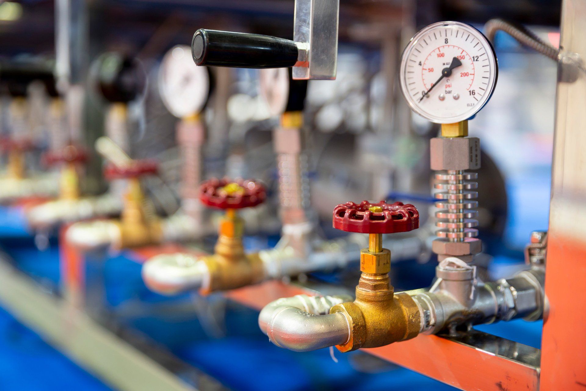
Hydraulic pumps generate heat while they run. However, hydraulic fluid temperature should never exceed180 degreesF (82 degrees C) under normal working conditions. If your hydraulic pump temperature rises above this, then that is a sign that your pump is likely overheating. One of the most common causes of hydraulic system failure is a hydraulic pump that runs too hot or overheats.
When a hydraulic pump runs at a too-high temperature for too long, it can ultimately lead to pump failure. Once a hydraulic pump begins to fail, it can potentially damage the entire hydraulic system by sending contaminants and debris into the system that can damage its other components.
In addition, when some hydraulic fluids are subject to high temperatures, they can thin and lose their viscosity. When hydraulic fluid is too thin, it is much more likely to leak, and fluid that has lost its viscosity cannot lubricate your pump properly. Extremely hot fluid can also damage pump seals, further increasing the chance of a pump leak.
Some hydraulic fluids thicken and oxidize when exposed to high heat instead of thinning. When hydraulic fluids are too thick, they can restrict flow throughout the entire hydraulic system, which leads to your system heating up even further.
The sooner you determine why your hydraulic pump is running hot and repair the cause of the problem, the less likely your hydraulic system will develop irreversible damage or fail completely.
Hydraulic pumps overheat for many reasons. Just a few of the most common causes of hydraulic pump overheating include: Contaminated hydraulic fluid. When fluid has debris and dirt, contaminant particles can quickly build up on hydraulic system filters, leading to filter clogs. Your pump has to work harder to pump fluid through clogged filters, which leads to overheating.
Aeration. Air leaks at seals and fittings on your hydraulic system components can lead to air entering your system and forming bubbles in your fluid. Air bubbles generate heat when your system compresses them and then pass this heat into the surrounding fluid, overheating it.
Low reservoir fluid. Since your hydraulic system releases some of the heat it creates into reservoir fluid, a low reservoir fluid level can contribute to overheating.
Blocked or damaged heat exchanger. This component is also an important part of your hydraulic pump"s cooling system. If it is blocked or damaged, then it cannot help remove heat from your pump properly.
Once your hydraulic pump beings overheating, you need to find the cause of the problem and repair it. That way, your pump can begin operating within its ideal temperature range again.
If your pump overheats due to fluid contamination, then either remove all contaminants from existing fluid or remove the current contaminated fluid from the system and add fresh fluid. Be sure to filter all fresh hydraulic fluid before you add it to your system because even this fresh fluid can contain contaminants. Also, replace your fluid filters on a regular basis to prevent the overheating that can occur when these filters become blocked with debris.
If air has entered your system through leaky seals and fittings, then have a hydraulic system repair expert inspect and replace or tighten these fittings. Have a hydraulic system repair expert also look at heat exchanger damage to determine if the exchanger needs repairing or replacing.
Finally, be sure to check your system"s reservoir fluid level on a regular basis. Add new fluid when necessary to help this reservoir perform its important task of helping to keep your pump cool.
Your hydraulic pump should always operate within its ideal temperature range. If your pump is running hot, then contact the hydraulic pump experts at Quad Fluid Dynamics, Inc., forhydraulic pump diagnosis and repairtoday.

Hot hydraulic fluid can be one of the causes of an overheating final drive motor. If your hydraulic fluid is running at a higher than normal temperature then it can cause problems for your entire hydraulic system. In this Shop Talk Blog post, we are going to talk about what can cause hydraulic fluid to overheat.
Another potential source of problems is a relief valve. If a relief valve fails or is out of adjustment, it can affect the system pressure. Changes in system pressure, as we just discussed, can also affect the temperature of the hydraulic fluid.
If you use the wrong type of hydraulic fluid for your machine, that, too, can cause the fluid to overheat. If that’s the case, then you need to replace the hydraulic fluid to fully address the problem.
If the oil cooler gets dirty or becomes plugged, that can also cause hydraulic fluid to run too hot. The solution to this problem is to take some time to clean off the oil cooler fins. Another potential source of problems is the cooling fan. If it is damaged, or if the fan belt isn’t at a right tension, then it can be the source of hot hydraulic fluid.
Another source of overheating lies in the level of your hydraulic fluid. If your reservoir is low on hydraulic fluid, that can cause the fluid that is in the system to overheat. However, that points to another problem: a leak somewhere. Don’t just top off the hydraulic fluid level, but also check for leaks that could be responsible for a low level of fluid.
If your hydraulic system is running too hot, then you need to track down the source of the problem. Hot hydraulic fluid will lead to damage and is a sign that something is wrong and needs to be addressed. If left unaddressed, then expensive issues and unnecessary downtime are bound to be the results.
is your partner in providing new or remanufactured final drive hydraulic motors from a single mini-excavator to a fleet of heavy equipment. Call today so we can find the right final drive or hydraulic component for you, or check out our online store to.
Whether you have a welded rod cylinder or telescopic cylinder, chances are you already know how destructive cylinder issues like fluid leaks can be. While leaks are known to cause cylinder issues, system overheating can be less obvious but just as pervasive. Hydraulic system overheating problems can be caused by different factors, including high heat hydraulic oil temperatures as well as system design pressure issues.
Hydraulic system heat contamination issues can be caused by different factors. With heat loading issues occurring from different sources, it is important to determine the correct cause of overheating for your hydraulic system. Common causes of hydraulic system overheating include:
Hydraulic fluid temperatures should stay within operating norms. Elevated or hot hydraulic oil can increase the chance of a system breakdown. High heat on hydraulic oil can increase oxidation, decreasing the oil’s performance and ability to maintain proper temperatures.
Higher hydraulic fluid temperatures can also create low viscosity issues. Maintaining normal viscosity levels allows your hydraulic system to function without added concerns about pump and valve wear and damage due to low viscosity.
Lack of fluid flow throughout your hydraulic system can cause motor issues as well as pump malfunctions and failure. Damage to your motor or pumps can require repair or component replacement.
Pressure issues can cause lack of fluid flow through your system. Pressure drop can occur due to lack of fluid flow through your system, resulting in higher operating temperatures and overheating.
While system damage from heat load can occur at any time, there are ways you can reduce and minimize system overheating. Troubleshooting tips for preventing hydraulic system overheating include:
Need performance-built replacement hydraulic cylinders or components? HCI stocks a wide inventory of high-performance hydraulic cylinders and component parts. We also design custom hydraulic cylinders manufactured with American-made machined parts. Contact us to discuss your hydraulic requirements with us today.

Is your hydraulic pump getting excessively hot during normal operation? Pumps do generate heat when running, however they are designed with specific heat parameters in mind. Overheating is an abnormal condition that leads to destructive issues such as thinning of hydraulic fluid, which leads to reduced lubrication, metal-on-metal contact of moving parts. And accelerated pump wear and failure.
Therefore it is never a good idea to ignore a pump that is exceeding its heat parameters under normal load. There are a number of factors that contribute to an excess buildup of heat and in this article, we’ll explain some of these issues.
Hydraulic fluid viscosity refers to the thickness or “resistance to pouring” of your hydraulic fluid. This is very important to the correct operation of your pump. The fluid not only transmits the power that moves your drives and actuators. It also lubricates internal components and removes heat from the system. Hydraulic fluid is designed to operate at a specific temperature range. As it heats, it becomes thinner and eventually it will lose the ability to lubricate moving parts. The increased friction may cause the pump to heat up, and naturally increased wear will be taking place when this is happening. On the other hand, hydraulic fluid that is too thick flows less efficiently within the system, which also results in heat buildup.
Fluid that is contaminated with dirt, debris, water and other impurities may cause heat build up in a few ways. Blocked fluid filters, pipes and strainers place undue load on the pump or even lead to pressure drops on the back side of filters that cause cavitation.
Low fluid levels can result in a condition in which not enough flow is reaching the critical hydraulic components and moving parts. This is known as oil starvation and just like running your car without oil, it will increase metal-on-metal friction and lead to increased heat and wear. Oil starvation can also be caused by clogged hydraulic filters, incorrect fluid reservoir design.
Cavitation is the rapid formation and implosion of air cavities in the hydraulic fluid. When these air cavities collapse under pressure, they generate a lot of heat. In fact, temperatures can reach up to 2700 degrees C at the point of implosion! Not only does cavitation compromise the lubrication properties of the oil, the excessive heat that is generated is extremely damaging to the hydraulic pump and the system as a whole. Attacking hoses and seals and causing metal components to expand and wear.
This happens when air makes its way into the system via air leaks at points like pump seals, and pipe fittings. And what happens next in a hydraulic system? Compression! Air generates heat when compressed, which naturally leads to an increase in temperature if left untreated. In extreme circumstances it can also lead to ‘hydraulic dieseling’ whereby compressed air bubbles actually explode in the same process that powers diesel engines. This is not good and leads to degradation of the fluid and damage to system components through loss of lubrication and burning of seals.
As pumps wear, the internal leakage or “slippage” increases. Essentially, fluid is able to make its way past tight fitting components, which reduces the efficiency of the pump, but in addition, as this occurs, fluid moves from a high pressure to a low pressure without doing any mechanical work, since according to the laws of physics energy cannot be destroyed, it is instead converted into heat.
A build-up of excessive heat is a symptom of hydraulic pump problems, but it is far from the only signal that there may be something wrong. There are other important warning signs that you should pay attention to. These include unusual noises, pressure problems and flow problems. Each of these symptoms provide clues about any potential pump problems that need to be addressed - so it’s important to familiarise yourself with all of these issues. To help, we’ve created a downloadable troubleshooting guide containing more information about each of these issues. So that you can keep your system up and running and avoid unplanned downtime. Download ithere.

Overheating ranks No. 2 in the list of most common problems with hydraulic equipment. Unlike leaks, which rank No. 1, the causes of overheating and its remedies are often not well understood by maintenance personnel
Heating of hydraulic fluid in operation is caused by inefficiencies. Inefficiencies result in losses of input power, which are converted to heat. A hydraulic system’s heat load is equal to the total power lost (PL) through inefficiencies and can be expressed as:
If the total input power lost to heat is greater than the heat dissipated, the hydraulic system will eventually overheat. Installed cooling capacity typically ranges between 25 and 40 percent of input power, depending on the type of hydraulic system.
How hot is too hot? Hydraulic fluid temperatures above 180°F (82°C) damage most seal compounds and accelerate degradation of the oil. While the operation of any hydraulic system at temperatures above 180°F should be avoided, fluid temperature is too high when viscosity falls below the optimum value for the hydraulic system’s components. This can occur well below 180°F, depending on the fluid’s viscosity grade.
To achieve stable fluid temperature, a hydraulic system’s capacity to dissipate heat must exceed its heat load. For example, a system with continuous input power of 100 kW and an efficiency of 80 percent needs to be capable of dissipating a heat load of at least 20 kW. Assuming this system has a designed cooling capacity of 25 kW, anything that increases heat load above 25 kW or reduces the cooling system’s capacity below 25 kW will cause the system to overheat.
Consider this example. I was recently asked to investigate and solve an overheating problem in a mobile application. The hydraulic system was comprised of a diesel-hydraulic power unit, which was being used to power a pipe-cutting saw. The saw was designed for sub-sea use and was connected to the hydraulic power unit on the surface via a 710-foot umbilical. The operating requirements for the saw were 24 GPM at 3,000 PSI.
The hydraulic power unit had a continuous power rating of 37 kW and was fitted with an air-blast heat exchanger. The exchanger was capable of dissipating 10 kW of heat under ambient conditions or 27 percent of available input power (10/37 x 100 = 27). The performance of all cooling circuit components were checked and found to be operating within design limits.
At this point it, was clear that the overheating problem was being caused by excessive heat load. Concerned about the length of the umbilical, I calculated its pressure drop. The theoretical pressure drop across 710 feet of ¾-inch pressure hose at 24 GPM is 800 PSI. The pressure drop across the same length of 1-inch return hose is 200 PSI. The theoretical heat load produced by the pressure drop across the umbilical of 1,000 PSI (800 + 200 = 1,000) was 10.35 kW. This meant that the heat load of the umbilical was 0.35 kW more than the heat dissipation capacity of the hydraulic system’s heat exchanger. This, when combined with the system’s normal heat load (inefficiencies) was causing the hydraulic system to overheat.
Hydraulic systems dissipate heat through the reservoir. Therefore, check the reservoir fluid level and if low, fill to the correct level. Check that there are no obstructions to airflow around the reservoir, such as a buildup of dirt or debris.
Inspect the heat exchanger and ensure that the core is not blocked. The ability of the heat exchanger to dissipate heat is dependent on the flow-rate and temperature of both the hydraulic fluid and the cooling air or water circulating through the exchanger. Check the performance of all cooling circuit components and replace as necessary.
An infrared thermometer can be used to check the performance of a heat exchanger, provided the design flow-rate of hydraulic fluid through the exchanger is known. To do this, measure the temperature of the oil entering and exiting the exchanger and substitute the values in the following formula:
For example, if the measured temperature drop across the exchanger is 4ºC and the design oil flow-rate is 90 L/min, the exchanger is dissipating 10 kW of heat. Relating this to a system with a continuous input power of 100 kW, the exchanger is dissipating 10 percent of input power. If the system is overheating, it means that either there is a problem in the cooling circuit or the capacity of the exchanger is insufficient for the ambient operating conditions.
On the other hand, if the measured temperature drop across the exchanger is 10ºC and the design oil flow-rate is 90 L/min, the exchanger is dissipating 26 kW of heat. Relating this to a system with a continuous input power of 100 kW, the exchanger is dissipating 26 percent of input power. If the system is overheating, this means that the efficiency of the system has fallen below 74 percent.
Where there is a pressure drop, heat is generated. This means that any component in the system that has abnormal, internal leakage will increase the heat load on the system and can cause the system to overheat. This could be anything from a cylinder that is leaking high-pressure fluid past its piston seal, to an incorrectly adjusted relief valve. Identify and change-out any heat-generating components.
A common cause of heat generation in closed center circuits is the setting of relief valves below, or too close to, the pressure setting of the variable-displacement pump’s pressure compensator. This prevents system pressure from reaching the setting of the pressure compensator. Instead of pump displacement reducing to zero, the pump continues to produce flow, which passes over the relief valve, generating heat. To prevent this problem in closed center circuits, the pressure setting of the relief valve(s) should be 250 PSI above the pressure setting of the pump’s pressure compensator (Figure 1).
Continuing to operate a hydraulic system when the fluid is over-temperature is similar to operating an internal combustion engine with high coolant temperature. Damage is guaranteed. Therefore, whenever a hydraulic system starts to overheat, shut it down, identify the cause and fix it.

After leaks, overheating is the second most common problem that occurs with hydraulic equipment. Inefficiencies are what causes the heating of hydraulic fluid while in operation, which will result in losses of input power, which is then converted to heat.
If you’re experiencing overheating problems in your hydraulic systems, there are two solutions that can help you with this problem. You can choose to either decrease the heat load or increase the heat dissipation. Start by checking the reservoir fluid level and fill it to the correct level if you see that it’s low because
Next, inspect the heat exchanger to ensure that the core is not being blocked. This is very important because the heat exchanger’s ability to dissipate heat is dependent on both the flow rate and the temperature of the hydraulic fluid and the cooling air or the water that is circulating through the exchanger. If you see that there is an issue with the performance of the cooling circuit components, replace them right away.
You can use an infrared thermometer to check the performance of a heat exchanger so long as the design flow rate of the hydraulic fluid through the exchanger is known. Measure the temperature of the oil entering and exiting the exchanger and substitute the values using a specific formula that a professional hydraulic company can provide.
A pressure drop will cause heat to generate, meaning that any of the components in the system that have internal leakage will increase the heat load on the system, causing it to overheat. This could occur for a number of reasons, including a cylinder leaking high-pressure fluid past its piston seal to a relief valve that has been incorrectly adjusted. For this reason, you must replace any of the heat-generating components that don’t look right, and in many cases, an expert is needed to help identify the component that is causing the problem.
No matter what is causing the hydraulic system to overheat, you must shut it down right away to get to the root of the cause and fix it. Continuing to operate when the fluid is at an incorrect temperature is dangerous and the damage is inevitable. If you start to see that the system is overheating, you need to identify the cause so that you can resolve the issue.

The hydraulic pumps on construction equipment are critical components of the machines and even though they are often designed to work under vigorous and intense conditions, no pump will last forever. Discovering a problematic pump can be complicated as the effects might seem to originate in other connected parts, and, if failures are gradual, the cascading effects of a pump failure can spread throughout a machine.
To help in your diagnosis — and with a small dash of preventive maintenance — we’ve put together this basic, short list of common pump problems and their causes.
Not every hydraulic pump on a machine is simple to inspect, but this Volvo main hydraulic pump on a EC220B-LC excavator sits behind a quick access door so an operator can check it often.
A failing hydraulic pump can be a long and subtle process, a sudden and catastrophic calamity, and all shades in-between, but often a perceptive operator will notice the signs of a pump failure in advance. It might take a few minutes of stopping and inspecting, but knowing what to watch for and taking the time to inspect your hydraulic pumps can often pay off in the long run and lead to fast and simple fixes, instead of prolonged and labor-intensive downtimes.
A hydraulic pump is often secured behind a door or guard or integrated deeply into the body of a machine, but taking the time to inspect the pump for the presence of oil (or oil and dirt clumping) can lead to the early discovery of problems. If the issue is simply a loose connection, a quick tightening can often stop a small issue from growing.
Since a hydraulic pump has both seals to prevent fluid from exiting the pump and also fluid from prematurely entering from one chamber to the next, failing seals can be both internal and external. Spotting an exterior leak is, of course, simpler, but being aware of where seals exist inside the pump can also help you diagnose a failing internal seal.
The most frequently noticed indication of a failing pump is often the start of a new sound coming from the hydraulic pump. An experienced operator will often immediately know and recognize a pump that is indicating issues through sounds, but for many it can be harder to pinpoint.
A problem with a pump can cause it to simply become louder in its operations, develop a whining sound, or even create a knocking sound. The sounds can indicate a number of problems, but often the cause is either cavitation or aeration in the pump.
Over long spans of work and under intense conditions, a hydraulic pump will often heat up, but excessive heating is often a sign of internal issues in the hydraulic pump. Checking a hydraulic pump for excess heat should always be done with safety in mind and with a secure machine and proper protective equipment. Periodically ensuring a hydraulic pump isn’t overheating allows an operator to discover if the pump is under undue strain and on a path to failure.
Overheating in a hydraulic pump can also cause fluid to thin, cause internal components to more rapidly degrade, and introduce dangerous working conditions to the machine. Overheating in a pump is both a sign of current trouble and a cause of other growing problems.
Unexpected and non-fluid movement of parts can be caused by issues with the hydraulic pump, but since the culprit can be a number of other parts in the system, diagnosing pump issues from these movements isn’t always simple. Still, if you do notice non-uniform movements in your machine, taking time to rule out the hydraulic pump is important.
A main hydraulic pump, like this one from a Komatsu PC400LC-6 excavator, comes with a working life and will need to be replaced or rebuilt at some time. This one is fresh from an H&R Recon and Rebuild shop and is headed to a customer.
Knowing some of the common causes of hydraulic pump failures is a proven way of proactively discovering developing issues and correcting them before they become disastrous to the pump and the machine.
The internals of a hydraulic pump are designed to work with fluid that meets exacting specifications. When hydraulic fluid is contaminated it can lead to issues developing in the pump, force the pump to work harder, and cause the pump to work erratically. One common culprit for contamination is water, and it can quickly lead to increased corrosion, changes in viscosity that lead to inefficiencies, and the inability to properly regulate heat in the pump.
Other debris, either introduced from outside or from the degradation of internal elements, can also lead to issues in the pump and signal failing seals or other parts.
A hydraulic pump is often containing a high level of pressure and as this pressure exerts force on seals in the pump, the seals can begin to leak or fail. Even minor leaks in seals can lead to loss of fluid and create issues in the system. Leaks can be both external and internal. For an internal leak, fluid will move from one part of the pump to another in unintended ways and force inefficiencies into the pump as it has to work harder to compensate.
While many hydraulic pumps are built to stand up to tough and continuous working conditions, every hydraulic pump is designed with an upper limit. Every time a hydraulic pump is subjected to overpressuring and overloading beyond what the manufacturer has specified, the pump is more prone to damage.
All hydraulic oil has a defined amount of air dissolved in it, but increases to this amount can lead to inefficiencies in the pump and force the pump to work harder or erratically. An increase in air can also happen inside the pump and create similar problems. Even though the pump and hydraulic system have mechanisms in place to regulate air in the system, if excess air is introduced the system should be returned to a balanced system before prolonged use of the pump.
The hydraulic system on a construction equipment machine is designed to work within defined parameters. Operating a machine with too little oil or too much oil for even the briefest amount of time can cause the pump to overwork, lead to increases in working temperatures, or create conditions for non-uniform movement. The exact type of oil used — matched to the machine and the working environment — can also impact how the hydraulic pump operates.
A simple and well-practiced maintenance plan can help prevent issues from developing and even discover issues early, leading to shorter and less costly downtimes.
The operator’s guide of your machine will define the hydraulic oil change schedule and adhering to that schedule can extend the life of your hydraulic pump. When oil is changed, take time to examine the spent oil for signs of debris
Keeping a pump on a hard-working machine looking new every day is nearly impossible, but routinely peeling back dirt, grime, and oil can help catch issues early.
No one wants to take a machine out of work for cleaning, but keeping the machine clean and ensuring pumps are not covered in mud, dirt, or other debris can allow them to be inspected more easily and avoid contamination and overheating.
The hydraulic hoses connected to a hydraulic pump can wear out over time and ensuring they are well-maintained can help you avoid the introduction of debris and even catastrophic issues in the case of sudden failures.
If a hydraulic pump fails on your machine, taking time to ensure you properly diagnose why and how the failure occurred will help you avoid repeating the failure with your replacement pump. Even if the pump failed simply from prolonged use and age, taking time to confirm that can lead to insights about how to extend the life of the next pump.
A hydraulic pump on an excavator, wheel loader, dozer, or articulated truck can be an often ignored component of the machine — until it starts to act up and cause issues. If problems have brought a pump to the forefront of your mind, hopefully, this short guide has helped simplify your pump problem solving.
If you find yourself in need of a replacement hydraulic pump, our Parts Specialists are always here to help. As a supplier of new, used, and rebuilt hydraulic pumps and with our deep inventory of parts, our Parts Specialists can often find the perfect solution to get a customer back up and running quickly. Simplify your search and give them a call.
Don"t see what you are looking for? With access to specialized search tools and our extensive vendor network, our parts specialists are here to search for you and to connect you to your parts, fast and simple.
The look and design of a hydraulic pump is customized to fit the machine and the available space. This main hydraulic pump is freshly reconditioned from a Kobelco SK160LC-VI excavator.
Hydraulic pumps come in a wide range of shapes and sizes. This large Volvo main hydraulic pump requires assistive overhead cranes and forklifts to move around the warehouse.
This article is part of the H&R Construction Equipment Parts How To series, designed to give readers and viewers a brief glimpse of the work of our Recon and Rebuild team or to provide basic maintenance and help tips. Whether you’re rolling up your sleeves and about to get your hands greasy or you’re just looking for a better understanding of a part, please practice proper safety protocols and understand this is only a basic guide. Consult a trained professional before performing any unfamiliar tasks.
Everyone knows that contamination can be catastrophic to a hydraulic system. But heat can also be detrimental to hydraulic fluid and the components within that system.
Heat contamination reduces oil viscosity, which in turn reduces the fluid’s ability to lubricate components. This thinning of the oil causes surface-on-surface wear. Without proper viscosity levels, as components rub against each other — such as a wear plate and the slippers on a piston pump — they wear at accelerated rates.
This wearing also softens metals, which in turn increases the rate of wear. For example, anywhere there’s metal rubbing on and near to other pieces of metal (even if it’s two different materials such as bronze or stainless) as the metal heats up, it becomes softer and it wears away more quickly. This problem is exacerbated if other forms of contamination are present.
Heat enters a hydraulic system in multiple ways. One culprit is ambient heat. For example, you may have a blast furnace dipping molten metal into a ladle. It is imperative that the hydraulic actuators and the oil used within them are designed for that type of environment.
Another thing to be aware of is internally generated heat; this often is generated from piston pumps, inefficient gear pumps or friction created by other internal components. For example, while useful in specific applications, low-speed, high-torque motors may only have a 60-70% efficiency rating. This means 30 to 40% of the system energy is wasted as pure heat. This internal heat reduces lubrication, increasing friction and reducing lubricity. This may eventually cause the motor to wear out.
So how to do you filter out or remove heat from a system? First, you should try to design a system that doesn’t create it in the first place. Second, in regular maintenance, always keep an eye on the reservoir levels. You should have three times the pump capacity available in the reservoir. Ensure also that the reservoir is clean and not near heat sources (such as direct sunlight or machines that generate heat).
Finally, if there is any device that could be considered a heat filter, it would be a cooler or heat exchanger, which uses water or air to bring hydraulic fluid temperature down. Several types exist.
The first is a shell and tube heat exchanger, in which coolant water flows through internal system ports and tubing while the warmer hydraulic fluid circulates through others. The heat is transferred from one fluid to the other, thus bringing the overall fluid temperature down.
Air coolers can also be used. While not as effective, they are sufficient and often easier to use. These use a fan and radiator-type cooler, and often can be driven by hydraulic motors, simply to force cold air over the hot fluid inside.
In a previous article, I stated that the most important consideration in the selection of a hydraulic fluid was selecting an oil of the right viscosity. I also explained the difference between viscosity and viscosity index. Now we’ll share insights for the operator and maintenance person responsible to help minimize overheating in your hydraulic system.
Maintaining a normal oil temperature in all hydraulic systems is important for successful system operation. Normal operating temperatures for hydraulic systems is 110 to 130° F (unless specified by the equipment manufacturer). If the oil temperature is maintained in the normal range, all the system components will operate efficiently and do what they are designed to do—the pump will create flow; the valves will isolate, direct or regulate flow; the actuator will extend or retract while transferring energy to do work; and seals will prevent internal slippage.
Maintaining normal oil temperature also reduces undesirable chemical compounds such as acids—not to mention sludge build up in the system. Undesirable compounds in the oil from excessive temperatures not only affect the viscosity index and system equipment operation but will cause accelerated wear on the moving parts. This can lead to premature equipment failure. It’s important to note that hydraulic systems are permitted to operate in a temperature range of 130 to 160° F; however, temperatures this high will reduce the lifespan of system components and increase the chances of a system breakdown.
Mobile units seem to run at higher than normal temperatures. Keeping the oil temperature below 160° F is a challenge, as there is no practical way of removing heat. Because mobile units aren’t run like an industrial system, attention to the oil’s additive package, and a preventative maintenance schedule where the oil is changed based on the severity of operation (annually, number of hours of operation, etc.) is a necessity.
It is imperative that the operator monitor oil temperatures when the system is in operation. If the oil temperature rises above normal operating temperature, finding the cause in a timely manner will reduce the odds of system breakdown. Manufacturer service manuals contain a troubleshooting section that list the possible causes. If you don’t have a service manual, carefully examine the following:
Relief valve—This should be set at the lowest pressure setting that allows actuator operation. (Anytime you have flow across a pressure drop without work being accomplished, there is heat generated).
Reservoir—Check proper oil level; it should be three times pump capacity. Also confirm that the reservoir is not covered with dirt or oil and all sides, top and bottom are open and free to air currents. The reservoir should be free of external heat sources in direct contact with the reservoir and components (this includes direct sunlight).
Normal component and system operation require that the oil temperature is maintained in the normal temperature range. If the system temperature runs above normal and you decide to incorporate a heat exchanger, proper heat exchanger size and efforts to prevent the addition of cooling water into the hydraulic system is imperative.

Motors will get hotter is they are converting more power as a percentage of the power input will be lost as heat. More power in, more heat out. You should not run most components with normal hydraulic fluid over 70-80 degrees C as it will lose its lubricating properties and will the damage it causes is exponential.
In addition to the motor are: 2 pumps and a purge valve in the working circuit, a cooler supplied by the purge valve and the pump case drains and a reservoir and header tank. The case drain from the motor returns direct to the reservoir tank.
The working oil temperature has not exceeded 40 degC. The motor overheats before the working oil temperature reaches a temperature at which the cooler will have an effect. Oil temperatures in the case drain line are in the region of 80 - 90 degC once the motor casing reaches 100 degC. Case drain temperatures also show no signs of plateauing. RE: Hydraulic Motor Overheating
The system does not feature motor casing flushing (only a case drain), this is suggested by the motor OEM when motor speeds of 1800RPM are exceeded.What is the motor manufacturer? Is there datasheet available? RE: Hydraulic Motor Overheating
Thanks for the reply. The motor manufacturer is Parker and it is a F12-250 frame size motor. See below link for product literature, see page 67 for information detailing a recomendation for case flushing above 1800 RPM.
The datasheet invites you to ask Parker for more specific efficiency information for your particular frame size - please do this and then post the graphs for this forum. Somebody here will be able to show you how to interpret the graphs and estimate whether or not you need to flush the motor case. Also let us know what oil you are using because this may have a bearing on the matter.
Actually, you already know that you do need to flush the motor case because of the temperatures you are experiencing. The datasheet suggests you don"t need flushing but 1600 rpm is very like 1800 rpm and your working pressure is quite high. It"s not so black and white as 1799 rpm means flushing is NOT required and 1801 rpm means flushing IS required. It may be the case that the particular build up of manufacturing tolerances has meant you received a motor which is a bit tight (internal friction is a little high - resulting in more power loss but also resulting in a smallish case drain flow - so there isn"t enough case flow to take away the waste power - and that is why you are getting such a high case temperature).
Oil temperatures above 60 deg C can result in scalding/scarring if any escaping fluid contacts the skin (below this temperature getting soaked with the oil is just irritating, above this temperature it constitutes an injury).
The oxidation rate of the oil is very temperature dependant, doubling for every 10 deg C increase in temperature. Having very hot oil shortens its service life.
The very hot oil in the case will have a low viscosity and this will rapidly decrease the service life of the motor bearings. In a bent axis motor the shaft bearings work very hard.
I think you"ve taken the brochure wording a little bit too literally. The wording states that continuous operation "may require case flushing" and the limits are those which flushing is "usually required". Given you"re at 1600 rpm versus 1800rpm for the "usual" limit, then it would appear that the vendor has covered himself.
The amount of heat generated will be approximately the power input times (1-efficiency). There are equations in the first part of the book to work this put which needs flow as well as pressure. Given that there are no cooling vanes, whilst a lot of the heat will escape via the hydraulic fluid, enough will reomain to heat up the casing quite quickly as you"ve discovered.
I have received efficiency graphs from Parker for the 250 size motor, I have however been unable to upload them on to this thread. Reading the graphs I have estimated a volumetric flow efficiency of 97%, a mechanical efficiency of 97% and total efficiency of 94%. This does however seem a little high? From this and the pumps theoretical power output (174kW) I have estimated that 11kW of heat will be generated. What I am now trying to calculate is how much heat will be removed through discharge of fluid from the motor and how much will be left in the motor casing through convective heat transfer. Or perhaps I am going about this in the wrong way?
I fully appreciate that the Parker manual uses terms such as "may" and "usually" and that it is very much application specific. And It is clear that a flushing system is required. I would however like to apply some theory behind the application to ensure that my seniors are confident that this application is being investigated and justified thoroughly. What steps would you advise to follow once efficiency has been calculated to calculate heat dissipated by the fluid and heat remaining in the casing?
Looks like you"re nearly there. Measure temp in versus temp out of the hydraulic fluid x flow x thermal capacity and you have a good guess as to heat being carried away by the fluid. What"s left is basicaly heating the case up, so even if it"s 1kW, that 1kW into a relatively small thing with not much heat loss capacity other than convection - which won"t be much. You could get really scientific and apply some sort of water cooling blanket to calcualte the heat being generated in the casing and then show that without additional cooling the motor would simply continue to heat up.
If you had a 175 kW electrical motor and no fan on it then it would also get red hot. Electrical motor efficicieny at that size is about the same. Would you think that you could install an electrical motor that big and not cool it? Ok it doesn"t have fluid taking some of the heat away, but even so...
Here’s the quick and dirty calculation of drain oil temperature (there’s too many unknowns in the actual performance of your particular motor and too little precision in your efficiency data to warrant doing a more sophisticated calculation).
Your motor is 250 cc/rev and running at 1600 rpm so your theoretical input flow would be 400 L/min. But your volumetric efficiency is 97% so your actual input flow will be 400/0.97 = 412 L/min and we can assume that the extra 12 L/min you needed becomes your case drain flow. (You could quite easily measure your case drain flow using a measuring flask and a stopwatch.)
This case drain oil came from your 300 bar supply so will be warm because it will have reduced its pressure to 0 bar by passing through the clearances in the motor. Assume a temperature rise of 6.8 deg C per 100 bar which means your case drain oil “source” is now 20.4 deg hotter than the supply.
The theoretical shaft output power from your remaining 400 L/min at 300 bar should be 200 kW but your mechanical efficiency is 97% so you lose 3% of 200 kW, i.e., 6 kW. This heat has to be carried away by your 12 L/min case drain flow.
The specific heat capacity of a typical mineral oil is 1.67 J/g/K and the typical density is 0.88 g/cc. Your flow of 12 L/min is 200 cc/sec so that’s 176 g/sec. Your heat input is 6 kW, i.e., 6000 J/sec so the energy input to the oil is 34 J/g. The temperature rise because of this energy input will be 34/1.67 = 20.4 deg C (yes, it’s the same as the temperature rise from the pressure drop but that’s because both of your efficiencies are numerically equal).
As I stated earlier, this is a horribly simplistic calculation because no account is taken of: the compressibility of the oil, heat taken away from the motor by the outlet [return] flow, conduction through whatever the motor is bolted to, convection from the motor case etc. All I wanted to do was show you how the numbers stack up.
If you were to apply some motor case flushing flow this would be taken from the low pressure side of the circuit (say 20 bar) which would be from the output side of the motor. So let’s assume a bulk oil temperature of 60 deg C and the temperature of the motor supply oil would be about the same. Call the motor outlet temp 62 deg C so that will give you a flushing flow inlet temp of about 64 deg C. A flushing flow of, say, 20 L/min at this 64 deg C would add to your case drain “source” flow of 12 L/min at 80.4 deg C to give you 32 L/min at ~70 deg C. This combined flow now has to absorb the 6 kW wasted mechanical power; the resulting temperature rise will be ~7.6 deg C and your case drain oil would be coming out of the motor at just under 80 deg C.
If you added a separate hot oil shuttle valve to your motor circuit with an adjustable throttle valve on the shuttle outlet you could vary the amount of flushing flow until you brought the case drain exit oil temperature back into line. Do check, however, that your boost pump has enough capacity to do this – if you take too much flow off the motor outlet circuit then the boost pressure may drop too low for the pump’s comfort. Alternately, you could redirect some of the flow from your existing purge valve if it is close enough to the motor. Remember that increasing the case flushing flow will decrease the flow through your cooler so its cooling performance will be reduced. Is it possible that you could redirect the motor case drain flow through the cooler as well (as long as the motor case and pump case can take the cooler back pressure)? If you could do this the cooler performance would increase because of the greater flow and the greater average temperature difference.
Since actual heat transfer (24.48 kW) is significantly greater than the calculated heat generated through volumetric inefficiencies (6.96 kW), this would suggest that there is a problem within the hydraulic motor and the motor should be replaced.
Your colleague seems to be taking everything as conservative. You say the Vol eff is 97%, so flow is less. Also density will be lower at higher temp, say 0.8. This gives 0.16kg/sec. Can"t you measure actual case drain flow then weigh it??
Reference the following point: "This case drain oil came from your 300 bar supply so will be warm because it will have reduced its pressure to 0 bar by passing through the clearances in the motor. Assume a temperature rise of 6.8 deg C per 100 bar which means your case drain oil “source” is now 20.4 deg hotter than the supply."
Can you confirm how you estimated the 6.8 deg C per 100 bar. I have been trying to understand the relationship between reducing pressure and a temperature increase. Or how can I estimate the heat generated through a pressure reduction, do i need to know delta T to calculate this?
Suppose you had a flow of 60 L/min at 100 bar, the [theoretical] power you would need to pump this would be: 60 x 100 / 600 = 10 kW. If you then let this source of pressurised oil de-pressurise by passing over a jet (or some other clearance passage within a hydraulic component) then no “real” work will have been done and the original power input of 10 kW will all be converted to heat.
60 L/min = 1 Litre/sec = 0.88 kg/sec (assuming that the fluid density is 880 kg/m³). Your input power of 10 kW is 10 kJ/sec so you will be putting 10 kJ/sec into 0.88 kg/sec, i.e., 10 kJ into 0.88 kg. This equates to 11.36 kJ/kg.
The specific heat capacity of the oil is typically 1.67 kJ/kg/K so the temperature rise will be 11.36/1.67 = 6.8 K for a 100 bar pressure drop. If the pressure drop were higher the energy input would be higher and the temperature rise would be higher. Similary a lower pressure drop creates a lower temperature rise. To be more specific the temperature rise is 0.068 K/bar.
I’ve used real numbers in this example, but you should be able to see that the flow rate is actually of no consequence. If the flow had been 120 L/min then the input power would have been 20 kW … but this would have been dissipated into 1.76 kg/sec so the specific energy input would still have been 11.36 kJ/kg.
If your motor is new then you can think of it behaving just like a rebuilt engine that hasn"t fully run in yet. It will be "tight" so there will be a poor mechanical efficiency and a good volumetric efficiency. The overall efficiency may still be good [this is a measure of the motor"s abilty to convert the hydraulic input power (pressure x flow) into mechanical output power (torque x shaft speed)]. The [poorish] mechanical efficiency means that some of the mechanical power is lost inside the motor - but the [high] volumetric efficiency means that there isn"t much leakage flow available to take the wasted power away - hence your high case drain temperature.

Heat is a form of energy associated with the motion of atoms or molecules in solids and capable of being transmitted through solid and fluid media by conduction, through fluid media by convection and through empty space by radiation.
For our use in hydraulic applications, we need to translate the definition above into a more workable statement that will help us better understand the physics behind this phenomenon called heat. Something like “Anytime fluid flows from a high pressure to a lower pressure, without producing mechanical work output, heat is generated.”
Incorrect sizing of fluid conductors can cause the generation of heat. For example, with ½ inch OD pipe, a flow rate of 10 GPM generates heat at the rate of about 25 BTU/FT-HR. Doubling the flow rate to 20 GPM increases heat generation 8 times to about 200 BTU/FT-HR. Here are some rules of thumb when sizing hydraulic conductor velocities:
As pumps wear, the internal leakage or “slippage” increases. On fixed displacement pumps this leakage flows from the high-pressure outlet back through the pump to the low-pressure inlet. In a pressure compensated pump this flow is forced out through the case drain. As this occurs fluid is taken from a high pressure to a low pressure without doing any mechanical work thereby creating heat.
Pulsating accumulators may develop high pressures on the gas side. This heat can transmit back into the oil raising the temperature and creating a hot spot in your hydraulic system.
When a load is lifted hydraulically, potential energy is stored in the load. Release of the load usually involves non-regenerative throttling, which generates heat.
Heat has many detrimental effects on the hydraulic system components. But the most detrimental effect of heat is the breakdown of the oil. Oil temperatures should be maintained at 120°F for optimum performance, and should never be allowed to exceed 150°F. At high temperatures, oxidation of the oil is accelerated. This oxidation shortens the fluid’s useful life by producing acids and sludge, which corrode metal parts. These acids and sludge clog valve orifices and cause rapid deterioration of moving components. The chemical properties of many hydraulic fluids can change dramatically by repeated heating/cooling cycles to extreme temperatures. This change or breakdown of the hydraulic media can be extremely detrimental to hydraulic components, especially pumping equipment. Another effect of heat is the lowering of the oil’s viscosity and its ability to lubricate the moving parts of the pump and related hydraulic equipment effectively.
This can be accomplished by adding a solenoid vented relief valve on fixed displacement pumps and a solenoid vented control on pressure compensated pumps. This will remove the high-pressure component of the definition above.
Heat exchanges can be used to remove the excess heat in a hydraulic system. The implementation of heat exchangers has many variables that need to be taken into account. Rules of thumb when sizing a heat exchanger are as follows:
Multiply the input horsepower (motor hp) by the percentage listed above that best describes the system parameters. For example, if your system is a simple circuit with fluid motors and has an electrical motor input horsepower of 30hp: 30hp X 0.31 = 9.3hp
The tank needs to dissipate at least 9.3 horsepower or the system will overheat. Another rule to keep in mind is if your system pressure is above 1000 PSI and your tank is sized for 3 times or less pump output you WILL need a heat exchanger.
There are many more aspects of thermal characteristics within a hydraulic system than this paper was meant to cover. With this information, you should be able to make educated decisions when working with an existing system or new design in order to combat heat generation. With this information you should also feel comfortable calling a specialist to discuss ways to minimize the heat you may experience in your system. When in doubt, consult your local fluid power professional
Note: “Tech Tips” offered by Flodraulic Group or its companies are presented as a convenience to those who may wish to use them and are not presented as an alternative to formal fluid power education or professional system design assistance.
It’s normal for hydraulic systems to generate heat during operation. If fact, a little heat is necessary to get fluid to the right temperature for optimal hydraulic cylinder performance. But as with anything mechanical, too much heat is never a good thing.
Several internal and external factors can cause excessive heat, affecting the hydraulic fluid temperature. When left unaddressed, you risk overheating your system and causing major hydraulic cylinder and component damage. Common sources of excessive heat generation include:
Controlling hydraulic fluid temperature is critical in preventing overheating and cylinder damage. Failure to maintain stable hydraulic fluid temperatures causes several problems, including:
Fluid Contamination: Hydraulic fluid produces sludge at high temperatures. The sludge contaminates hydraulic cylinders, leading to system inefficiencies and equipment breakdown.
Damage to Hoses and Seals: High hydraulic oil temperatures can harden or damage hoses and seals, making your cylinders prone to leaks and accelerated wear.
So, how hot is too hot when it comes to maintaining stable hydraulic oil temperature? It depends on the type of fluid used in your hydraulic system. The average “too high” point for hydraulic oil temperature is around 140°F (60°C), with significant system damage occurring at around 180°F (82°C). Keep in mind that fluids come in different viscosities and operating temperature ranges, so always use your specific fluid as a reference point.
Install a heat exchanger. You can use an infrared thermometer to monitor performance and make sure your hydraulic system is dissipating more heat than it generates.
Only use fluid with the appropriate viscosity and operating temperature for your hydraulic system and application. Extreme temperatures, harsh environments, and demanding applications often require a higher viscosity fluid.
Monitor hydraulic fluid levels and refill your system with clean fluid as needed. Low fluid levels prevent your system from performing optimally and can cause overheating.
Aggressive Hydraulics is an industry-leading custom hydraulic cylinder manufacturer. Our purpose-built, American-made cylinders have a rugged design and are engineered to outperform OEM hydraulic cylinders. Give us a call at 866.406.4100 to discuss solutions for your mobile equipment application.
You can use multiple different upgrades and tuning methods on hydraulic systems. Many users will invest in upgrades that promise more flow and speed. The issue with these upgrades is that they"re not always fit for the hydraulic systems they"re applied to.
Since everything needs to stay in balance, you must make sure your upgrades match the entirety of your hydraulic system. For example, a higher flow pump can help give increased capabilities to a hydraulic system, but did you also check to see if the system"s hoses and piping can handle that increase in flow?
The increased flow can hit your smaller hoses hard and require more pressure just to get through them. This goes for any part of the hydraulic system that isn"t readily capable of handling more flow.
When you make upgrades, also ascertain if you need to change other components. In the example of the higher flow pump, you can simply increase your hose size, and that makes all the difference.
In many factories, the hydraulic pump is the heart of the operation — and hydraulic pump failure can cause huge problems. But why do hydraulic pumps break? In order to avoid hydraulic pump failure, it’s helpful to know what some hydraulic pump failure causes are.
Before getting into the reasons hydraulic pumps break, it’s important to know the signs that your hydraulic pump is broken or in danger of breaking. Some of these signs include:
Noisy System:All mechanical systems make some noise, and hydraulic systems are no exception. But if you are hearing very loud banging or knocking, there’s a good chance that your system is experiencing aeration or cavitation, which could lead to pump failure.
High Temperature:If your hydraulic system is exceeding the recommended temperature level of 82 degrees Celsius, this could be due to a buildup of debris in the filters preventing the system from dissipating heat. This is a problem you will want to address quickly, as high heat can damage your system.
Slow System:If your system isn’t operating as quickly as it’s supposed to, you definitely have a problem. A slow hydraulic system means a loss of flow, which typically means internal leakage.
The major cause of hydraulic pump failure is called fluid contamination. This is an invasion of the hydraulic fluid by foreign materials. Hydraulic pumps and valves are only designed to carry hydraulic fluid, and anything else in them will damage the system, especially since this foreign debris may remain in the system and continue to damage the valves and pipes.
Aeration:Air in the hydraulic fluid can create problems when put under pressure by the pump. When this happens, they can implode and dislodge debris, causing contamination and raising the temperature inside the pump.
Cavitation:Cavitation is a situation where the hydraulic fluid doesn’t fully take up the space in the pump because of unusually high fluid viscosity, an intake line that is too long or an overfast pump, among other reasons. It can lead to problems similar as aeration.
Excessive Heat:An overheated hydraulic system can cause some massive problems for your hydraulic system. It can damage seals, degrade the hydraulic fluid and otherwise compromise the system.
Overpressurization:Hydraulic pump systems are very sensitive and should only operate under specific conditions, including precise pressure levels. Exceeding recommended pressure levels puts undue pressure and wear on the system and can cause it to fail more quickly.
The best way to avoid hydraulic system failure is to keep your system clean. Remember: fluid contamination is the main precursor to hydraulic system failure, so keeping those contaminants out of your system is your best chance to maintain healthy hydraulics. This means high-quality filters in your system that you inspect regularly and change when necessary.
The other major way to keep your hydraulic system up and running is by keeping the components cool. An overheated system can result in real problems, and you may not notice the effects until it is too late. You’ll also want to make sure your system is operating under the right pressure specifications.
A well-maintained hydraulic system can last a long time and be extremely efficient. Although there are many problems that can occur with a hydraulic system, most can be avoided with proper care, and the benefits of having a good hydraulic system for your business can be great — well worth taking good care of your system.
Part of that care is taking quick action when necessary. If you suspect that there is a problem with one or more components of your hydraulic system, the best thing to do is have a professional inspect it and repair any faulty parts that are failing or at risk of failing. The longer you let a hydraulic system problem go without addressing it, the worse the failure will be when it does happen.
Global Electronic Services has factory-trained, certified technicians who are well-versed in hydraulic systems and hydraulic problems. If you’re delaying repairing your hydraulics because you’re afraid of taking them offline, you should know that Global Electronic Services can complete your repair in a matter of days. For more information, call 877-249-1701 or contact Global Electronic Services online.
Be sure to visit us online at gesrepair.com or call us at 1-877-249-1701 to learn more about our services. We’re proud to offer Surplus, Complete Repair and Maintenance on all types of Industrial Electronics, Servo Motors, AC and DC Motors, Hydraulics and Pneumatics. Please subscribe to our YouTube page and Like Us on Facebook! Thank you!
When a hydraulic system fails, finding the source of the problem can be a challenge. Though hydraulic systems primarily consist of a sump, motor, pump, valves, actuators and hydraulic fluid, any of these parts could be the source of failure. That"s not to mention the additional potential for failure through human error and faulty maintenance practices. If your system fails, you need to know why it fails, how to find the failure and how to keep it running smoothly in


 8613371530291