
kelly bushing and rotary table free sample

Rotary drilling rigs for forming boreholes require a rotary table centrally positioned on the floor of the drilling rig. The rotary table has a rotating center which receives a kelly bushing therein which imparts rotation into a kelly. The kelly is free to slide within the bushing and has a string of drill pipe connected at the lower end and a swivel at the upper end thereof.
The rotating table center and kelly bushing usually have bolt heads, fastener heads, and various other protrusions as well as various different indentions formed thereon. This is especially so on the older rotary drilling rigs.
The roughnecks working on the confined floor of a drilling rig must handle cables, chains, ropes, water hoses, and various hand and power tools. All of this is carried out in an extremely small floor area and from time to time a tool will inadvertently fall onto the rotating table center and centrifugal force throws the tool outwardly where it may strike a workman.
Drillers and pushers take great care to protect their roughnecks but they cannot always prevent one from entangling a piece of equipment in the inherently dangerous rotating mass of the drilling rig.
Accordingly, it is advantageous and highly desirable to encapsulate the rotary table of a drilling rig so as to isolate this dangerous area from the workmen so that should one accidently drop anything on the rig floor, it cannot possibly be caught in the rotating center.
This invention relates to drilling rig safety equipment, and specifically to a guard for a rotary table and a kelly, such as may be found on a rotary drilling rig or a workover unit. The guard of this invention has a lower end in the form of a flat circular show member from which there upwardly extends a wall member. The upper end of the wall member terminates at a bearing means. The bearing means is spaced from and concentrically arranged respective to the shoe, and has a rotatable part which slidably receives a marginal length of the kelly therethrough. The rotating kelly rotates the rotatable part of the bearing while the remainder of the bearing means remains stationary. Hence, the guard encapsulates the most dangerous parts of the rotary table and kelly and prevents extraneous items from falling into contact therewith.
Another object of the present invention is to provide apparatus which will prevent extraneous members from contacting the rotating parts associated with a rotary table of a drilling rig or the like.
Another and still further object of this invention is to disclose and provide a safety structure which prevents contact of anything with the dangerous rotating parts of a rotary table.
A still further object of this invention is to provide a guard in the form of a non-rotating safety shield located about the rotating parts of a rotary table so that nothing can inadvertently contact the rotating parts.
These and various other objects and advantages of the invention will become readily apparent to those skilled in the art upon reading the following detailed description and claims and by referring to the accompanying drawings.
The above objects are attained in accordance with the present invention by the provision of a combination of elements which are fabricated in a manner substantially as described in the above abstract and summary.
This invention relates to a rotary table and kelly bushing guard for use in conjunction with a drilling rig, workover rig, or the like. In drilling boreholes, the massive rotary table, kelly, and kelly bushing are exposed in the center of the greatest activity of the drilling operation. From time to time, a roughneck will inadvertently catch a hose or chain or the like in the rotating mass, whereupon he often is violently thrown into the apparatus and fatally injured. Accordingly, the apparatus of the present invention isolates this dangerous mechanism from the surrounding area so that extraneous material cannot inadvertently come into contact therewith.
As seen in FIG. 1, a derrick floor 10 of a rotary drilling rig includes the non-rotating, circumferentially extending floor area 12 which overlies a rotary mechanism 14. The mechanism imparts rotation into a kelly bushing 16 by means of a drive sprocket 18 connected to the end of a pinion shaft of the rotary device. The kelly 20 is slidably received in a telescoping manner through the kelly bushing 16 in the usual manner, while drive mechanism 22 removably receives the kelly bushing 16 in the usual manner. As mechanism 16, 20, and 22 rotate respective to the fixed floor 12, there is a danger area 24" which must be avoided. There is always the grave danger that someone will somehow or another slip and fall into the danger area and thereby become severely injured.
In order to obviate this catastrophe, a rotary table and kelly bushing guard 24, made in accordance with the FIGS. 2--11 of the present invention, is slidably received about the kelly 20, thereby encapsulating the dangerous rotating mechanism of the drilling rig. The guard 24 includes an upper member in the form of bearing means 26 which slidably receives the rotating kelly therethrough. A heavy rubber shoe 28 forms a lower support member and is supported by the non-rotating area located outwardly of the rotary table, while a mid-portion 30 in the form of a circumferentially extending wall interconnects the bearing means 26 with the shoe 28.
Radially spaced apart ribs 32 are connected between the bearing means 26 and shoe 28, and between the ribs there is provided a plurality of radially spaced apart wall members 34 which extend from and are attached to the adjacent ribs, to the bearing means, and to the shoe.
As seen in FIGS. 6 and 8, together with other figures of the drawing, the bearing means includes Teflon rotatable member 36 within which there is formed an axial passageway 38 which slidably mates and rotates with the kelly 20. Bearing housing 40 is of annular configuration and preferably has the upper marginal end of ribs 32 molded therewithin. Washer 42 is split as indicated at 43 and is removably affixed to the fixed housing 40 by means of a plurality of fasteners 44 so that the rotating member 36 is captured in low friction relationship within the non-rotating member 40. This expedient enables the rotating member 36 to slidably receive and rotate with kelly 20 while non-rotating member 40 is held in a non-rotatable manner respective to the derrick floor and to the mid-portion 30.
Ribs 32 downwardly extend from the fixed upper housing member 40, as indicated by numeral 46. Member 36 is split into portions 48 and 50 so that the spaced fastener means 52 can be utilized for assembling the apparatus onto the kelly. Numeral 54 is the interface formed between the two members. The fasteners are received through apertures 56 and can include self-locking nuts and the like as may be desired.
In the embodiment of the invention disclosed in FIG. 9, the plastic well member 34 is preferably deformable sufficiently to enable the ribs to be slightly bowed in an outward direction as noted in the above figures of the drawings. The edge portions of member 34 are attached to the ribs 32 by cementing, heat welding, or by a tongue and groove fitting which enables the web 34 to engage the rib 32 with a hinge-like action.
In FIG. 10, ribs 132 are provided with diametrically opposed, longitudinally extending web members 60, 62 which are loosely attached to the resilient cover 134 by means of the slotted apertures 64, 66 and the illustrated fasteners.
In operation, fasteners 44 are removed to permit the two halves of washer 42 to be removed from the Teflon bearing assembly located at the upper end of the safety guard 24. Fasteners 52 are removed in order to split the rotating bearing member into halves 48 and 50 thereby facilitating assembly. The halves are placed about the kelly in the illustrated manner of FIG. 2. Stop member 25 preferably is a clamp device smaller in diameter than the pin or threaded male end of the kelly, and is tapered at the lower end to facilitate entrance through the kelly bushing and into the rat hole. The clamp holds the guard in the illustrated position of FIG. 3.
Bearing member 36 slidably engages the kelly for axial movement so that the kelly can continuously move in a downward direction as drilling progresses. When the kelly is lifted from the rotating table, the bearing means 36 of the protector device of the present invention engages the stop 25 and is lifted therewith in the manner of FIG. 3 so that another joint of drill pipe can be added to the drill string.
Hence, the rotating Teflon bearing axially slides respective to the kelly and captures the kelly therewithin so that it is rotated therewith. The heavy plastic guard cover 30 is nonrotatable and does not turn during kelly operation. The guard cover prevents one from inadvertently falling or stepping onto the rotary table, and furthermore prevents objects such as chains or hoses or ropes from catching the rotary table or kelly, and being wound thereabout, causing possible injury to adjacent personnel.
The heavy rubber shoe is located at the lower end of the safety guard. The shoe is provided with the illustrated small inside diameter 68 which forms a heel and tapers in an outward direction and terminates in a toe at large outside diameter 72. The bottom of the shoe is seen at 70. The marginal lower end of members 32 are imbedded within the shoe as noted by the numeral 74. This configuration forms a low profile so that a roughneck will not inadvertently stump his toe on the shoe. The present invention can be used in conjunction with any type of drilling or workover unit having a rotary table thereon. The non-rotating slidable safety guard of the present invention can be made of plastic, fiberglass, rubber, or metal, as shown in FIGS. 2 and 4. The safety guard can be left on the kelly and need not be removed for extended periods of time.
The center of the rotating bearing 36 can be made square as illustrated or hexagon to accommodate a hex shaped kelly as well as being made in other configurations for accommodating any other type kelly.

In the oil and gas industry, depth in a well is the measurement, for any point in that well, of the distance between a reference point or elevation, and that point. It is the most common method of reference for locations in the well, and therefore, in oil industry speech, "depth" also refers to the location itself.
Because wells are not always drilled vertically, there may be two "depths" for every given point in a wellbore: the borehole, and the datum and the point in the wellbore. In perfectly vertical wells, the TVD equals the MD; otherwise, the TVD is less than the MD measured from the same datum. Common datums used are ground level (GL), drilling rig floor (DF), Rotary table (RT), kelly bushing (KB or RKB) and mean sea level (MSL).
Example: the top of a reservoir may be found at 1,500 mMDRT in a particular well (1,500 m measured depth below the rotary table), which may be equal to 1,492 mTVDMSL (1,492 m true-vertical-depth below mean sea level) after correction for deviations from vertical.
Well depth values taken during the drilling operation are referred to as "driller"s depth". The "total depth" for the well, core depths and all analysis of core / mud and other materials from the drilling hole are measured in "drillers depth".
The differences between loggers and drillers depths are due to different stretch in the drilling string when drilling, and the wire line entered into the bore hole during wireline logging operations. This difference is estimated and referred to as "core shift". A core from a certain drillers depth is lined up with a wireline log (loggers depth) and structures in the core are compared with the log and matched.
Sign Convention - Depth increases positive in the downward direction. This may seem intuitive but confusion can arise when using certain references while integrating data from different sources. Workers mapping surfaces typically use elevation which, by convention, increases positive in the upward direction. Be mindful when integrating depth and elevation. For example, shallow wells drilled onshore often encounter reservoir at negative depths when referenced to sea level, mappers would define these same reservoirs at positive elevations when referenced to sea level.
The acronym TVDSS is commonly used in the oil industry to represent TVD minus the elevation above mean sea level of the depth reference point of the well. The depth reference point is the kelly bushing in the United States and a few other nations, but is the drill floor in most places.
Differential (or relative) depths or thicknesses should generally be specified with at least two components: a unit and a path, plus any eventual specifiers to remove any possible ambiguity. No specifier should ever be left "implicit" or "understood". There are cases where a path is not needed and in fact should not be specified, because it is defined by the specifier, e.g. isochore (true stratigraphic thickness, independent of well path or inclination).
The distinction between "loggers" depth" and "drillers" depth" is becoming blurred due to the increasing use of logs acquired while drilling (LWD). At the time of writing, the common practice remains that the petrophysicists or geologists define the "official depths" in a well, and these depths are frequently different from the "drillers" depth", after various corrections, tie-ins, etc., have been applied.
Petrophysicists and drilling operations tend to express depths with reference to the rotary table or the original drill floor; geologists tend to use a common datum such as the mean sea level; geophysicists use the mean sea level. This can introduce much confusion when a unit is not specified with all 3 components: unit, path, and reference.
Path: common expressions of path are measured depth (MD) – elsewhere often known as along hole depth (AHD) – and true vertical depth (TVD). Note that using TV for true vertical depth is not consistent with the use of MD for measured depth, hence the recommended TVD.
the legal datum offshore Australia is Lowest Astronomical Tide (LAT) – (Ref. 1 & 2). Note that this requirement in itself can cause difficulties as it is difficult to measure offshore and can vary greatly between locations and even with time. There is, however, an advantage to this convention: tidal corrections should always be of the same sign (negative depth), i.e. the sea level is always higher than or equal to LAT.
Common references used in operations include: Rotary Table (RT), Drill Floor (DF), Kelly Bushing (KB), Sea Bottom (SB), Ground Level (GL), Casing Bowl Flange (CBF).
Any combination of unit, path, and reference can be used, as long as they result in fully specified, unambiguous depths. A well may reach to many kilometers.
Specification of an absolute depth: in Figure 1 above, point P1 might be at 3207 mMDRT and 2370 mTVDMSL, while point P2 might be at 2530 mMDRT and 2502 mTVDLAT.
Specification of a differential depth or a thickness: in Figure 2 above, the thickness of the reservoir penetrated by the well might be 57 mMD or 42 mTVD, even though the reservoir true stratigraphic thickness in that area (or isopach) might be only 10 m, and its true vertical thickness (isochore), 14 m.

This website is using a security service to protect itself from online attacks. The action you just performed triggered the security solution. There are several actions that could trigger this block including submitting a certain word or phrase, a SQL command or malformed data.

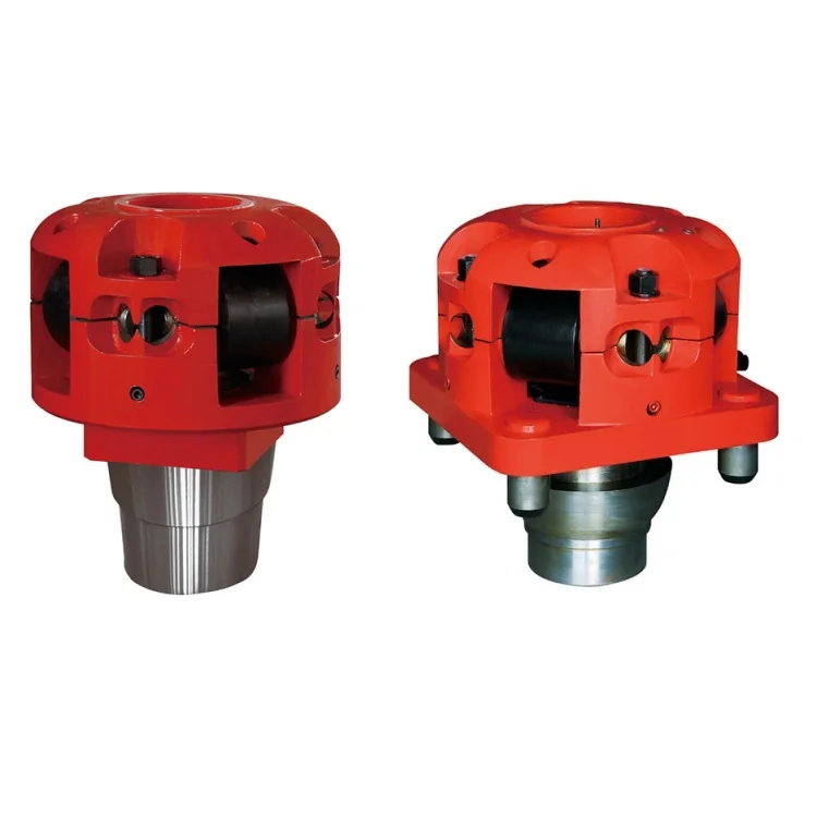
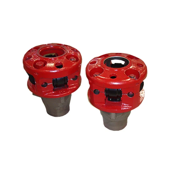
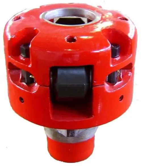
Kelly bushing is that elevated device positioned right on top of the rotary table and used to transmit torque from the rotary table to the kelly. The kelly bushing is designed to be the connection between the rotary table and the kelly. The kelly is a 4 or 6 sided steel pipe.
The purpose of the rotary table is to generate the rotary action (torque) and power necessary to rotate the drillstring and drill a well. The torque generated by the rotary table is useless if it is not transferred to the kelly (the drillstring is connected to the kelly).
Hence, through the kelly bushing the torque generated at the rotary table is transferred to the kelly. To achieve this connection, the inside profile of the kelly bushing matches the outer profile of the kelly so that the kelly fits or “sits” comfortably in the kelly bushing.
There are various designs for the kelly bushing including the split type, the pin-drive type and the square-drive type. Each of these designs has different ways in which they are connected and disconnected from the rotary table.
The internal diameter of the kelly bushing can be cut into the shape of a square (4-sided) or a hexagon (6-sided) depending on the outer shape of the kelly that will be used. The internals of a Kelly bushing is designed to resemble the outer shape of a Kelly just like the insides of a key lock is cut to exactly match the outer shape of the key.
The kelly bushing is not designed to hold tightly onto the Kelly; the kelly is still permitted to move up and down through the kelly bushing. This requirement is a must since drilling cannot progress if the kelly remains on a fixed spot. As the well is drilled deeper, the kelly also moves downward through the Kelly bushing.
The kelly bushing is sometimes used as a reference point from which depth measurements can be taken. All depths must be recorded with respect to a reference point; the kelly bushing (KB) is one of the depth references used in the oil and gas industry.
The top of the kelly bushing is normally used as the depth reference.For example, 7500ft KB means 7500ft below the kelly bushing or 7500ft measured from the top of the kelly bushing down to that point in the well.
In some other cases, depths could be recorded as 7500ft MDBKB meaning 7500ft measured depth below the kelly bushing. This is mostly used when the measured depth is different from the true vertical depth of the well, common with deviated and horizontal wells.
Start shopping at Alibaba.com to discover wholesale rotary kelly bushing at incredible prices.Browse through rotary kelly bushing for any type of vehicle.Bearings can be produced from a broad variety of materials, such as different steel, rubber, plastic, brass, and ceramic. These materials, each having their own benefits that render them appropriate to specific operations, including noise level, mass, weight, capacity, and resistance, and a series of options to match your individual needs and requirements.
This particular type of rolling component has had a lengthy lifespan, originally made popular in bicycles then, automobiles. It decreases spinning rubbing while withstanding axial and radial loads and has the potential to be used across a broad spectrum of different industries, of which aerospace, agricultural and machinery, wagons and other automobiles, skateboards, and of course fidget spinners!
However, getting a bushing that is properly functioning is critical to a comfortable and smooth ride, as they maintain the car in good conditions. We have variously available bushings including, grounding bushing, polyurethane bushings, energy suspension bushings, brass bushings, and even drill bushings.Buy our selection of rotary kelly bushing now. For those of you who are looking for quality wholesale rotary kelly bushing at a bargain price, well then you should look no further! At Alibaba.com, you may find a great array of quality automotive accessories and everything at an awesome price.
The square or hexagonal shaped steel pipe connecting the swivel to the drill string. The kelly moves through the rotary table and transmits torque to the drill string.
Source: API RP 7G, Recommended Practice for Drill Stem Design and Operating Limits, Upstream Segment, Sixteenth Edition, August 1998 (Addendum 2: September 2009). Global Standards
Square- or hexagonal-shaped steel pipe connecting the swivel to the drill pipe. NOTE The kelly moves through the rotary table and transmits torque to the drill stem.
Square or hexagonally shaped steel pipe connecting the swivel to the drill pipe that moves through the rotary table and transmits torque to the drill stem.
The square, hexagonal or other shaped steel pipe connecting the swivel to the drill pipe. The kelly moves through the kelly bushings, rotary table and rotates the drill string.
Source: API RP 54, Recommended Practice for Occupational Safety for Oil and Gas Well Drilling and Servicing Operations, Third Edition, August 1999 (2007). Global Standards
The uppermost component of the drill string; the kelly is an extra-heavy joint of pipe with flat or fluted sides that is free to move vertically through a “kelly bushing” in the rotary table; the kelly bushing imparts torque to the kelly and thereby the drill string is rotated.
The uppermost component of the drill string; the kelly is an extra-heavy joint of pipe with flat or fluted sides that is free to move vertically through a “kelly bushing” in the rotary table; the kelly bushing imparts torque to the kelly and thereby the drill string is rotated.
Source: API RP 64, Recommended Practice for Diverter Systems Equipment and Operations, Second Edition, November 2001 (March 1, 2007). Global Standards
“Kelly” means a 3 or more sided shaped steel pipe connecting the swivel to the drill pipe. The kelly moves through the kelly bushing and the rotary table and transmits torque to the drill string. [Mich. Admin. Code R 408 (2013)].
The square or other shaped steel pipe connecting the swivel to the drill pipe. The kelly moves through the rotary table and transmits torque to the drill string.

A 27-year-old gas drilling rig worker died on May 23, 2003 from blunt force trauma to the head, neck, and chest during a cleanout operation at the well. At the time of the incident, the victim was working within eight feet of the kelly on the drilling rig floor. Compressed air was used to blow out the conductor pipe, but due to a lack of communication, the compressor was turned on before the valves were prepared to control the flow of debris out of the hole. The excess pressure caused the kelly bushing, drillpipe slips, and debris to be blown out of the rotary table. The victim was struck by these objects and was pronounced dead on arrival to the hospital.
Ensure that all employees are trained properly and possess the skills necessary to recognize and control hazards for all operations in which they participate.
A 27-year-old gas drilling rig worker died on May 23, 2003 from blunt force trauma to the head, neck, and chest after he was struck by the kelly bushing and drillpipe slips. OKFACE investigators reviewed the death certificate, related local news articles, and reports from the sheriff’s office, Medical Examiner, Occupational Safety and Health Administration (OSHA),
and emergency medical services (EMS). Interviews were conducted with company officials, including safety representatives, at the company headquarters on August 19, 2003.
The drilling company that employed the decedent had been in business for 33 years and, at the time of the incident, employed 140 individuals. The victim had five years of experience in drilling operations and had worked for this drilling company off and on over that five-year period. However, during this time of employment, he had been working for the employer for only three days. At the time of the incident, the decedent was part of a five-person crew that was working at a gas well site, which had been in operation for three days (Figure 1). The victim was fatally injured during a cleanout operation. The cleanout process is a normal part of drilling operations and involves blowing out mud, water, and debris by pressurizing the well shaft with either air or liquid as the standard cleaning media. The victim had performed the cleanout process many times in the past.
The company did have a comprehensive written safety program in place at the time of the incident. The victim had received formal company safety training and informal on-the-job training specifically relating to cleanout operations. Safety meetings were held regularly, and levels of training were measured by employee testing and demonstration. Two of the five workers at the site had recently joined the crew from other drilling companies; however, they each had years of experience in oil and gas drilling.
At the time of the incident, the rig floor and working surfaces were level and dry; the weather was warm with light to no wind. The victim was working with four other crew members on a gas drilling rig, wearing the necessary personal protective equipment (e.g., steel toe boots, hard hat, eye protection). Prior to the incident, the decedent was assigned the task of driller and was asked to find the bottom of the conductor hole with the kelly (Figure 2). The kelly is used to transmit power (rotary motion) from the rotary table and kelly bushing to the drillstring (Table 1). After unlatching the brake handle, the driller allowed the kelly to free fall to the bottom. The uncontrolled fall caused the kelly to become jammed with debris, such as water, mud, and other material, that had collected in the conductor hole since the time it was originally drilled for the well. As a result, a cleanout operation became necessary. Cleanout procedures involving air or mud drilling fluid are acceptable norms in the oil and gas drilling industry; however, drilling fluid is more commonly used than compressed air.
a long square or hexagonal steel bar with a hole drilled through the middle for a fluid path; goes through the kelly bushing, which is driven by the rotary table
After the kelly became jammed, a senior driller was assigned to take over the brake handle and kelly; however, the decedent remained approximately eight feet away on the rig floor. A newly hired, yet experienced, derrickman had the job of running the air compressor. While the drillers were switching positions, the derrickman realized that he had not started that particular type of compressor in quite some time and left the rig floor to seek help from another driller onsite.
In normal cleanout operation procedures, certain valves are closed prior to turning on the compressed air, which allows control over the flow of debris out of the hole and into a catch pond. Once the valves are prepared, the driller indicates to the derrickman that the area is ready for the compressed air. At some point between the senior driller preparing for cleanout and the derrickman leaving the floor to turn on the air compressor, there was a lack of communication and the air compressor was activated without the senior driller’s knowledge, prior to the prescribed valves being shut. After starting the air compressor, the derrickman returned to the rig floor and, as he walked to his next assignment, the rotary table erupted. The pressure normally used to complete the cleanout work is a minimum of 20 pounds per square inch. Within minutes, the kelly had pressurized well beyond this point to 150 pounds per square inch. The victim, who was still on the rig floor in close proximity to the kelly, was also unaware that the air compressor had been turned on. The compressed air, at full pressure with no valves closed to control or direct the flow, blew the kelly bushing, drillpipe slips, and debris out of the rotary table; all of which struck and landed on the victim.
The victim was the only crew member injured by the flying debris and equipment. The victim was pulled away from the hazardous area, laid down, and kept calm. There was some initial confusion over whom to call for help, which caused a lack of quick medical response. Apparently no emergency numbers were posted on-site; although, a cell phone was available, there may have been some trouble getting through. One of the crew members went to the nearest farmhouse to find out how to call local EMS, while another was sent out to the road to direct first responders. EMS arrived at the scene approximately 30 minutes after the incident and loaded the victim for transport to the hospital. The victim was pronounced dead on arrival to the hospital, which was approximately 20 miles away.
Discussion: Employers should develop, implement, and enforce standard operating practices and procedures for all drilling operations to safeguard against unexpected energization or startup of equipment/machinery, or hazardous energy release during servicing and maintenance. These written practices and procedures should be reviewed at least annually. In this incident, standard operating procedures for performing cleanout, and training to those procedures, were needed to help monitor air and hydraulic pressure and control pumps and compressors. Had a standard written operating procedure been in place and complied with by the crew, this incident may have been prevented. While using compressed air is a normal cleanout practice, the area around the rotary table becomes highly hazardous during the procedure and requires certain precautions, such as following each step in order, knowing where debris will go before the air is started, and clearing crew members from dangerous areas. With enforced, documented procedures, the chances of inadvertent hazardous energy release are reduced.
Recommendation #2: Employers should monitor all job tasks to ensure that employees are not directly positioned in areas that are subject to flying parts, debris, and other hazards.
Discussion: The employer and designated site supervisors should monitor the site for hazardous situations and non-compliance. Any deviations from written job procedures or safety standards, or any unsafe situations that arise from site-specific work, should be addressed by management and corrected immediately. All employees should take steps to address unsafe work procedures and to eliminate them by accepted means of control or modification, including, but not limited to, engineering controls, work practice controls, and the use of personal protective equipment. Employees should be aware of how they are positioned at all times to avoid standing, sitting, or working in hazardous zones.
Recommendation #3: Employers should ensure that all employees are trained properly and possess the skills necessary to recognize and control hazards for all operations in which they participate.
Discussion: Employees should be trained thoroughly and formally on the standard operating procedures that are relevant to their duties and assignments. In addition, employers should consider thorough skill evaluations or screening for functional skills prior to hire or work assignment. For operations, such as performing cleanout on a drilling rig, the potential hazards of blowouts during the operation should be addressed, as well as ways to minimize or eliminate the hazards. In addition, training should emphasize the importance of establishing and maintaining good communication between all crew members while performing all work procedures. Documentation of the training should be kept on file with the company, and periodic retraining of employees should be done. Retraining should always occur when there are changes in the equipment, processes, or hazards present. Oil and gas industries should consider consulting sources such as publications from the International Association of Drilling Contractors (IADC; http://www.iadc.org/external icon) (Link Updated 4/1/2013) and OSHA’s Oil and Gas Well Drilling and Servicing eTool (https://www.osha.gov/SLTC/etools/oilandgas/ general_safety/general_safety.htmlexternal icon) for information on safety and training.
Recommendation #4: Employers should develop and utilize a written emergency action plan and should train employees on site-specific emergency response plans.
Discussion: The emergency action plan should be in written form and include all necessary steps to take when an emergency occurs. The plan should contain steps for providing emergency first aid and cardiopulmonary resuscitation (CPR), the phone numbers for all emergency providers and appropriate company officials, and the proper documentation forms to complete following an emergency. The plan should also address fire evacuation and prevention, severe weather procedures, and workplace violence and safety. Every employee should be trained annually on the company’s emergency action plan. Information should be provided on the scope, purpose, and application of the plan. Site-specific information (e.g., severe weather shelters, fire evacuation plan, location of nearest medical care facilities, and pertinent contact phone numbers) should be given to or posted for employees each time a rig is moved. Employees should know where copies of site-specific plans are kept and who to notify if the plans are not readily available. In addition, remote jobsites should have cell phones, two-way radios, or other reliable means of quick communication in the event of an emergency.
Occupational Safety and Health Administration. Oil and Gas Well Drilling and Servicing eTool. (https://www.osha.gov/SLTC/etools/oilandgas/general_safety/general_safety.htmlexternal icon)
The Oklahoma Fatality Assessment and Control Evaluation (OKFACE) is an occupational fatality surveillance project to determine the epidemiology of all fatal work-related injuries and identify and recommend prevention strategies. FACE is a research program of the National Institute for Occupational Safety and Health (NIOSH), Division of Safety Research.
These fatality investigations serve to prevent fatal work-related injuries in the future by studying the work environment, the worker, the task the worker was performing, the tools the worker was using, the energy exchange resulting in injury, and the role of management in controlling how these factors interact.
To contact Oklahoma State FACE program personnel regarding State-based FACE reports, please use information listed on the Contact Sheet on the NIOSH FACE website. Please contact In-house FACE program personnel regarding In-house FACE reports and to gain assistance when State-FACE program personnel cannot be reached.

A large valve, usually installed above the ram preventers, that forms a seal in the annular space between the pipe and well bore. If no pipe is present, it forms a seal on the well bore itself. See blowout preventer.†
One or more valves installed at the wellhead to prevent the escape of pressure either in the annular space between the casing and the drill pipe or in open hole (for example, hole with no drill pipe) during drilling or completion operations. See annular blowout preventer and ram blowout preventer.†
A heavy, flanged steel fitting connected to the first string of casing. It provides a housing for slips and packing assemblies, allows suspension of intermediate and production strings of casing, and supplies the means for the annulus to be sealed off. Also called a spool.†
A pit in the ground to provide additional height between the rig floor and the well head to accommodate the installation of blowout preventers, ratholes, mouseholes, and so forth. It also collects drainage water and other fluids for disposal.†
The arrangement of piping and special valves, called chokes, through which drilling mud is circulated when the blowout preventers are closed to control the pressures encountered during a kick.†
A centrifugal device for removing sand from drilling fluid to prevent abrasion of the pumps. It may be operated mechanically or by a fast-moving stream of fluid inside a special cone-shaped vessel, in which case it is sometimes called a hydrocyclone.†
A centrifugal device, similar to a desander, used to remove very fine particles, or silt, from drilling fluid. This keeps the amount of solids in the fluid to the lowest possible level.†
The hoisting mechanism on a drilling rig. It is essentially a large winch that spools off or takes in the drilling line and thus raises or lowers the drill stem and bit.†
The cutting or boring element used in drilling oil and gas wells. Most bits used in rotary drilling are roller-cone bits. The bit consists of the cutting elements and the circulating element. The circulating element permits the passage of drilling fluid and uses the hydraulic force of the fluid stream to improve drilling rates.†
A heavy, thick-walled tube, usually steel, used between the drill pipe and the bit in the drill stem. It is used to put weight on the bit so that the bit can drill.†
The heavy seamless tubing used to rotate the bit and circulate the drilling fluid. Joints of pipe 30 feet long are coupled together with tool joints.†
A wire rope hoisting line, reeved on sheaves of the crown block and traveling block (in effect a block and tackle). Its primary purpose is to hoist or lower drill pipe or casing from or into a well. Also, a wire rope used to support the drilling tools.†
On diesel electric rigs, powerful diesel engines drive large electric generators. The generators produce electricity that flows through cables to electric switches and control equipment enclosed in a control cabinet or panel. Electricity is fed to electric motors via the panel.†
A large, hook-shaped device from which the elevator bails or the swivel is suspended. It is designed to carry maximum loads ranging from 100 to 650 tons and turns on bearings in its supporting housing.†
The heavy square or hexagonal steel member suspended from the swivel through the rotary table. It is connected to the topmost joint of drill pipe to turn the drill stem as the rotary table turns.†
A device fitted to the rotary table through which the kelly passes. It is the means by which the torque of the rotary table is transmitted to the kelly and to the drill stem. Also called the drive bushing.†
A portable derrick capable of being erected as a unit, as distinguished from a standard derrick, which cannot be raised to a working position as a unit.†
A series of open tanks, usually made of steel plates, through which the drilling mud is cycled to allow sand and sediments to settle out. Additives are mixed with the mud in the pit, and the fluid is temporarily stored there before being pumped back into the well. Mud pit compartments are also called shaker pits, settling pits, and suction pits, depending on their main purpose.†
A trough or pipe, placed between the surface connections at the well bore and the shale shaker. Drilling mud flows through it upon its return to the surface from the hole.†
A diesel, Liquefied Petroleum Gas (LPG), natural gas, or gasoline engine, along with a mechanical transmission and generator for producing power for the drilling rig. Newer rigs use electric generators to power electric motors on the other parts of the rig.†
A hole in the rig floor 30 to 35 feet deep, lined with casing that projects above the floor. The kelly is placed in the rathole when hoisting operations are in progress.†
The hose on a rotary drilling rig that conducts the drilling fluid from the mud pump and standpipe to the swivel and kelly; also called the mud hose or the kelly hose.†
The principal component of a rotary, or rotary machine, used to turn the drill stem and support the drilling assembly. It has a beveled gear arrangement to create the rotational motion and an opening into which bushings are fitted to drive and support the drilling assembly.
A series of trays with sieves or screens that vibrate to remove cuttings from circulating fluid in rotary drilling operations. The size of the openings in the sieve is selected to match the size of the solids in the drilling fluid and the anticipated size of cuttings. Also called a shaker.†
Wedge-shaped pieces of metal with teeth or other gripping elements that are used to prevent pipe from slipping down into the hole or to hold pipe in place. Rotary slips fit around the drill pipe and wedge against the master bushing to support the pipe. Power slips are pneumatically or hydraulically actuated devices that allow the crew to dispense with the manual handling of slips when making a connection. Packers and other down hole equipment are secured in position by slips that engage the pipe by action directed at the surface.†
A relatively short length of chain attached to the tong pull chain on the manual tongs used to make up drill pipe. The spinning chain is attached to the pull chain so that a crew member can wrap the spinning chain several times around the tool joint box of a joint of drill pipe suspended in the rotary table. After crew members stab the pin of another tool joint into the box end, one of them then grasps the end of the spinning chain and with a rapid upward motion of the wrist "throws the spinning chain"-that is, causes it to unwrap from the box and coil upward onto the body of the joint stabbed into the box. The driller then actuates the makeup cathead to pull the chain off of the pipe body, which causes the pipe to spin and thus the pin threads to spin into the box.†
A vertical pipe rising along the side of the derrick or mast. It joins the discharge line leading from the mud pump to the rotary hose and through which mud is pumped going into the hole.†
A rotary tool that is hung from the rotary hook and traveling block to suspend and permit free rotation of the drill stem. It also provides a connection for the rotary hose and a passageway for the flow of drilling fluid into the drill stem.†
The large wrenches used for turning when making up or breaking out drill pipe, casing, tubing, or other pipe; variously called casing tongs, rotary tongs, and so forth according to the specific use. Power tongs are pneumatically or hydraulically operated tools that spin the pipe up and, in some instances, apply the final makeup torque.†
The top drive rotates the drill string end bit without the use of a kelly and rotary table. The top drive is operated from a control console on the rig floor.†
Crane means any self-propelled vehicle to which has been permanently mounted or attached any crane, whether or not such vehicle was originally a truck, tractor, or other type of motor vehicle or was designed and built as a complete crane unit. However, the word "crane," as herein defined, shall not be construed to mean any truck or other vehicle equipped with or to which has been affixed any device used for the purpose of providing a means for towing other vehicles.
Roomer means a person occupying a dwelling unit that lacks a major bathroom or kitchen facility, in a structure where one or more major facilities are used in common by occupants of the dwelling unit and other dwelling units. Major facility in the case of a bathroom means toilet, or either a bath or shower, and in the case of a kitchen means refrigerator, stove or sink.
Sternlight means a white light placed as nearly as practicable at the stern showing an unbroken light over an arc of the horizon of 135 degrees and so fixed as to show the light 67.5 degrees from right aft on each side of the vessel.
Semitrailer means every vehicle without motive power designed for carrying persons or property and for being drawn by a motor vehicle and constructed so that some part of its weight and its load rests or is carried by another vehicle.
Loft means an intermediary floor on a residual space in a pitched roof; above normal floor level with a maximum height of 1.5 metres and which is constructed or adopted for storage purposes;
Dewatering means the removal of water for construction activity. It can be a discharge of appropriated surface or groundwater to dry and/or solidify a construction site. It may require Minnesota Department of Natural Resources permits to be appropriated and if contaminated may require other MPCA permits to be discharged.
Playground means a public outdoor recreation area for children, usually equipped with swings, slides, and other playground equipment, owned and/or managed by a city, county, state, or federal government.
handyman means an employee who makes minor repairs or effects renovations to buildings, fixtures and fittings and who covers ironing and pressing machines or tables with any type of materials;

The present invention relates in general to the art of drilling oil and gas wells and, more particularly, to the measurement of rotary torque and RPM for oil and gas drilling rigs.
In the drilling of oil and gas wells with rotary rigs, and, in particular, the drilling of deep wells, the drill pipe is subjected to considerable stress. The stress is imposed by the weight of the drill string, by the resistance of the strata to the rotation of the drill pipe and to the cutting action of the drill bit in the different strata. Care must be taken to control the amount of torque imposed on the drill string, otherwise twist-offs may occur which would result in expensive fishing jobs to retrieve the last portion of the drill string.
The measurement of rotary torque is used to observe pipe sticking, indicate bit wear and optimize drilling. The counting of total revolutions of the drill string can give wear-life data to help prevent failure while drilling. RPM, used with rotary torque, weight on bit and rate of penetration, can be used to calculate factors that give valuable drilling data. The present invention provides a system for the transmission of rotary torque and real time revolutions from the rotary table/Kelly combination of an oilfield or other rotary drilling rig. Real time revolutions allow the RPM to be calculated.
The prior art measurement of rotary torque and revolving speed utilizes two, usually separate, transducer systems. Rotations are sensed by proximity switches which are closed each revolution. This method is commonly used, however, the switches often get in the way of the driller. Another commonly used method is to use a take-off point in the rotary chain drive and an electrical tachometer-generator. This method has the drawbacks of having to scale the output voltage and/or frequency in order to determine true revolutions. Either method is commonly used by wiring the transducer to the readout mechanism. Rotary torque is often measured by means of tension measurement in the rotary drive chain, accessible only from beneath the rig floor and rotary table.
In U.S. Pat. No. 3,664,184 to Norman D. Dyer, patented May 23, 1972, a rotary torque indicator for well drilling apparatus is shown and described as follows. The device is used to indicate torque applied by the rotary table to the drill string during drilling of oil and gas wells. An intermediate adapter between the Kelly bushing and the rotary table in one embodiment has two parts. The lower part of the adapter includes a standard male square drive that fits into the square drive of the rotary table, and is thus rotated by the rotary table. The upper part of the adapter includes a female square drive arranged to receive the male square drive on the Kelly. The Kelly transmits torque from the adapter assembly to the drill pipe. The upper part is connected to the lower part by either hydraulic cylinders or by linkage with strain gauge. The upper part rotates with the lower part, but is moveable relative thereto to indicate relative torque between the upper and lower parts. An R.F. transmitter connected to the hydraulic cylinder or strain gauge provides a torque signal to a remote R.F. receiver. An alternative embodiment has a unitized adapter assembly. Still another alternative embodiment uses a torque sensor and R.F. transmitter directly on the Kelly drive bushing without utilization of an intermediate bushing.
In U.S. Pat. No. 3,691,825 to Norman D. Dyer, patented Sept. 19, 1972, a rotary torque indicator for well drilling apparatus is shown and described as follows. This device is used to indicate torque applied by the rotary table to the drill string during drilling of oil and gas wells. An intermediate adapter between the Kelly bushing and the rotary table in one embodiment has two parts. The lower part of the adapter includes a standard male square drive that fits into the square drive of the rotary table, and is thus rotated by the rotary table. The upper part of the adapter includes a female square drive arranged to receive the male square drive on the Kelly. The Kelly transmits torque from the adapter assembly to the drill pipe. The upper part is connected to the lower part by either hydraulic cylinders or by linkage with a strain gauge. The upper part rotates with the lower part, but is moveable relative thereto to indicate relative torque between the upper and lower parts. An R.F. transmitter connected to the hydraulic cylinder or strain gauge provides a torque signal to a remote R.F. receiver. An alternative embodiment has a unitized adapter assembly. Still another alternative embodiment uses a torque sensor and R.F. transmitter directly on the Kelly drive bushing without utilization of an intermediate bushing.
The present invention provides a system for measuring the rotary torque and RPM of a rotary drill string. An intermediate adapter is positioned between the Kelly and the rotary table. A strain gauge is attached to the intermediate adapter to measure torsional deformation and provide an indication of rotary torque. Transmission of torque data is accomplished by radio frequency transmission utilizing a transmitter on the intermediate adapter. A receiver is mounted to the side of the drill rig floor to receive and demodulate the torque signal. The intermediate adapter is rotating at the same rate as the drill string. Detection of revolutions of the drill string is accomplished at the edge of the drill rig platform or elsewhere with a stationary sensor which doubles as the torque receiver. A highly directional torque transmitter antenna mounted on the adapter is used with the major lobe parallel to the rig floor and perpendicular to the drill pipe. By detecting the envelope of the radio frequency field strength, each rotation is marked by a peak. This enables continuous torque and RPM monitoring. The foregoing and other features and advantages of the present invention will become apparent from a consideration of the following detailed description of the invention when taken in conjunction with the accompanying drawings.
Referring now to the drawings and, in particular, to FIG. 1, an embodiment of the present invention is illustrated in conjunction with an oil well drilling rig 10 and a rotary drill string 11 used in an oil well drilling operation. A well bore 12 is shown having a casing 13. The rotary drill string 11 is provided with a drill bit 14 at its lower end. The drill string 11 is rotated by a rotary table 15 mounted in the derrick 16. Drilling mud is pumped from a mud pit 17 through line 18 by pump 19. The mud is pumped into the drill string 11 and is discharged out of the bit 14 into the well bore 12. The mud continues upward in the well bore 12 and is returned from the top of the casing 13 by a mud flowline 20 to the mud pit 17. An openable and closeable blowout preventer or rotary drill head of any suitable conventional type is provided at the upper end of the casing 13.
The drill string 11 is attached to the lower end of the drive Kelly 21. An intermediate adapter 22 is positioned between the Kelly 21 and the rotary table 15. Enlarged views of the intermediate adapter 22 are shown in FIGS. 2 and 3. The adapter 22 rotates with the drill string/Kelly combination and transmits all of the torque from the rotary table 15 to the Kelly 21. The mechanical portion is a one-piece adapter with one end 23 that fits into the square rotary table drive bushing. The other end 24 accepts the square shoulder of the Kelly drive. Between the two ends is a tubular section 25 that allows the Kelly 21 to pass through. The material and thickness of this tubular section 25 must be chosen so that the torque range transmitted through the adapter 22 is sufficient to achieve a measurable elastic strain deformation yet be totally safe from structural failure. This type of Kelly adapter is described in U.S. Pat. Nos. 3,664,184 and 3,691,825 by Norman Dyer.
For a one-piece adapter, a strain gauge torsional sensor is used. A two-piece unit engaged to compress a load cell may also be used to indicate torque, as described in the Dyer patents. Since all torque is transmitted through the adapter 22 calibration is independent of the rig it is installed in. This is an advantage over other types of sensors. Transmission of signals is accomplished by radio frequency telemetry, allowing maximum freedom from physical interconnections. Prior art methods of RPM and torque measurement require sensors mounted in physically inconvenient locations, i.e. under the drilling rig floor, and required semi-permanent wiring or hydraulic connections. Calibration of the prior art sensors is required and must be done on location where standards to calibrate against are frequently unavailable. The present invention allows easy installation at any time and is calibrated independently of the installation, so that calibration to a standard for torque is possible, and output in true revolutions can be determined without having to obtain ratios and scale factors as must now be done for prior art tachometer-generators commonly used.
The transmission of the torque and RPM information from the adapter 22 to a receiver 27 is illustrated in FIG. 4. A top view of the floor of the drilling rig 16 is illustrated. The analog strain value is converted to a frequency and the frequency is used to f-m modulate the carrier frequency. The radio frequency chosen is based on interference, regulations and acceptable antenna dimensions. The transmitter may be low powered since the usual distance to be transmitted is less than 100 feet. The receiver 27 mounted to the side of the drill rig floor will receive and demodulate the torque and RPM signal. Since the adapter 22 is rotating at the same rate as the drill string and rotary table, simultaneous torque detection and revolutions of the rotary table are obtained. The revolutions may be detected at the edge of the drill rig platform with a stationary sensor which doubles as the torque receiver. A highly directional torque transmitter antenna is mounted on the adapter with the major lobe lying parallel to the rig floor and perpendicular to the drill pipe. By detecting the envelope of the R.F. (radio frequency) field strength, each rotation is marked by a peak. This enables continuous torque and RPM monitoring.
Referring now to FIGS. 5-8, the torque sensor 28 and a wireless transmitter transmits the torque applied through the adapter 22. This may be accomplished utilizing 91.75 MHz commercially available FM transmitters, such as are available from Aerotherm Corporation. Higher frequencies, such as 217 MHz require more convenient antenna dimensions and are in frequency bands allocated for such service.
FIG. 6 shows the associated receiver for the transmitter of FIG. 5. The operation is as follows: Battery power source 31 powers all active components of the torque transmitter of FIG. 5. Load cell 28, which may also be a strain bridge or other device to determine torque as described in the Dyer patent, is amplified by amplifier 52, which may be commercially available or built from integrated circuit op amps such as Fairchild μA725. A frequency-to-voltage converter 29, such as may be built with Raytheon Semiconductor"s RC4151 converts the torque voltage signal to an equivalent frequency, i.e., in the range of 0-10,000 Hertz. The 217 MHz FM transmitter 34, similar in function to "FM Wireless Mike", Markus, Sourcebook of Electronic Circuits 1968, p. 802 is used to transmit the frequency signal 33 through the directional antenna 36. This antenna is arranged so that one or more of its directional lobes lie in a plane parallel to the rig floor and perpendicular to the drill string. In this manner, the lobes will sweep over the rig floor once each revolution of the Kelly/drill string assembly. An example of a one-lobe antenna is the well-known dish-type antenna; a simple horizontal centerfed dipole has two lobes.
The block diagram of the receiver is shown in FIG. 6. Its directional antenna 38 is pointed toward the drill string/Kelly assembly. FM discriminator/demodulator 47 converts the torque data back to a frequency; then frequency-to-voltage converter 48 (utilizing an RC4151) converts the frequency to analog torque at line 49. Alternately, a counter and time base can digitize torque. Envelope detector 40, which consists of a semiconductor diode 41, filter capacitor 42, and decay resistor 43, follows the envelope of the R.F. signal giving an indication of strength. The RC time constant should be larger than the modulation period, but much less than the fastest expected rotating period of the Kelly. A threshold detector 45, which may consist of an integrated circuit op amp wired as a D.C. comparator, can detect each R.F. signal strength period. For good noise immunity, a Schmitt trigger should be used, and the trigger level set by the relative average signal strength. If the Kelly transmitter antenna has more than one lobe, then there will be one output pulse per lobe per revolution. The combination of FIGS. 5 and 6 provide a system which receives torque data continuously, and has a logic output at every revolution.
Modifications may be made to the above described system without departing from the invention. For example, an AGC (automatic gain control) may be utilized using National Semiconductor"s LM 370 to hold the peak R.F. envelope to a fixed value. The comparator threshold could be fixed and would require little or no adjustment. This would also enable the FM discriminator to have an adequate signal to process.
Another embodiment will be described that has the advantages of requiring less battery energy in the Kelly electronics. This reduces either the battery size or the required service interval. The block diagram for this system is shown in FIGS. 7 and 8 showing the Kelly package and the fixed rig-mounted package. Antennas 52 and 67 are highly directional one lobe antennas, aimed in the same manner as the previously described embodiment so that they achieve maximum gain relative to each other once per revolution. The torque receiver is shown in FIG. 8. It contains a transmitter at a different frequency (i.e. 173.2 MHz) than the torque data transmitter. It is continuously modulated in an amplitude modulation scheme by a signal generator 77, driving AM transmitter 79. A diplexer 68 allows antenna 67 to both receive torque data through line 69 and transmit trigger signal through line 80 at 173.2 MHz.
The Kelly unit has a low power receiver 55 which is tuned to 173.2 MHz and has a band-pass filter tuned to the periodic generator 77 in the data receiver"s transmitter. When the 173.2 MHz signal exceeds a threshold, the receiver "switches", firing a one-shot unit 57, this switching action may be accomplished by a preset trigger threshold or by a dynamic threshold which follows the average level of the input R.F. signal and thus discriminates against noise.
Upon switching, one shot unit 57 powers the sensor 59 which may be a strain gauge or load cell, signal amplifier and conditioner 60, voltage-to-frequency converter 63 and FM transmitter 65. The action of these components is the same as components to 28, 52, 29, 34, 36 of FIG. 5 described previously. The FM modulated signal carries data information and is transmitted through antenna diplexer coupler 53 which allows use of antenna 52 for both transmitting and receiving.
When the FM receiver 70 shown in FIG. 8 detects a signal, two things happen. The receiver AGC (automatic gain control) changes to indicate the relative field strength. This action may be "cleaned" to a good logic signal by Schmitt trigger 72, similar to Motorola Semiconductors MC14093. Thus since there is data transmission once each revolution of the Kelly, the antennas couple once and there is one 217 MHz transmission. Thus each logic output of Schmitt trigger 72 indicates one revolution.
The data is derived as a frequency signal proportional to torque by the receiver"s FM discriminator. An F-V converter 75 converts it to an analog signal, or a digital counter and time base can convert it easily to a digital value. Since the value only exists while being transmitted, a memory device is required to hold the last value. This may be a sample-and-hold device 82 triggered by the revolution output on line 73 to hold the data after that. A digital memory may be used and will have more ideal memory. Wherever a revolution signal 73 is detected, the memory should be refreshed by the current R.F. torque data being transmitted from the Kelly.
The 173.2 MHz R.F. interrogation signal is on continuously. The directional Kelly antenna sees a peak every revolution when the antenna radiation patterns couple. The switch receiver puts out a series of pulses, one for each peak in the interrogation signal. Finally, the 217 MHz bursts are seen by the torque receiver. The length of the burst is long enough so that the V-F unit 63 can settle to a specific accuracy, but short enough to conserve battery power and only be on while the antennas remain coupled by their position.
It would also be possible to provide an antenna system mounted in the Kelly so that its phase angle would be constantly changing relative to the receiver. The receiver would monitor the phase cancellations and reinforcements and determine the occurrence of each revolution. It is also possible to monitor revolutions only, by not modulating the R.F. signal from the Kelly assembly. In this case, the Kelly adapter is not necessary and the electronics (transmitter and antenna) may be mounted directly to the Kelly or Kelly bushing. From indications of each rotation, conventional rate meters may be used to indicate rotary rate in RPM. Such meters may be a SWACO Div. of Dresser Industries Combination Pump Stroke Rate Meter/Counter, which has the capability of determining RPM of an input signal closure rate.
A rotary table is a mechanical device on a drilling rig that provides clockwise (as viewed from above) rotational force to the drill string to facilitate the process of drilling a borehole. Rotary speed is


 8613371530291