
rotary kelly bushing factory

Start shopping at Alibaba.com to discover wholesale rotary kelly bushing at incredible prices.Browse through rotary kelly bushing for any type of vehicle.Bearings can be produced from a broad variety of materials, such as different steel, rubber, plastic, brass, and ceramic. These materials, each having their own benefits that render them appropriate to specific operations, including noise level, mass, weight, capacity, and resistance, and a series of options to match your individual needs and requirements.
However, getting a bushing that is properly functioning is critical to a comfortable and smooth ride, as they maintain the car in good conditions. We have variously available bushings including, grounding bushing, polyurethane bushings, energy suspension bushings, brass bushings, and even drill bushings.Buy our selection of rotary kelly bushing now. For those of you who are looking for quality wholesale rotary kelly bushing at a bargain price, well then you should look no further! At Alibaba.com, you may find a great array of quality automotive accessories and everything at an awesome price.

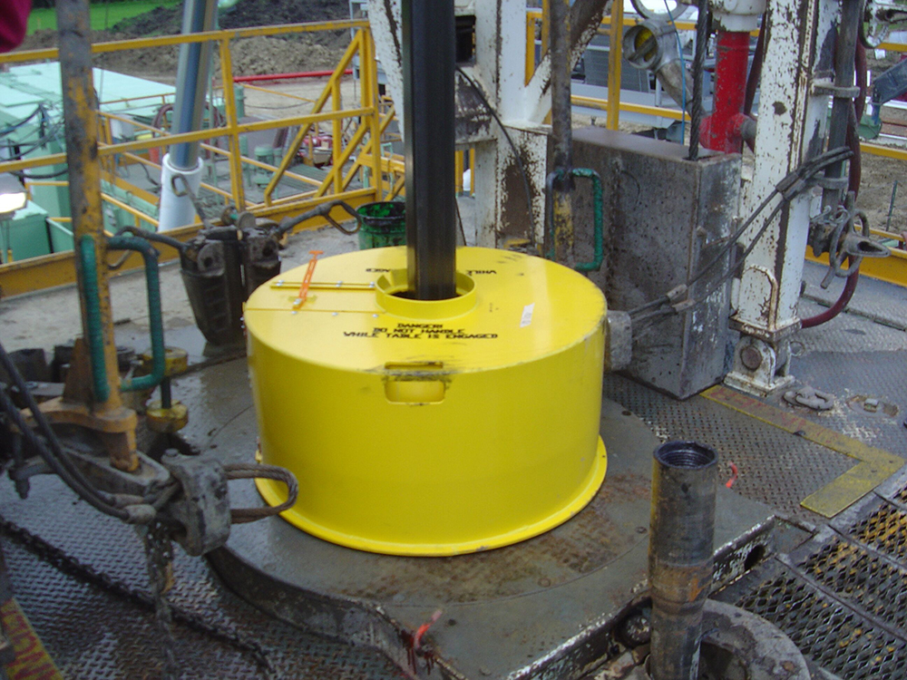
The Kelly Drive Bushing acts as an adapter that serves to connect the rotary table to the Kelly. The Kelly bushing has an inside diameter profile that matches that of the Kelly, usually square or hexagonal. It is connected to the rotary table by four large steel pins that fit into mating holes in the rotary table. The rotary motion from the rotary table is transmitted to the bushing through the pins, and then to the kelly itself through the square or hexagonal flat surfaces between the Kelly and the Kelly drive bushing. The Kelly then turns the entire drillstring because it is screwed into the top of the drillstring itself.
MASTER BUSHING AS SEMBLY Original Filed Jan. 4, 1967 United States Patent Int. Cl. F16d 3/06 US. Cl. 6423.5 17 Claims ABSTRACT OF THE DISCLOSURE An improved master bushing assembly capable of selectively driving either a pin drive kelly bushing or a square drive kelly bushing.
Master bushings presently in use in the well drilling industry are of two general types, namely: those which function to drive a square drive kelly bushing; and those which function to drive a pin drive kelly bushing. Although it is desirable to have both the square and pin type master bushings vailalble to the same rig concurrently, some operators cannot hear the expense involved in equipping themselves so fully. Additionally, if an operator does have both type master bushings available and drilling conditions dictate a desired change from a pin to a square drive kelly bushing or conversely, this necessitates the removal of the existing master bushing, for example a pin type, and inserting a square type in place thereof within the rotary table, thereby resulting in increased operation costs.
The present invention comprises a master bushing which, when used in conjunction with adapter means and/ or spacer means, permits selective use of a pin drive or square drive kelly bushing without the need to change the master bushing as is required with conventional master bushings.
FIG. 1 is a perspective view of a master bushing as,- sembly embodying one form of the present invention showing elements disassembled from one another;
FIG. 2 is a front elevational view partly in section of the embodiment illustrated in FIG. 1 showing certain of the elements thereof operatively assembled together with ments" thereof operatively assembled together with a rotary table and a square drive kelly bushing.
type master bushing assembly 10 comprising a master bushing 11 used in conjunction with a polygonal drive adapter, shown as a square drive adapter, insert 12 and a; pin drive type master bushing assembly 10" comprising the master bushing 11 used in conjunction with a pin drive spacing adapter insert 113. FIG. 2 shows master bushing assembly 10 arranged to be rotatably driven in a well known manner in a suitably rotatably driven rotary table 13 which rotary table is suitably supported by a rotary table frame 14. A polygonal drive, shown as a Patented Sept. 8, 1970 square drive, kelly bushing 15 engaging a swivel supported kelly 16 for rotation about its longitudinal axis while at the same time permitting relative vertical movement of the kelly 16 to advance a connected drill string downwardly within a well, is suitably received in the square drive adapter insert 12. A familiar stabbing skirt 17 extends downwardly from a downwardly extending centrally disposed square drive 42 fixed to the under surface of the main body portion 43 of the kelly bushing 15. The master bushing assembly 10 coacts with the kelly bushing 15 "for rotatably driving the kelly bushing 15.
The rotary table 13 includes a rigid tubular body section 18 supported in rotary table frame 14 by bearings 19 for rotation about its vertically extending longitudinal axis. The body section 18 has a lower cylindrical opening 20 and a larger upper generally square shaped opening 21 which together with lower opening 20 defines a generally square horizontal annular shoulder 22. The upper opening 21 extends up to the horizontal upper surface 23 of the rotary table 13.
The master bushing 11 includes a rigid tubular cylindrically externally shaped main body portion 25 complementary in external shape with and snugly received by lower portion 20 of rotary table 13. The inner opening 26 of body portion 25 is generally cylindrically shaped. A generally square shaped bevelled-corner flange 27 is fixed to the upper end portion of main body portion 25 and extends outwardly therefrom. Flange 27 has a generally flat horizontal upper surface 28 which, when master bushing -11 is interfitted with rotary table 13, is coplanar with the horizontal upper surface 23 of rotary table 13. Flange 27 also has a centrally disposed generally polygonal, as shown square, shaped recess 29, extending therewithin, which recess 29 has its center point coincident with the longitudinal axis of main body portion 25 and is greater in its side dimension than the diameter of inner opening 26, so that an annular shoulder 30 is defined between recess 29 and inner opening 26. The outer shape of flange 27 is complementary in shape with and snugly and non-rotatably received by the upper opening 21 of rotary table 13 such that the undersurface of flange 27 and shoulder 22 abut. The flange 27 has four longitudinally extending identical cylindrical openings 31 uniformly spaced at the corner portions of the flange 27 which receive the pin drive means (not shown) therein, of a pin drive kelly bushing (not shown) of a well known construction.
The square drive adapter insert 12 has a dual function of accommodating slips together with serving as the drive adapter means of the present invention, and includes a tubular cylindrically externally shaped lower portion 34 comprised of two identical semi-cylindrical bodies 35. The outer surface of lower portion 34 is complementary in shape to the inner opening 26 of body portion 25 of master bushing 11 and is removably received therein. Lower portion 34 has a frusto-conical downwardly tapering inner opening 36 suitably shaped for receiving slips. A generally square shaped bevelled-corner flange 37 comprised of two identical halves 38 is fixed to and extends outwardly from the upper end of lower portion 34. The outer shape of the sides of flange 37 is generally complementary in shape with that of the sides of recess 29 of main body portion 25 of master bushing 11, such that flange 37 is snugly and non-rotatably received in recess 29 with the upper surface of flange 37 being coplanar with the upper surface 28 of flange 27 of master bushing 11. Flange 37 has a centrally disposed longitudinally extending generally polygonal, shown as square, shaped opening 40 therewithin, which opening 40 has a side dimension greater than the major diameter of inner opening 36 of lower portion 34 so that an annular shoulder 41 is defined between opening 40 and inner opening 36. Square opening 40 of flange 37 is suitably sized to snugly removably receive the square drive portion 42 of kelly bushing 15.
The pin drive spacing insert 113 is used in combination with bushing 11 when a pin drive kelly bushing (not shown) of a well known construction, is rotatably driven by having the pin drive means (not shown) thereof received in openings 31 of flange 27. Insert 113 is dimensionally identical to the drive adapter insert 12 hereinabove described, with the exception that insert 113 has a differently shaped interior opening than insert 12, namely a frusto-conical downwardly tapering inner opening 32, which is suitably shaped for receiving a pin drive kelly bushing tapered guide skirt (not shown) of a well known construction therein. The exterior contact surfaces of inserts 12 and 113 are identical, therefore, no further description of insert 113 is believed necessary and it will be received within master bushing 11 in exactly the manner insert 12 is received as hereinabove described.
In addition, the principles of this invention taught by the embodiment hereinabove described and shown in FIGS. 1 through 3 may be applied to a master bushing which can be classified as an adapter receiving chamber, that is it, in itself, will have no drive provisions on the flange thereof, but will provide support for a square drive adapter insert or a pin drive adapter insert. The square drive adapter will be identical to insert 12 hereinabove described, however, the pin drive adapter will differ from insert 113 hereinabove described in that it will have drive pin receiving openings within the upper outwardly extending flange thereof. In this case the master bushing need not have the large flange that is required if the drive pin receiving openings were to be located therein.
FIGS. 4 and 5 represent another embodiment of a polygonal, shown as square, drive master bushing assembly of the present invention generally indicated at 65, which comprises a pin drive master bushing 11, of a construction well known in the art, and a pin drive to polygonal, shown as square, drive adapter insert means, generally indicated at 52, which converts the pin drive master bushing 11 to the square drive master bushing assembly 65.
Since certain elements as shown in FIGS. 4 and 5 are identical to those of FIGS. 1 through 3, the same reference characters will be applied to corresponding elements. Master bushing 11 is dimensionally identical to the master bushing 11 hereinabove described and illustrated in FIGS. 1 through 3, with the exception that master bushing 11" has a differently shaped interior opening Within the flange 27, namely a cylindrical opening 50". Additionally, as shown in FIGS. 4 and 5 the master bushing 11" is suitably arranged to be rotatably driven by the rotary table 13 suitably supported by the rotary table frame 14. The exterior contact surfaces of master bushings 11" and 11 are identical, therefore, no further description of master bushing 11" is believed necessary and it will be received within the rotary table 13 in exactly the manner master bushing 11 is received therein as hereinbefore described with reference to the embodiment of this invention illustrated in FIGS. 1 through 3.
The drive adapter means 52 includes an upper rigid flat plate portion 54 and an insert bowl portion 60 extending downwardly from the underside of plate portion 54. The plate portion 54 has a centrally disposed generally polygonal shaped, shown as square shaped, opening 55 therewithin and has external dimensions substantially the same as the dimensions of flange 27 of main body portion of master bushing 11". Square opening 55 is suitably sized and shaped, and plate portion 54 has a suitable thickness such that the square drive portion 42 of the square drive kelly bushing 15 will be snugly and non-rotatably received in square opening 55 as will be shown hereinafter.
Four cylindrically shaped pins 56 extends downwardly from and are rigidly fixed to the corner regions of the undersurface of plate portion 54 with the respective longitudinal centerlines of such pins 56 being substantially parallel with the vertical centerline of plate portion 54. Pins 56 have outer diameters substantially the same as the inner diameters of openings 31 in flange 27 of main body portion 25 of master bushing 11, with pins 56 having a longitudinal length to be received in openings 31 such that the undersurface of plate member 54 is flush with the upper surface 28- of flange 27.
Insert bowl portion 60 comprises a rigid cylindrically externally shaped body 62 being externally complementary shaped with and snugly removably received within the inner opening 26 of the main body 25 of master bushing 11". An outwardly extending generally cylindrically shaped flange 63 comprises the upper portion of body 62, which flange 63 is integral with and extends downwardly from the underside of plate portion 54. The flange 63 has an external shape complementary with the shape of recess 50 of flange 27 of main body portion 25 of master bushing 11", such that flange 63 is snugly received in recess 50. The inner opening 64 of body 62 is shaped in a frustoconical downwardly tapering manner for accommodating slips.
With plate portion 54 being mated with the master bushing 11" by interfitting pins 56 in openings 31 and insert bowl portion 60 into opening 26 the lower surface of the main body portion 43 of kelly bushing 15 will abut the upper surface of plate portion 54 and the square drive portion 42 of kelly bushing 15 will be snugly received in opening 55 with the lower surface of square drive portion 42 being coplanar with the upper surface 28 of flange 27.
1. A master bushing comprising: a body member having an opening extending therethrough and an outer configuration of a form that said body member is closely and non-rotatively received within the central opening of a given rotary drilling table with the axes of said openings being coincident; said opening in said body member being of a form to non-rotatively receive an adapter insert completely therein; said body member being partially in the form of an outwardly extending flange portion at the end thereof last receivable within such a central opening; and said flange portion having a plurality of parallel externally accessible open bores of a size and orientation to receive the pins of a known pin drive kelly bushing therein.
2. A master bushing as specified in claim 1 having a spacing adapter inserted in said opening in said body member, said insert comprising: a member having an outwardly extending flange portion at the end thereof last receivable within said opening in said body member; said member having a downwardly depending bowl portion; and said member having a circular central opening extending therethrough for the guiding and centerin of a known pin drive kelly bushing.
4. A master bushing as specified in claim 1 having a driving adapter inserted in said opening in said body member, said insert comprising: a member having an outwardly extending flange portion at the end thereof last receivable within said opening in said body member; and said member having a central polygonal cross-sectional opening at the upper end thereof of a size and orientation to non-rotatively receive a drive portion of a known polygonal drive kelly bushing.
7. A master bushing assembly comprising: a body member having an opening extending therethrough and an outer configuration of a form that said body member is closely and non-rotatively received within the central opening of a given rotary drilling table with the axes of said openings being coincident; a driving adapter insert having an outer configuration of a form that said insert is non-rotatively received within said opening extending through said body member; and said insert having a central polygonal cross-sectional opening at the upper end thereof of a size and orientation to non-rotatively receive a drive portion of a known polygonal drive kelly bushing.
8. A drive adapter for downward insertion into a pin drive kelly bushing wherein said adapter comprises: a body member having an opening extending centrally therethrough, said body having a lower portion with an external configuration coaxial with said opening and complementary and slidably receivable in an insert bowl passageway of a known pin drive master bushing, said opening having a configuration at the upper end thereof for receiving the square drive portion of a square drive kelly bushing and a configuration extending downwardly from said upper end thereof for receiving slip member; and drive pins for drivingly cooperating with said known pin drive master bushing and said body member.
9. A master bushing assembly comprising a drive adapter as specified in claim 8 in combination with a pin drive master bushing wherein said main body upper end surface becomes coplanar with the upper surface of said master bushing upon being so inserted.
10. A master bushing assembly comprising: a master bushing having means for accommodating a selected one of a pin drive insert and a square drive insert therein in combination with said selected one of said inserts providing for driving connection to a kelly drive bushing.
11. A master bushing assembly as specified in claim 10 wherein said master bushing has an upwardly open through bore with a top portion of polygonal internal cross section.
12. A master bushing assembly as specified in claim 11 wherein said selected one of said inserts is a pin drive spacing insert having a top external profile of mating polygonal cross section with said through bore top portion.
13. A master bushing assembly as specified in claim 11 wherein said selected one of said inserts is a polygonal drive adapter insert having a top external profile of mating polygonal cross section with said through bore top portion and an upwardly open central recess of polygonal cross section mateable with a known polygonal drive kelly bushing.
15. An adapter insert for a pin drive master bushing, said adapter insert having drive pins thereon for drivingly mating with a known pin drive master bushing and said adapter having an internal upwardly open recess of polygonal cross section mateable with the polygonal drive portion of a known polygonal drive kelly bushing.
16. A master bushing assembly comprising: a pin drive master bushing in combination with an adapter insert as specified in claim 15 for prividing driving connection between rotary drilling table and a polygonal drive kelly bushing.

The kelly is a primary link between the drilling rig’s surface equipment and the bit, and is therefore a critical component of the rotary system. Although top drive systems have replaced kelly/rotary table combinations on many rigs, some knowledge of their manufacture and operation is useful.
Their angled surfaces, or drive flats, are designed to fit into a drive roller assembly on the kelly bushing, so that as the rotary table turns to the right, the kelly turns with it. To allow for normal right-hand rotation of the drill string, kellys have right-hand threads on their bottom connections and left-hand threads on their top connections.
The American Petroleum Institute has established manufacturing and design standards for kellys, and has included them in the follwoing publications:API RP 7G, Recommended Practice for Drill Stem Design and Operating Limits.
For a kelly to be efficient in turning the drill string, the clearance between its drive flat surfaces and the rollers in the kelly bushing must be kept to a minimum. Kellys most often wear out due to a rounding-off of the drive corners, as shown in Figure 1 (new kelly with new drive assembly) and Figure 2 (worn kelly with worn drive assembly).
For minimal rounding, there must be a close fit between the kelly and the roller assembly, with the rollers fitting the largest spot on the kelly flats. Manufacturing techniques and rig operating practices play important roles in determining this fit.
Both square and hexagonal kellys are manufactured either from bars with an “as-forged” drive section, or from bars with fully-machined drive sections. Forged kellys are cheaper to manufacture. But machined kellys tend to last longer because:Unlike forged kellys, machined kellys are not subject to the metallurgical process of decarburization, which leaves a relatively soft layer of material on the drive surface that can accelerate the rounding process and increase the potential for fatigue cracks;
To minimize rounding, rig personnel should follow these guidelines (Brinegar, 1977):Always use new drive-bushing roller assemblies to break in a new kelly.
Frequently inspect and periodically replace drive assemblies to ensure that clearance and contact angle between the kelly and the rollers is held to a minimum;
Fatigue failures are seldom a problem with kellys because of the high-quality steels used in their manufacture. Nevertheless, kellys should be regularly inspected for cracks and other signs of wear, particularly within the threaded connections, in the areas where the flats join the upper and lower upsets and in the center of the drive section.
In general, the stress level for a given tensile load is less in the drive section of a hexagonal kelly than in the drive section of a square kelly of comparable size. Hexagonal kellys are thus likely to last longer than square kellys before failing under a given bending load.
Kellys can become crooked or bent due to improper handling. Examples of mishandling include dropping the kelly, misaligning it in the rathole and thereby exerting a side pull, using poor tie-down practices during rig moves, not using the kelly scabbard and improper loading or unloading techniques. Depending on where a bend is located, it may cause fatigue damage not only to the kelly but to the rest of the drill string, and can also result in uneven wear on the kelly bushing.
Unusual side motions or swaying of the swivel are good indicators of a crooked kelly. A good field service shop has equipment for straightening bent kellys, making this an easily-corrected problem.
A kelly saver subshould always be run between the kelly and the top joint of drill pipe. This protects the kelly’s lower connection threads from wear, as joints of drill pipe are continually made up and broken out. A saver sub is much less expensive and much easier to replace than the kelly itself, and it can also be equipped with a rubber protector to help keep the kelly centralized and to protect the top joint of casing against wear.
A kelly cock is a valve installed above or below the kelly, which prevents fluid from escaping through the drill string if the well should begin to flow or “kick.” As an extra well control precaution, an upper kelly cock (having left-hand threads) should be installed directly above the kelly, while a lower kelly cock (having right-hand threads) should be installed below the kelly. Installing two kelly cocks ensures that at least one of them is always accessible, regardless of the kelly’s position.
Automatic check valves, designed to close when the mud pumps are shut off, are also available, and can be installed below the kelly to prevent mud from spilling onto the rig floor during connections.
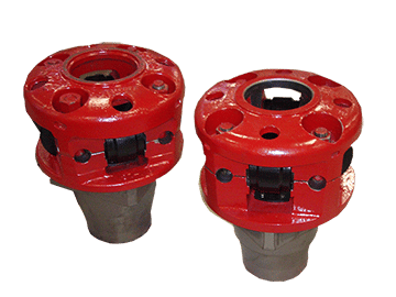
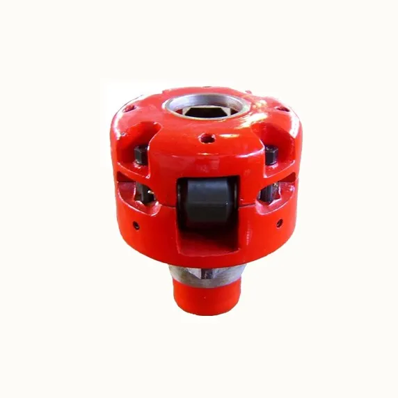
Roller Kelly Bushings can be classed as two types based on different ways of drive, square drive and pin drive. Also they can be classed as three types based on different style, heavy, medium and light-duty. They are used for 17.1/2 to 49.1/2inch rotary tables. They are designed and manufactured according to API Spec 7K.

Mitchell Rotary Rig #21 is the newest and most advanced rig in the Illinois Basin. It has depth capabilities of up to 12,500 feet (3.81 km) total vertical depth (TVD) and full horizontal and directional capabilities.
Rig #21 has a 17 foot (5.2 m) Kelly Bushing Height (KB) and is outfitted with an 800 Bbl steel pit system that is equipped with dual shaker technology as well as 1,000 GPM mud cleaning capabilities. This rig can be outfitted with up to two 1,005 hp triplex pumps with 5,000# fluid ends. Rig #21 has handling equipment for slim hole and regular hole drill strings. It is outfitted with a full stack blowout preventer (BOP) and can also utilize a rotating head if requested.
Mitchell Rotary Rig #21 has the capability to drill the depths required Carbon Capture Sequestration and Enhanced Oil Recovery (CCS-EOR) technologies.

An adapter that serves to connect the rotary table to the kelly. The kelly bushing has an inside diameter profile that matches that of the kelly, usually square or hexagonal. It is connected to the rotary table by four large steel pins that fit into mating holes in the rotary table. The rotary motion from the rotary table is transmitted to the bushing through the pins, and then to the kelly itself through the square or hexagonal flat surfaces between the kelly and the kelly bushing. The kelly then turns the entire drillstring because it is screwed into the top of the drillstring itself. Depth measurements are commonly referenced to the KB, such as 8327 ft KB, meaning 8327 feet below the kelly bushing.

Fred Wilson Drilling Company appeals a final order of the Occupational Safety and Health Review Commission which sustained the administrative law judge"s ("ALJ") findings.1 The ALJ fined the drilling company $250 for violating standard 29 C.F.R. § 1910.36(b)(1) by failing to provide a "Geronimo" escape line for derrickmen working on the "monkey board" platform of its oil drilling rig number nine, and $100 for violating standard 29 C.F.R. § 1910.212(a)(1) by failing to guard the rig"s Kelly bushing and rotary table. We affirm the finding of liability for violation of the first standard; we vacate the second.
The drilling company was found in violation of the standard 29 C.F.R. § 1910.212(a)(1) for failure to guard the Kelly bushing and rotary table. The rotary table, flush with the derrick floor, is approximately three feet in diameter and is constantly rotating during the drilling process. The Kelly bushing rests upon the rotary table surrounding the Kelly, which is a heavy, vertical steel pipe. Power is transmitted from a bank of diesel engines, generators, or power units through a belt system to the rotary table/bushing unit. The rotary table turns the bushing, and together they transmit rotation power to the Kelly while simultaneously permitting vertical movement of the Kelly. The Kelly in turn transmits power to the drill string and cutting bit.
In finding Fred Wilson in violation of this standard, the ALJ acknowledged that use of a Kelly bushing guard would pose serious hazards, but concluded that an unguarded bushing, on balance, presented the more unsafe situation. Because Wilson appeared to have acted under a good faith belief that it might be more hazardous to use such a guard than not to use one, the ALJ reduced the penalty recommended by the Secretary from $250.00 to $100.00.
The ALJ based his finding on the testimony of an OSHA compliance officer whose familiarity with this particular aspect of the drilling industry appears to have been minimal. The inspector had never seen a Kelly bushing guard on any rigs he had inspected, had not visited a factory at which guards were manufactured and had never viewed a Kelly bushing guard other than in brochures published by their manufacturers. The officer admitted that he did not understand how a guard is placed on the rig and that he knew nothing of the maintenance of a Kelly bushing. Finally the officer conceded he did not know what effect a guard would have in the event a "blowout" occurred.
The ALJ also relied on the testimony of the president of the Kelly Bushing Guard Manufacturing Company, who is also the designer of the guard manufactured by his company. Although he had twenty-three years experience as a welder, he was not an engineer, had no formal education beyond the tenth grade, and had not had his guard independently tested. His company, which had been in business for less than a year at the time of the hearing, carried no products liability insurance and had sold only one guard.
Wilson, by contrast, presented the testimony of an oil well drilling expert who was familiar with a variety of Kelly bushing guards, and found that they created hazards by obstructing passageways on the limited space of the rig floor, by confining the drilling operator"s view of the Kelly, and by potentially acting as deflecting shields in the event of a blowout, thereby increasing the likelihood of a fire. Wilson"s Director of Safety and Personnel also testified and stated that the company had investigated the feasibility of using Kelly bushing guards, but had decided against their use because of the additional hazards created. He also testified that the company had no record of any accidents caused by a Kelly bushing in operation without a guard.
The administrative law judge in the case at bar did not, in his finding of fact, indicate that the bushing contained any j-bolts or other protuberances. In both Secretary of Labor v. Grey Wolf Drilling Co., OSHRC Docket No. 77-2328, 1978 (CCH) OSHD P 22,961 and Secretary of Labor v. Grey Wolf Drilling Co., OSHRC No. 77-3803, 1978 (CCH) OSHD P 23,183, the ALJ specifically found that an unguarded Kelly bushing which had no j-bolts or other protuberances constituted less of a hazard than one equipped with a guard. Although the ALJ in Secretary of Labor v. Signal Oilfield Service, Inc., OSHRC Docket No. 77-0226, 1978 (CCH) OSHD P 22,758 upheld the Secretary"s citation for failure to guard the Kelly, the ALJ specifically found that the Kelly bushing had at least four protrusions exposed around its outer perimeter. The court emphasized, however, that its holding did not apply to the new type Kelly bushing installed after the inspection which had a smooth exterior, a caveat noted and approved by the ALJ in the Grey Wolf decisions.
At oral argument in the case at bar, the assertion of Wilson"s counsel that its Kelly bushing was of the same nature and construction as that used in Grey Wolf was unrebutted. While noting that the OSHA compliance officer had testified that the Kelly bushing had protruding bolts, Wilson"s counsel explained that the officer, who, as noted, evinced no real knowledge of the drilling industry, must have been referring to the bevelled and rounded pins which fit into the rotary table. Complainant"s exhibit 10, a picture of the Kelly bushing, supports Wilson"s argument and reveals no j-bolts or other protrusions. Thus, every other administrative law judge that has considered this question has found that, given the present state of development, a Kelly bushing like Wilson"s constitutes more of a hazard guarded than unguarded. We believe the present record requires the same finding.

ROTARY TABLE MASTER BUSHING Filed oct. 22, 1965 4 sheets-sneer 4 BY a@ United States Patent O 3,386,263 ROTARY TABLE MASTER BUSHING Spencer W. Long, Inglewood, Calif., assiguor to Armco Steel Corporation, Middletown, Ohio, a corporation of Ohio Filed Oct. 22, 1965, Ser. No. 501,565 16 Claims. (Cl. 64I-23.5)
ABSTRACT OF THE DISCLOSURE The master bushing assembly for a well drilling rotary machine comprises duplicate split halves each having a laterally extending driving lug provided with a radial driving face, the master bushing halves each lbeing rovi-ded with axially extending pin sockets for reception of driving7 pin-s on a kelly bushing.
This invention relates to well drilling apparatus and is particularly directed to a novel -form of rotary table and bushings for turning the kelly and handling drill pipe.
In -conventional apparatus, the master bushing rests in the rotary table and is provided with a tapered bore to receive wedge-shaped pipe-gripping slips for engaging the outer surface of drill pipe. The master bushing is s-plit axially into two sections to `facilitate removal from the rotary table so that the maximum opening in the rotary table may be used when lowering the bit through the rotary table. The split master bushing is commonly yprovided with a square portion which is received within a square recess in the rotary table, so that the rotary table may turn the master bushing. The kelly drive bushing has been driven by a similar square recess in the master bushing, or by parallel downward extending drive pins. Drive pins on. the kelly bushing are often used when deep drilling operations require a long tapered bore in the master bushing to accommodate long drill pipe slips; in such case the tapered bore extends to the top surface of the master bushing, thereby preventing the use of a drive square in the master bushing.
Heretofore the drive pins on the kelly bushing have been successfully used only with solid master bushings. These solid master bushings have been used to provide accurate spacing for the drive pin sockets and to provide solid support for long drill pipe slips and heavy loads. Solid master bushings have the disadvantage of being awkward to handle, and being time-consuming to remove and replace when large diameter bits, tools, casing, etc. are to be lowered through the rotary table.
The principal object of this invention is to provide a split type master bushing which will remain firmly seated in the rotary table opening and maintain accurate location and spacing of pin sockets for kelly bushing drive pins under forces exerted when d-riving the kelly and which will rigidly support the slips when handling drill pipe. The master Ibushing has a circular shape with external diameters substantially equal to the central openings in the rotary table to provide solid .backing for drill pipe slips, and to maintain the pin drive sockets for the kelly bushing in accurate location. Each master bushing section has a single outward extending driving lug, and the conventional drive square is eliminated. The driving lugs and the sockets for the drive pins of the kelly bushing are so located on the .master bushing sections that the driving forces act to keep the bushing sections seated against the table opening and act to maintain accurate spacing of the drive pin sockets.
FIGURES 6, 7 and 8 are diagrammatic illustrations showing how the driving forces between the table `and the master bushing sections and between the ma-ster bushing sections and the kelly bushing are of .a direction and location to force the master bushing sections outward against the central opening in the rotary table.
FIGURES 9, 10 and 11 show similar force diagrams for a master bushing having a conventional square drive from the rotary table, and kelly bushing drive pin socket locations identical to those of FIGURES 6, 7 and 8.
Referring to the drawings, the rotary machine generally designated 10 includes a stationary base 11 and a rotary ta"ble `12. A bearing Iassembly 13 on the base 11 supports the table 12 for rotary movement. A ring gear 14 xed on the table is driven by a pinion gear 15 xed on a pinion shaft 1-6 rotatably supported on the ibase 11.
The rotary table 12 is provided with a stepped central vertical opening 17 and 17a extending there-through. Drive pockets 18 and 19 are provided in the rotary table 12 at diametrioally opposed positions and each extends to the upper surface 20 of the rotary table. Each pocket yalso extends to the central opening 17. Each of the pockets has -a radial vwall 21, 22.
A master bushing assembly generally designated 24 is split longitudinally to form a pair of duplicate master bushing sections 25 and 26 having confronting faces 27, 28 and 29, 30. The outer 4surfaces 31, 31a of the bushing sections are circular and they are adapted to be received and supported on the shoulder 23 joining the parts of the stepped central opening 17, 17a in the rotary table 12.
Each bushing section has a single driving lug 32, 33, extending outward beyond the outer surface of the bushing section and received in one of the drive pockets 18, 19. The driving lug 32 extends into pocket 18 between the radial wall 21 and the clearance wall 21a spaced therefrom, and is -provided with a radial face 34 for engagement with the radial wall 21 of the pocket 18. Similarly, the driving lug 33 extends into the pocket 19 between the radial wall 22 and the clearance wall 22a spaced therefrom, and has a radial face 35 which contacts the radial wall 22 of the pocket 19. When the parts are in the position shown in the drawings, the radial faces 34 and 35 of the driving lugs 32 and 33, the radial walls 21 and 22 of the table pockets 18 and 19, the radial face 27 of the bushing section 25 and radial face 30 of the bushing section 26 all lie in Vthe same vertical plane which passes through the rotary axis of the rotary table 12. The surface 29 on the bushing section 25 and the surface 28 on the bushing section 26 lie on opposite sides of this common plane and have a small clearance space therewith, which clearance space facilitates installation and removal of the bushing sections with respect to the rotary table 12.
The master bushing sections 25 and 26 cooperate to define a central tapered bore 37 for reception of wedgeshaped pipe-engaging slips, not shown. The central bore 37 extends to the upper surface of the master bushing and its taper portion is relatively long in order to accommodate the long slips employed for gripping heavy strings of pipe. A kelly bushing generally designated 39 is provided with a pilot skirt 40 which extends into the bore 37. The kelly bushing 39 rests on the upper surface of the master bushing 24 and is provided with rollers 41 which engage the faces of the kelly 38. The kelly bushing 39 is provided with four equally spaced downward extending parallel drive pins 42, and these drive pins are received in upward opening sockets 43, 44, 45, 46 provided on the master bushing 24. The pin sockets 43 and 44 are located on the bushing section 25 and the pin sockets 45 and 46 are located on the bushing section 26. Driving torque transmitted by the pinion 15 to the ring gear 14 causes the rotary `table 12 to drive the lugs 32 and 33 on the master bushing sections and these in turn drive the kelly bushing 39 through the drive pins 42. The rollers 41 apply driving torque to turn the kelly 38 while at the same time permitting it to move freely in a vertical direction.
The locations of the pin sockets 43, 44, 45 and 46 on the master bushing sections 25 and 26 are not symmetrical with respect to each bushing section but on the contrary the pin socket 43 is located close to the surface 29 on the bushing section 25, and the pin socket 45 is located close to the surface 28 on the bushing section 26. The pin socket 43 on the bushing section 25 is remote from the driving lug 32 on that same bushing section. Similarly, Vthe pin socket 45 on the bushing section 26 is remote from the driving lug 33 on the same bushing section. Pin socket 44 is located 90 degrees from pin socket 43, and similarly, pin socket 46 is located 90 degrees from pin socket 45.
FIGURES 6, 7 and 8 are force diagrams showing how this arrangement of drive lugs and sockets results in holding the master sections in solid engagement with the rotary table opening 17 under the driving forces imparted by the rotary table to the master bushing sections and by the master bushing sections to the kelly bushing 39. In FIGURE 6 the force P represents the driving force applied by the rotary table 12 to the driving lug 32 on the master bushing section 25. The force Q represents the driving reaction from a kelly drive pin 42 in the socket 44, assuming that all force between kelly bushing 39 and master bushing section 25 is taken by this particular socket. The force R is the reaction of the rotary table 12 against the master bushing section 25, resulting from the yforces P and Q. In FIGURE 7, force P is the same but the forces Q1 and Q2 assume that the sockets 44 and 43 are equally loaded. The force R1 represents the reaction of the rotary table 12 against the master bushing section 25 resulting from the forces P, Q1 and Q2. In FIGURE 8, the force P is the sarne and the force Q represents the driving reaction on the socket 43, assuming that this socket carries all of the force between kelly bushing 39 and master bushing section 25. The force R2 is the reaction of the rotary table 12 against the master bushing section 25 resulting from the forces P and Q. In all three views, FIGURES 6, 7 and 8, it is apparent that the reaction forces R, R1, Rzof the rotary table 12 against the master bushing section 25 are toward the axis of rotation and not away from it. In other words, the driving forces from the rotary table 12 and the driving reactions from the kelly bushing 39 are of a direction and location to force the master bushing section 25 outward against the circular bore in the rotary table 12. Since the bushing section 26 is a duplicate of the bushing section 25, the same forces and reactions occur and both bushing sections are held in solid engagement with the bore of the rotary table by reason of the driving forces and reactions. Although the force diagrams of FIGURES 6, 7 and 8 do not take into account the action of centrifugal force, such centrifugal force serves to supplement the action of maintaining the split master bushing sections 25 and 26 in contact with the circular opening in the rotary table 12.
The force diagrams of FIGURES 9, 10 and 11 show the distribution of driving forces on a split master bushing construction having conventional square driving faces and kelly bushing drive pin socket locations identical to those of FIGURES 6, 7 and 8. The conventional rotary table 12a has a square recess 50 in its upper surface and this recess has parallel faces 51 and 52 and parallel faces 53 and 54. The corners of the square are beveled olf to provide clearance spaces 55. The split master bushing sections 56 and 57 have a conventional square shape with the corners beveled away. In this construction, location of the pin sockets 43a and 44a in the same relative position as that shown in FIGURES 6, 7 and 8 does not result in holding the master bushing sections in solid engagement with the rotary table 12a in all cases. In FIGURE 9, it is assumed that all of the driving reaction -is taken by the socket 44a. This compares to FIGURE 6. In FIG- URE 10, it is assumed that half of the total driving reaction is taken by each socket 43a and 44a. This compares to FIGURE 7. In FIGURE 11, it is assumed that all of the driving reaction is taken by the socket 43a. In FIGURE 9 the driving force P1 would have to be equal to and colinear with driving reaction Q to prevent inward displacement of master bushing section 56 relative to rotary table 12a. Since angle A is much greater than the angle of friction for the contacting surfaces of master bushing section 56 and rotary table 12a, driving force P1 cannot be colinear with driving reaction Q. Hence in FIGURE 9 inward displacement of master bushing section 56 relative to rotary table 12a is not prevented. Since both centrifugal force on master bushing section 56 and driving reaction Q are variable, alternate inward and outward displacement of master bushing section 56 relative to rotary table 12a would occur, thereby causing misalignment and producing excessive wear. Inspection of the force diagram of FIGURE 10 reveals that a similar though not so pronounced tendency toward inward displacement of master bushing section 56 relative to rotary ta"ble 12a exists. No such tendency exists when all of the driving reaction between master bushing section 56 and kelly bushing 39 is taken by socket 43a as shown in FIGURE 11.
Due to manufacturing inaccuracies and wear of parts, the direction and location of the resultant forces will vary between the extremes shown in FIGURES 6, 7 and 8 for the device embodying this invention, and will vary between the extremes shown in FIGURES 9, 10 and 11 for the conventional square drive with kelly bushing drive pin sockets located as shown. With the split circular master bushing shown in FIGURES 6, 7 and 8, the driving forces and centrifugal force will always tend to hold the bushing sections outward against the opening in the rotary table, but with the construction shown in FIG- URES 9, 10 and l1, alternate inward and outward displacement of the master bushing sections 56 and 57 occurs within the rotary table drive recess 50.
From a consideration of the force diagrams of FIG- URES 6, 7, and 8, it is apparent that the maximum benets in maintaining each master bushing section in contact with the rotary table opening is achieved when the pin drive socket remote from the driving lug on that section is positioned as close as practicable to the confronting faces of the master bushing sections.
The sections 25 and 26 of the master bushing 24 may be removed separately from .the opening 17 in the rotary table 12, after the kelly bushing 39 and kelly 38 have been removed. As shown in FIGURE 2, openings 59 are provided in the upper surface of each master bushing section, and a pair of hooks on a sling (not shown) may be inserted into these openings. The location of the openings 59 is chosen so that tilting movement of each bushing is minimized when it is lifted by hooks inserted into these openings.
In order to facilitate installation and removal of the master bushing sections 25 and 26 with respect to the vrotary table 12, the outer wall 61 of each bushing section, which wall is otherwise circular, is provided with a straight portion 62 at a location remote from the driving lug on that bushing section. A clearance space 63 is thus formed between the short straight portion 62 and the circular opening 17 in the rotary table 12. This clearance space 63 insures that adequate clearance develops/ between the circular opening 17 and the outer circular wall 61 of the bushing section when the bushing section swings through a small arc around the corner 64 at the intersection of the opening 17 and the radial face of the driving lug.
Means are provided for releasably latching the master bushing sections 2S and 26 against upward movement relative to the rotary table 12. As shown in FIGURE 3, this means includes a latch actuating pin 66 mounted to turn and slide vertically within aligned openings 67 and 68 on the bushing section 26. The latch pin 66 has an integral enlarged head 69 of non-circular outline and resting in the non-circular recess 70 provided in the upper surface of the bushing section. The pin 66 is slidably keyed to the latch element 71 which has a projecting portion 72 adapted to enter the latch recess 73 provided on the rotary table 12. When the latch is to be operated, the enlarged head 69 is grasped manually, lifted upward out of the recess 70, and then turned one-quarter turn. This moves the projecting portion 72 of the latch element 71 into or out of the latch recess 73. The head 69 is then allowed to descend by gravity back into the non-circular recess 70 to hold the latch element 71 in selected position. A weld bead 74 is provided to limit upward travel of the head 69 and latch pin 66.
In a modified form of the invention shown in FIGURES 12-15, the rotary table and the outer shape of the master bushing sections and the location of the pin drive sockets is the same as that previously described, but a split liner is provided within the central tapered bore dened by the master bushing sections. The master bushing sections are shown at 25a and 26a and each is provided with a single outward extending driving lug 32a and 33a as previously described. Split liner sections 75 and 76 are duplicates and are mounted within the central tapered bore 37a defined by the master bushing sections 25a and 26a. A positioning lug 77 on each liner section and a mating recess 78 on each master bushing section as shown in FIGURE l5 insures that the confronting faces 79 on the liner sections will always be perpendicular to the confronting faces 80 on the master bushing sections, This insures that both liner sections 75 and 76 must be removed from rotary table 12 before removing either master bushing section 25a or 26a, and thus any possibility of accidentally dropping the liner section down through the rotary table is eliminated.
When the liner sections 75 and 76 are removed, the tapered bore 37a in the master bushing sections may be employed with slips for handling large diameter pipe. A pair of hook receiving openings 81 are provided on each liner section to facilitate lifting it from the tapered bore in the master bushing sections. Also latch means are provided for latching the liner sections against upward movement relative to the master bushing sections. As shown in FIGURE 14, the latch element 71a is slidably keyed on the latch pin 66a so that when the latter is raised and turned by means of the enlarged head 69a the projecting portion 72a is swung into or out of the latch recess 73a.
rotary table having a central circular opening and having a pair of diametrically positioned pockets, each pocket having a radial wall and a clearance wall spaced .therefrom, a master bushing assembly having an outer circular surface mounted in said table opening, said master bushing assembly being split axially to forma pair of bushing sections having spaced confronting surfaces, each bushing section having a driving lug adjacent its confronting surface and extending outward beyond said surface into one of said pockets, respectively, and between the radial wall and clearance wall thereof, each of said lugs having a radial driving face engageable with one of said radial walls, respectively, and having another face spaced from one of said clearance walls, respectively.
2. In a well drilling device, the combination of: a rotary table having a central circular opening and having an upper surface provided with a pair of pockets diametrically positioned and extending into said opening, each pocket having a radial wall and a clearance wall spaced therefrom, a master bushing assembly having an outer circular surface mounted in said table opening, said master bushing assembly being split -axially to form a pair of duplicate bushing sections having spaced confronting surfaces, each bushing section having a driving lug adjacent its confronting surface and extending outward beyond said outer surface into one of said pockets, respectively, and between the radial wall and clearance wall thereof, each of said lugs having a radial driving face engageable with one of said radial walls, respectively, and having another face spaced from one of said clearance walls, respectively.
3. In a well drilling device, the combination of: a rotary table having a central circular opening and having a pair of diametrically positioned pockets, a master bushing assembly having an outer circular surface mounted in said table opening, said master bushing assembly being split axially by parallel offset plane surfaces to form a pair of duplicate bushing sections with clearance between said plane surfaces, each bushing section having a driving lug extending outward beyond said outer surface into one of said pockets, respectively, each of said lugs having a radial driving face forming a continuation of one of said plane surfaces.
4. In a well drilling device, the combination of: -a rotary table having a central circular opening and having an upper surface provided with a pair of pockets diametrically positioned and extending to said opening, each pocket having a radial wall, a master bushing assembly having an outer circular surface mounted in said table opening, said master bushing assembly being split axially by parallel offset plane surfaces to form a pair of duplicate bushing sections with clearance between said plane surfaces, each bushing section having a driving lug extending outward beyond said outer surface into one of said pockets, respectively, each of said lugs having a radial driving face forming a continuation of one of said plane surfaces and engageable with one of said radial walls, respectively.
5. In a well drillin-g device, the combination of: a rotary table having a central circular opening and having a pair of diametrically positioned pockets, each pocket having a radial wall, a master bushing assembly having an outer circular surface mounted in said table opening, said master bushing assembly being split axially to form a pair of duplicate bushing sections with confronting surfaces, each bushing section having a driving lug extending outward beyond said outer surface into one of said pockets, respectively, each of said lugs having a radial driving face engageable with one of said radial walls, respectively, the outer circular surface of each master bushing section being relieved at a location adjacent a confronting surface and remote from the lug on that master bushing section, whereby clearance spaces are formed within the circular opening of the rotary table to facilitate removal of the master bushing sections from the rotary table opening.
rotary table having a central circular opening and having a pair of diametrically positioned pockets, each pocket having a radial wall, a master bushing assembly having an outer circular surface mounted in said table opening and having a central bore, said master bushing assembly being split axially to form a pair of duplicate bushing sections with confronting surfaces, each bushin-g section having a driving lug extending outward beyond said outer surface into one of said pockets, respectively, each of said lugs having a radial driving face engageable with one of said radial walls, respectively, a liner having a taper bore and mounted in the central bore of the master bushing assembly, the liner being split axially to form duplicate liner sections with confronting surfaces, and interengaging means on the liner and master bushing sections acting to maintain the confronting surfaces of the liner at right angles to the confronting surfaces on the master bushing sections.
7. For use with a well drilling rotary table, having a central circular opening, the combination of: a master bushing assembly having a circular outer surface for reception in the circular opening o-f the table, said master bushing assembly being split axially by parallel offset plane surfaces to form a pair of duplicate bushing sections with clearance between said plane surfaces, each bushing section having a driving lug extending outward beyond said outer circular surface and having a radial driving face forming a continuation of one of said plane surfaces.
8. For use with a well drilling rotary table having a central circular opening, the combination of: a master bushing assembly having a circular outer surface for reception in the circular table opening, said master brushing assembly being split axially to form a pair of duplicate bushing sections having confronting surfaces, each bushing section having a driving lug extending out-ward beyond said outer circular surface and having a radial driving face forming a continuation of one of the confronting surfaces, the outer circular sur-face of each master bushing section being relieved at a location adjacent a confronting surface and remote from the lug on that master bushing section, whereby clearance spaces are formed within the circular opening of the rotary table to facilitate removal of the master bushing sections from the rotary table opening.
9. For use with a well drilling rotary table having a central circular opening, the combination of: a master bushing assembly having an outer surface for reception in the table opening and having a central bore, said master bushing assembly bein-g split axially to lform a pair of duplicate bushing sections, each bushing section having a drivin-g lug extending outward beyond said outer surface and having a radial driving face adjacent one of the confronting surfaces, a liner having a taper bore and mounted in the central bore of the master bushing assembly, the liner` being split axially to `form duplicate liner sections with confronting surfaces, and interengaging means on the liner and master bushing sections acting to maintain the confronting surfaces of the liner at right angles to the confronting surfaces on the master bushing sections.
10. In a well drilling device, the combination of: a rotary table having a central circular opening, a master bushing assembly having an outer circular surface mounted in said table opening, said master bushing assembly being split axially to form a pair of bushing sections, means for driving each master bushing section from said table, a kelly bushing having four parallel downward extending equally spaced driving pins, said master bushing sections each having two pin sockets for reception of said driving pins, one of said pin sockets on each bushing section lying substantially closer than the other pin socket to the other bushing section.
11. In a well drilling device, the combination of: a rotary table having a central circular opening, a master bushing assembly having an outer circular surface mounted in said table opening, said master bushing assembly being split axially to form a pair of duplicate bushing sections having confronting surfaces, means for driving each bushing section from said table, a kelly bushing having four parallel downward extending equally spaced driving pins, said master bushing sections each having two pin sockets for reception of said driving pins, one of said pin sockets on each bushing section lying substantially closer than the other pin socket to said confronting surfaces.
12. In a `well drilling device, the combination of: a rotary table having a central circular opening and having a pair of diametrically positioned pockets, a master bushing assembly having an outer circular sur-face mounted in said table opening, said master bushing assembly being split axially to form a pair of duplicate bushing sections having confronting surfaces, each bushing section having a driving lug extending outward beyond said outer surface into one of said pockets, respectively, a kelly bushing having four parallel downward extending equally spaced driving pins, said master bushing sections each havin-g two pin sockets for reception of said driving pins, one of said pin sockets on each bushing section lying substantially closer than the other pin socket to said confronting surfaces.
rotary table having a central circular opening and having an upper surface provided with a pair of pockets diametrically positioned and extending to said opening, each pocket having a radial wall, a master bushing assembly having an outer circular surface mounted in said table opening, said master bushing assembly being split axially to form a pair of duplicate bushing sections having confronting surfaces, each bushing section having a driving lug extending outward beyond said outer surface into one of said pockets, respectively, each lug having a radial driving face engaging one of said radial walls, respectively, a kelly bushing having four parallel downward extending equally spaced driving pins, said master bushing sections cach having two pin sockets -for reception of said driving pins, one of said pin sockets on each bushing section being positioned adjacent to said confronting surfaces, and the other pin socket on each bushing section being remote from said confronting surfaces.
14. For use with a well drilling rotary table having a circular central opening, the combination of: a master bushing assembly adapted for reception in the table opening, said master bushing assembly having an upper sur- -face provided with four equally spaced upward opening parallel pin sockets, said master bushing assembly being split axially to form a pair of bushing sections, each with two of said pin sockets, one of said pin sockets on each master bushing section lying substantially closer than the other pin socket to the other bushing section, and each master bushing section having means whereby it may be driven from the rotary table.
15. For use with a well drilling rotary table having a circular central opening, the combination of: a master bushing assembly adapted for reception in the table opening, said master bushing assembly having an -upper surface provided with four equally spaced Iupward opening pin sockets, said master bushing assembly being split axially to form a pair of duplicate bushing sections having confronting surfaces, each master bushing section having two of said pin sockets, one of said pin sockets on each master bushing section lying substantially closer than the other pin socket to said confronting surfaces, and each master bushing section having means whereby it may be driven from said rotary table.
16. For use with a well drilling rotary table having a circular central opening, the combination of: a master bushing assembly adapted for reception in the table opening, said master bushing assembly having an upper surface provided with four equally spaced upward opening pin sockets, said master bushing assembly being split axially to form a pair of duplicate bushing sections having confronting surfaces, each bushin-g section having an outward extending driving lug adjacent said confronting surfaces whereby the bushing section may be driven from 1,892,690 1/ 1933 Witkin 64-23.5 the rotary table, each master bushing section having two 1,976,057 10/ 1934 Zilen 64-23.7 of said pin sockets, one of said pin sockets on each bush- 2,075,028 3/ 1937 Driscoll 64-23.5 ing section lying remote =from the driving lug and sub- 2,183,012 12/ 1939 Davidson 64-23.5 stantially closer than the other pin socket to said con- 5 2,204,645 6/ 1940 Baash 64-23.5 fronting surfaces. 2,306,130 12/1942 Long 64-23.7 2,344,746 3/ 1944 Spalding 64-23.5
The global kelly drive market was valued at $1.6 billion in 2021, and is projected to reach $2.3 billion by 2031, growing at a CAGR of 3.7% from 2022 to 2031.
Report Key HighlightersThe kelly drive market is consolidated in nature with few players such as NOV Inc., SANY Group, BAUER Maschinen GmbH (Subsidiary of BAUER Group), Jereh Global Development LLC (As a Subsidiary of Jareh Group) and Liebherr-International Deutschland GmbH. that hold significant share of the market.
The study covers in-depth analysis of 16 countries from different regions including North America, Europe, Asia-Pacific, and LAMEA. In addition, country-wise data of every country has been provided for better understanding of kelly drive market dynamics in every country.
A kelly drive is a particular kind of well drilling tool which uses a section of pipe with a polygonal or splined outer surface and feeds it through a rotary table and matching kelly (mating) bushing which have the same shape or splines. The Kelly is a long, four- or six-sided steel bar having a hole bored through the center to allow drilling fluid to pass through. The kelly bushing allows the drill string to be lifted or lowered while it rotates by transferring rotating motion fro


 8613371530291