
rotary kelly bushing free sample

A kelly drive is a type of well drilling device on an oil or gas drilling rig that employs a section of pipe with a polygonal (three-, four-, six-, or eight-sided) or splined outer surface, which passes through the matching polygonal or splined kelly (mating) bushing and rotary table. This bushing is rotated via the rotary table and thus the pipe and the attached drill string turn while the polygonal pipe is free to slide vertically in the bushing as the bit digs the well deeper. When drilling, the drill bit is attached at the end of the drill string and thus the kelly drive provides the means to turn the bit (assuming that a downhole motor is not being used).
The kelly is the polygonal tubing and the kelly bushing is the mechanical device that turns the kelly when rotated by the rotary table. Together they are referred to as a kelly drive. The upper end of the kelly is screwed into the swivel, using a left-hand thread to preclude loosening from the right-hand torque applied below. The kelly typically is about 10 ft (3 m) longer than the drill pipe segments, thus leaving a portion of newly drilled hole open below the bit after a new length of pipe has been added ("making a connection") and the drill string has been lowered until the kelly bushing engages again in the rotary table.
The kelly hose is the flexible, high-pressure hose connected from the standpipe to a gooseneck pipe on a swivel above the kelly and allows the free vertical movement of the kelly while facilitating the flow of the drilling fluid down the drill string. It generally is of steel-reinforced rubber construction but also assemblies of Chiksan steel pipe and swivels are used.
The kelly is below the swivel. It is a pipe with either four or six flat sides. A rotary bushing fits around the flat sides to provide the torque needed to turn the kelly and the drill string. Rollers in the bushing permit the kelly free movement vertically while rotating. Since kelly threads would be difficult to replace, normally the lower end of the kelly has saver sub — or a short piece of pipe — that can be refurbished more cheaply than the kelly. Usually, a ball valve, called the lower kelly cock, is positioned between the kelly and the kelly saver sub. This valve is used for well control if the surface pressure becomes too high for the rotary hose or surface conditions.
According to the ″Dictionary of Petroleum Exploration, Drilling and Production″, ″[The] kelly was named after Michael J. (King) Kelly, a Chicago baseball player (1880-1887) who was known for his base running and long slides.″

Because wells are not always drilled vertically, there may be two "depths" for every given point in a wellbore: the borehole, and the datum and the point in the wellbore. In perfectly vertical wells, the TVD equals the MD; otherwise, the TVD is less than the MD measured from the same datum. Common datums used are ground level (GL), drilling rig floor (DF), Rotary table (RT), kelly bushing (KB or RKB) and mean sea level (MSL).
Example: the top of a reservoir may be found at 1,500 mMDRT in a particular well (1,500 m measured depth below the rotary table), which may be equal to 1,492 mTVDMSL (1,492 m true-vertical-depth below mean sea level) after correction for deviations from vertical.
The acronym TVDSS is commonly used in the oil industry to represent TVD minus the elevation above mean sea level of the depth reference point of the well. The depth reference point is the kelly bushing in the United States and a few other nations, but is the drill floor in most places.
Petrophysicists and drilling operations tend to express depths with reference to the rotary table or the original drill floor; geologists tend to use a common datum such as the mean sea level; geophysicists use the mean sea level. This can introduce much confusion when a unit is not specified with all 3 components: unit, path, and reference.
Common references used in operations include: Rotary Table (RT), Drill Floor (DF), Kelly Bushing (KB), Sea Bottom (SB), Ground Level (GL), Casing Bowl Flange (CBF).
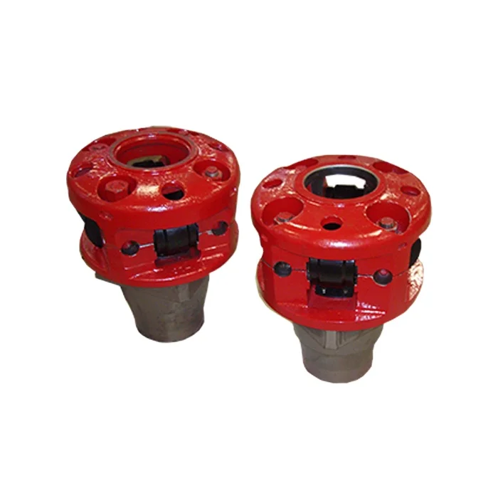
Kelly bushing is that elevated device positioned right on top of the rotary table and used to transmit torque from the rotary table to the kelly. The kelly bushing is designed to be the connection between the rotary table and the kelly. The kelly is a 4 or 6 sided steel pipe.
The purpose of the rotary table is to generate the rotary action (torque) and power necessary to rotate the drillstring and drill a well. The torque generated by the rotary table is useless if it is not transferred to the kelly (the drillstring is connected to the kelly).
Hence, through the kelly bushing the torque generated at the rotary table is transferred to the kelly. To achieve this connection, the inside profile of the kelly bushing matches the outer profile of the kelly so that the kelly fits or “sits” comfortably in the kelly bushing.
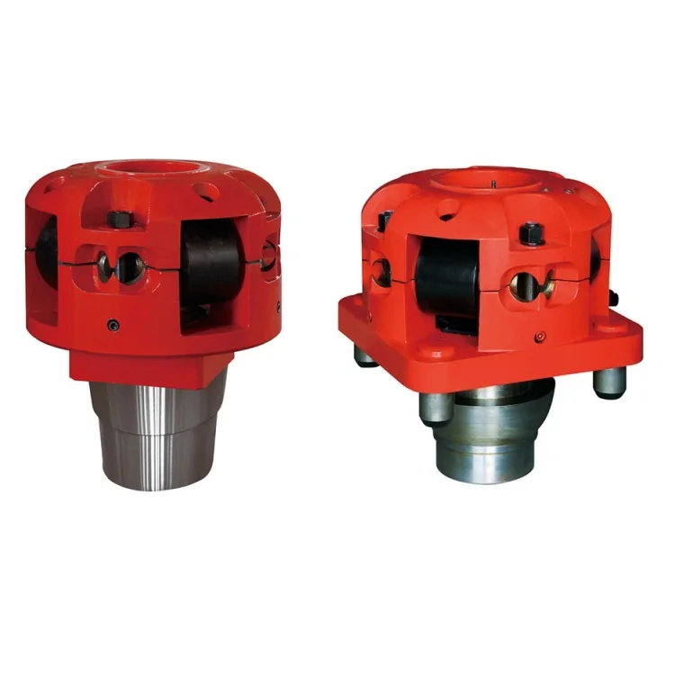
There are various designs for the kelly bushing including the split type, the pin-drive type and the square-drive type. Each of these designs has different ways in which they are connected and disconnected from the rotary table.
The internal diameter of the kelly bushing can be cut into the shape of a square (4-sided) or a hexagon (6-sided) depending on the outer shape of the kelly that will be used. The internals of a Kelly bushing is designed to resemble the outer shape of a Kelly just like the insides of a key lock is cut to exactly match the outer shape of the key.
The kelly bushing is not designed to hold tightly onto the Kelly; the kelly is still permitted to move up and down through the kelly bushing. This requirement is a must since drilling cannot progress if the kelly remains on a fixed spot. As the well is drilled deeper, the kelly also moves downward through the Kelly bushing.
The kelly bushing is sometimes used as a reference point from which depth measurements can be taken. All depths must be recorded with respect to a reference point; the kelly bushing (KB) is one of the depth references used in the oil and gas industry.
The top of the kelly bushing is normally used as the depth reference.For example, 7500ft KB means 7500ft below the kelly bushing or 7500ft measured from the top of the kelly bushing down to that point in the well.
In some other cases, depths could be recorded as 7500ft MDBKB meaning 7500ft measured depth below the kelly bushing. This is mostly used when the measured depth is different from the true vertical depth of the well, common with deviated and horizontal wells.

The square or hexagonal shaped steel pipe connecting the swivel to the drill string. The kelly moves through the rotary table and transmits torque to the drill string.
Square- or hexagonal-shaped steel pipe connecting the swivel to the drill pipe. NOTE The kelly moves through the rotary table and transmits torque to the drill stem.
Square or hexagonally shaped steel pipe connecting the swivel to the drill pipe that moves through the rotary table and transmits torque to the drill stem.
The square, hexagonal or other shaped steel pipe connecting the swivel to the drill pipe. The kelly moves through the kelly bushings, rotary table and rotates the drill string.
The uppermost component of the drill string; the kelly is an extra-heavy joint of pipe with flat or fluted sides that is free to move vertically through a “kelly bushing” in the rotary table; the kelly bushing imparts torque to the kelly and thereby the drill string is rotated.
The uppermost component of the drill string; the kelly is an extra-heavy joint of pipe with flat or fluted sides that is free to move vertically through a “kelly bushing” in the rotary table; the kelly bushing imparts torque to the kelly and thereby the drill string is rotated.
“Kelly” means a 3 or more sided shaped steel pipe connecting the swivel to the drill pipe. The kelly moves through the kelly bushing and the rotary table and transmits torque to the drill string. [Mich. Admin. Code R 408 (2013)].
The square or other shaped steel pipe connecting the swivel to the drill pipe. The kelly moves through the rotary table and transmits torque to the drill string.

The cutting or boring element used in drilling oil and gas wells. Most bits used in rotary drilling are roller-cone bits. The bit consists of the cutting elements and the circulating element. The circulating element permits the passage of drilling fluid and uses the hydraulic force of the fluid stream to improve drilling rates.†
The heavy square or hexagonal steel member suspended from the swivel through the rotary table. It is connected to the topmost joint of drill pipe to turn the drill stem as the rotary table turns.†
A device fitted to the rotary table through which the kelly passes. It is the means by which the torque of the rotary table is transmitted to the kelly and to the drill stem. Also called the drive bushing.†
A hole in the rig floor 30 to 35 feet deep, lined with casing that projects above the floor. The kelly is placed in the rathole when hoisting operations are in progress.†
The hose on a rotary drilling rig that conducts the drilling fluid from the mud pump and standpipe to the swivel and kelly; also called the mud hose or the kelly hose.†
The principal component of a rotary, or rotary machine, used to turn the drill stem and support the drilling assembly. It has a beveled gear arrangement to create the rotational motion and an opening into which bushings are fitted to drive and support the drilling assembly.
A series of trays with sieves or screens that vibrate to remove cuttings from circulating fluid in rotary drilling operations. The size of the openings in the sieve is selected to match the size of the solids in the drilling fluid and the anticipated size of cuttings. Also called a shaker.†
Wedge-shaped pieces of metal with teeth or other gripping elements that are used to prevent pipe from slipping down into the hole or to hold pipe in place. Rotary slips fit around the drill pipe and wedge against the master bushing to support the pipe. Power slips are pneumatically or hydraulically actuated devices that allow the crew to dispense with the manual handling of slips when making a connection. Packers and other down hole equipment are secured in position by slips that engage the pipe by action directed at the surface.†
A relatively short length of chain attached to the tong pull chain on the manual tongs used to make up drill pipe. The spinning chain is attached to the pull chain so that a crew member can wrap the spinning chain several times around the tool joint box of a joint of drill pipe suspended in the rotary table. After crew members stab the pin of another tool joint into the box end, one of them then grasps the end of the spinning chain and with a rapid upward motion of the wrist "throws the spinning chain"-that is, causes it to unwrap from the box and coil upward onto the body of the joint stabbed into the box. The driller then actuates the makeup cathead to pull the chain off of the pipe body, which causes the pipe to spin and thus the pin threads to spin into the box.†
A vertical pipe rising along the side of the derrick or mast. It joins the discharge line leading from the mud pump to the rotary hose and through which mud is pumped going into the hole.†
A rotary tool that is hung from the rotary hook and traveling block to suspend and permit free rotation of the drill stem. It also provides a connection for the rotary hose and a passageway for the flow of drilling fluid into the drill stem.†
The large wrenches used for turning when making up or breaking out drill pipe, casing, tubing, or other pipe; variously called casing tongs, rotary tongs, and so forth according to the specific use. Power tongs are pneumatically or hydraulically operated tools that spin the pipe up and, in some instances, apply the final makeup torque.†
The top drive rotates the drill string end bit without the use of a kelly and rotary table. The top drive is operated from a control console on the rig floor.†
Rotary drilling rigs for forming boreholes require a rotary table centrally positioned on the floor of the drilling rig. The rotary table has a rotating center which receives a kelly bushing therein which imparts rotation into a kelly. The kelly is free to slide within the bushing and has a string of drill pipe connected at the lower end and a swivel at the upper end thereof.
The rotating table center and kelly bushing usually have bolt heads, fastener heads, and various other protrusions as well as various different indentions formed thereon. This is especially so on the older rotary drilling rigs.
Accordingly, it is advantageous and highly desirable to encapsulate the rotary table of a drilling rig so as to isolate this dangerous area from the workmen so that should one accidently drop anything on the rig floor, it cannot possibly be caught in the rotating center.
This invention relates to drilling rig safety equipment, and specifically to a guard for a rotary table and a kelly, such as may be found on a rotary drilling rig or a workover unit. The guard of this invention has a lower end in the form of a flat circular show member from which there upwardly extends a wall member. The upper end of the wall member terminates at a bearing means. The bearing means is spaced from and concentrically arranged respective to the shoe, and has a rotatable part which slidably receives a marginal length of the kelly therethrough. The rotating kelly rotates the rotatable part of the bearing while the remainder of the bearing means remains stationary. Hence, the guard encapsulates the most dangerous parts of the rotary table and kelly and prevents extraneous items from falling into contact therewith.
Another object of the present invention is to provide apparatus which will prevent extraneous members from contacting the rotating parts associated with a rotary table of a drilling rig or the like.
Another and still further object of this invention is to disclose and provide a safety structure which prevents contact of anything with the dangerous rotating parts of a rotary table.
A still further object of this invention is to provide a guard in the form of a non-rotating safety shield located about the rotating parts of a rotary table so that nothing can inadvertently contact the rotating parts.
This invention relates to a rotary table and kelly bushing guard for use in conjunction with a drilling rig, workover rig, or the like. In drilling boreholes, the massive rotary table, kelly, and kelly bushing are exposed in the center of the greatest activity of the drilling operation. From time to time, a roughneck will inadvertently catch a hose or chain or the like in the rotating mass, whereupon he often is violently thrown into the apparatus and fatally injured. Accordingly, the apparatus of the present invention isolates this dangerous mechanism from the surrounding area so that extraneous material cannot inadvertently come into contact therewith.
As seen in FIG. 1, a derrick floor 10 of a rotary drilling rig includes the non-rotating, circumferentially extending floor area 12 which overlies a rotary mechanism 14. The mechanism imparts rotation into a kelly bushing 16 by means of a drive sprocket 18 connected to the end of a pinion shaft of the rotary device. The kelly 20 is slidably received in a telescoping manner through the kelly bushing 16 in the usual manner, while drive mechanism 22 removably receives the kelly bushing 16 in the usual manner. As mechanism 16, 20, and 22 rotate respective to the fixed floor 12, there is a danger area 24" which must be avoided. There is always the grave danger that someone will somehow or another slip and fall into the danger area and thereby become severely injured.
In order to obviate this catastrophe, a rotary table and kelly bushing guard 24, made in accordance with the FIGS. 2--11 of the present invention, is slidably received about the kelly 20, thereby encapsulating the dangerous rotating mechanism of the drilling rig. The guard 24 includes an upper member in the form of bearing means 26 which slidably receives the rotating kelly therethrough. A heavy rubber shoe 28 forms a lower support member and is supported by the non-rotating area located outwardly of the rotary table, while a mid-portion 30 in the form of a circumferentially extending wall interconnects the bearing means 26 with the shoe 28.
As seen in FIGS. 6 and 8, together with other figures of the drawing, the bearing means includes Teflon rotatable member 36 within which there is formed an axial passageway 38 which slidably mates and rotates with the kelly 20. Bearing housing 40 is of annular configuration and preferably has the upper marginal end of ribs 32 molded therewithin. Washer 42 is split as indicated at 43 and is removably affixed to the fixed housing 40 by means of a plurality of fasteners 44 so that the rotating member 36 is captured in low friction relationship within the non-rotating member 40. This expedient enables the rotating member 36 to slidably receive and rotate with kelly 20 while non-rotating member 40 is held in a non-rotatable manner respective to the derrick floor and to the mid-portion 30.
Ribs 32 downwardly extend from the fixed upper housing member 40, as indicated by numeral 46. Member 36 is split into portions 48 and 50 so that the spaced fastener means 52 can be utilized for assembling the apparatus onto the kelly. Numeral 54 is the interface formed between the two members. The fasteners are received through apertures 56 and can include self-locking nuts and the like as may be desired.
In operation, fasteners 44 are removed to permit the two halves of washer 42 to be removed from the Teflon bearing assembly located at the upper end of the safety guard 24. Fasteners 52 are removed in order to split the rotating bearing member into halves 48 and 50 thereby facilitating assembly. The halves are placed about the kelly in the illustrated manner of FIG. 2. Stop member 25 preferably is a clamp device smaller in diameter than the pin or threaded male end of the kelly, and is tapered at the lower end to facilitate entrance through the kelly bushing and into the rat hole. The clamp holds the guard in the illustrated position of FIG. 3.
Bearing member 36 slidably engages the kelly for axial movement so that the kelly can continuously move in a downward direction as drilling progresses. When the kelly is lifted from the rotating table, the bearing means 36 of the protector device of the present invention engages the stop 25 and is lifted therewith in the manner of FIG. 3 so that another joint of drill pipe can be added to the drill string.
Hence, the rotating Teflon bearing axially slides respective to the kelly and captures the kelly therewithin so that it is rotated therewith. The heavy plastic guard cover 30 is nonrotatable and does not turn during kelly operation. The guard cover prevents one from inadvertently falling or stepping onto the rotary table, and furthermore prevents objects such as chains or hoses or ropes from catching the rotary table or kelly, and being wound thereabout, causing possible injury to adjacent personnel.
The heavy rubber shoe is located at the lower end of the safety guard. The shoe is provided with the illustrated small inside diameter 68 which forms a heel and tapers in an outward direction and terminates in a toe at large outside diameter 72. The bottom of the shoe is seen at 70. The marginal lower end of members 32 are imbedded within the shoe as noted by the numeral 74. This configuration forms a low profile so that a roughneck will not inadvertently stump his toe on the shoe. The present invention can be used in conjunction with any type of drilling or workover unit having a rotary table thereon. The non-rotating slidable safety guard of the present invention can be made of plastic, fiberglass, rubber, or metal, as shown in FIGS. 2 and 4. The safety guard can be left on the kelly and need not be removed for extended periods of time.
The center of the rotating bearing 36 can be made square as illustrated or hexagon to accommodate a hex shaped kelly as well as being made in other configurations for accommodating any other type kelly.

This invention pertains to kelly drives used in the rotary method of drilling. More particularly the invention pertains to roller kelly drive bushings adapted to fit in the master bushing of a rotary table such as used in drilling for oil by the rotary method.
Briefly the invention includes a body having a circular base beneath which extends a square pin adapted to be received in the square socket of a rotary table master bushing and above which extend four pairs of posts providing four sets of shaft support holes. The posts of each pair are asymmetrically placed relative to the base diameters. Between each pair of posts is pivotally mounted an H shaped cage with a shaft extending through the cross bar of the H shaped cage into the pair of support holes provided by the posts, the cage cross bar having a bushing where it pivots about the shaft. Each cage carries a pair of rollers rotatably mounted on shafts carried by the opposite ends of the cage, the rollers being provided with bushings to rotate on the shafts. Releasable means is provided to fix each cage and roller shaft against rotation and prevent axial motion thereof. Each cage and roller shaft has an axial grease passage therethrough joining radial passages communicating with the exterior of the shaft within the corresponding bushing. Each bushing is recessed adjacent the ends of the radial passages in the shaft to communicate the grease with the whole periphery of the shaft. Spring pressed ball check valves in the ends of the axial passages through the shafts provide means for introducing grease. Different sizes and shapes of rollers can be used. A lower cylindrical housing is secured to the body on top of the base; an upper housing is releasably connected to the tops of the posts. Ports in the housings permit access to the grease valves for lubricating the shafts and bushings.
The centrally pivoted cage mounted rollers cause the kelly to be driven smoothly without wobbling, whip, vibration, or binding during axial feed, despite misalignment of the rotary table and crown block and despite crookedness of the kelly, while assuring positive drive and adequate dispersal of driving pressure on the kelly. This arises by virtue of the kinematic geometry of the pivot cage mounted rollers whereby the normal tolerances needed to fit any bushing around a kelly allow the caged rollers to align themselves with the kelly despite such misalignment and crookedness. The resulting absence of bending moments in the kelly reduces wear and vibration and prevents binding. The kinematics of the caged rollers makes it impossible for but one of the rollers of each cage to take all of the driving torque, thereby insuring adequate dispersal of driving pressure and avoiding Brinnelling of the kelly.
The ready removal and replacement of the roller cage shafts makes it a simple matter to remove two adjacent cages so that the apparatus can be threaded over the enlarged end of a kelly and the cages replaced prior to use.
The adaptability of the apparatus to use with standard A.P.I. master bushings and the easy removal and replacement of the roller shafts whereby change of rollers to fit difierent sizes and shapes of kellys is facilitated makes the apparatus of wide applicability.
FIGURE 1 is a front elevation of a kelly bushing embodying the invention having rollers therein adapted to engage a square kelly of medium size, the housings being cut away in vertical section to show the interior of the apparatus, and portions of the front cage and lower roller being sectioned to show the lubrication systems therefor;
FIGURE 2 is a plan View of the FIGURE 1 apparatus with both of the housings broken away and one cage broken away partially to show the lower roller, different rollers having been substituted suitable for use with a large size hexagonal kelly;
FIGURE 3 is a perspective of the apparatus of FIG- URE 2 showing the exterior thereof, the apparatus being shown disposed in a rotary table and around a hexagonal kelly, and illustrating the manner of servicing the bearings.
Referring now to FIGURES l and 2, the twoapparatuses being identical except for the rollers, there is shown a body 10 having a circular base portion 11. Beneath the base extends a square pin 12 adapted to fit in the master bushing of a conventional rotary table. The upper portion 13 of the base 11 is of reduced diameter providing a shoulder 14 on which rests a cylindrical lower husing :15. The lower housing is welded to the base at 16.
There is a circular cross section passage 20 through the body adapted to receive a kelly such as hexagonal kelly 21, shown only in FIGURE 2 (and FIGURE 3). There is a counterbore 22 in the lower end of pin 12 adapted to rest on the pin of a support in the rat hole (not shown) when the kelly and kelly bushing are not in use: Preferably passage 20 is slightly flaring downwardly, as shown in FIGURE 1, to facilitate placement thereof over the upper end of a kelly.
Each plate is provided with a hole 50 beneath which is disposed a threaded nut 51 welded to the plate concentrio with the hole. The peripheries of plates 39-42 are of less radial extent than the outer edges of the posts leaving shoulders such as 56., 57 to facilitate placement of an per housing 58. Housing 58 is dome shaped and has an opening 59 through the top thereof through which a kelly may pass. There are four indented portions such as 60, 61 around the upper housing, the lower portions of which are fiat and adapted to rest on top of the plates. There is a hole through each indented portion of the upper housing adapted to receive a screw such as 62, 63 which engages the nuts beneath the plates to hold the housing in position.
Each pair of posts such as 30, 31, provides a pair of aligned support holes such as 70, 71 adapted to receive a shaft such as 72. Each shaft 72 is slightly bevelled at its ends as shown at 73 to facilitate placement in the support holes. An arcuate recess 74 is formed on each end of the shafts 72 to receive the overlapping edge of a retaining washer 76 which holds the shaft against both axial and rotary motion relative to the post. Washer 76 is held in place by socket headed screw 77". To facilitate placement of shaft 72 in support holes 70, 71 and alignment of arcuate recess 74 with washer 76, the ends of the shaft are slotted as shown at 78.
Each shaft 72 has a cage 80 pivotally mounted thereon. Each cage is of H shape with a hole 81 through the cross bar receiving the corresponding shaft 72. The holes 81 are provided with bronze bushing sleeves 82. Within each sleeve 82 is an annular grease reservoir groove 83. Communicating with groove 83 are radial passages 84, 85 in the shaft 72 which connect to axial passage 86 extending from one end of shaft 72 to the other. The ends of passage 86 are counterbored and threaded as shown at 87, 88 to receive check valve fittings 89 adapted to be connected to a conventional grease gun. Referring momentarily to FIGURE 3, four openings 90 spaced around the lower housing 15 provide access to the grease check valve fittings without the necessity of removing the housings.
Returning to FIGURES 1 and 2, when grease is pumped through a check valve 89 it goes through an axial passage 86 and out through radial passages 84, 85 into annular reservoir 83 and thence out between the bushing sleeve 82 and shaft 72, flushing out the old grease ahead of it. The grease escaping at the ends of shaft "72 goes into the space between bosses 90, 91 on the cage and bosses 92, 93 on the posts forming a seal against entrance of dirt, water and other foreign matter to the bearing area between sleeve82 and shaft 72.
Between the pairs of legs 101-102, 101"-102 at the"upper and lower ends of each H-shaped cage 80 are rotatably mounted rollers such as rollers 103, 104, 105", 106" shown in FIGURE 1. The rollers are mounted on shafts such as 107 on which rollers 104 is mounted. Each roller has a bushing sleeve such as 108 in roller 104. Shaft 107 is prevented from turning and moving axially by washers such as 109, 110, similar to the mounting of shaft 72. Shafts 107 and bushing sleeves 108 are provided with axial, radial, and annular grease passages 111, 112, 113 similar to those of shaft 72 and sleeve 82, to which grease is pumped through check valves 114, 115, screwed into counterbores 116, 117 in the ends of the shaft 107. When it is desired to lubricate the rollers, a conventional grease gun is used the same as for the cage.
When the grease in the roller lubrication passages is flushed out, the excess grease exuding between the ends of bushing sleeves 108 and shafts 107 escapes into the space between bosses 140, 141 on the inside of the cage and the adjacent sides of the rollers to form seals against dirt, water and other foreign matter.
Referring particularly to FIGURE 2, there are shown the rollers used to drive a hexagonal kelly. In the cages 80, on the front and back sides of the apparatus there are cylindrical rollers such as 151, 152 in the tops of the cages and like rollers in the bottoms of the cages. In the cages 153, 154 at the sides of the apparatus are disposed pairs of rollers such as upper roller 155 and lower roller 156. Top roller 155 in cage 153 is conical and adapted to engage a side of the kelly adjacent the side engaged by roller 151. The roller in the bottom of cage 153 is similar to roller 156 and is adapted to engage the side of the kelly adjacent to the side engaged by roller 152. Similarly the upper and lower rollers of cage 154 are adapted to engage different sides of the kelly.
It will be noted that the pairs of posts supporting each roller are asymmetrically located with respect to the diameters through the center of the kelly perpendicular to the roller axes, being displaced clockwise, so that when larger diameter rollers are used to drive smaller size kellys, the rollers do not interfere, while at the same time each roller bears at or near the leading corner of the adjacent side of the kelly where it has the maximum torque radius. The posts provide means holding each cage against all rotation about a vertical axis relative to the body 10.
It is because of the asymmetric positioning of the pairs of posts that the two rollers for the side cages are of different shape to engage the two different sides of the kelly. The roller 156, engaging the side of the kelly, has its largest cone diameter at the end of the roller nearest the perpendicular diameter (the diameter through the kelly center and perpendicular to the roller axis). Therefore the largest cone diameter of roller 156 is smaller than that of roller 155 whose largest cone diameter is at the end of the roller farthest from the perpendicular diameter. Because the largest diameter of roller 156 is smaller, it is necessary to discontinue the cone taper after it leaves the kelly and finish off with a cylindrical portion 181. The juncture between the conical and cylindrical portions is provided with a stress relief groove 182.
When larger diameter rollers are substituted to engage a smaller kelly, the cylindrical rollers are bevelled on their ends that are farthest from the perpendicular diameter. This is shown at 191, 192, 193 in FIGURE 1. This provides additional clearance without reducing the area of contact with the kelly which in such case has smaller sides available for contact by the rollers.
In operation of the kelly bushing above described, it is to be noted that if a cage tilts so that one of its rollers is out of contact with the kelly or has less contact pressure than the other, there is created a torque automatically turning the cage about its axis to equalize the pressures of the upper and lower rollers. The same torque also automatically places each cage parallel to the kelly axis instead of placing a bending moment on the kelly to align it with the cage. These are marked advantages over roller kelly bushings having the rollers mounted on fixed axes.
In connection with the alignment of the cages with the kelly, it is to be noted that when the cages turn out of their vertical positions in order to follow a crooked or non-vertical kelly, the distance between the cages is reduced slightly. However with the usual tolerances required to manufacture and assemble the apparatus and to place it over a kelly, the distance between the cages and their rollers is not reduced to a point sufficient to bind on the kelly until the cage has moved far more than the maximum amount needed to accommodate any deviation of the kelly from vertical that is to be expected in practice. The elasticity of the materials increases the amount of angular displacement of the cages possible without binding on the kelly.
The housings around the cages and rollers permit them to operate while the apparatus is rotating with a rotary table without danger to personnel adjacent thereto. The bearings of the cage and rollers are easily serviced Without removing the protecting housings, thereby reducing the likelihood of the housings being left olf or the servicing being omitted.
1. A roller kelly bushing comprising a body having a vertical hole therethrough to receive a kelly, a plurality of pairs of cages, the cages of each pair being disposed on diametrically opposite sides of said hole, means independently pivotally mounting each cage directly on the body for rotation about a horizontal axis perpendicular to a radius from said hole extending through the cage and simultaneously holding the cage against all rotation about a vertical axis relative to said body, each cage having a roller rotatably mounted thereon above the cage pivot axis and another roller rotatably mounted thereon below the cage pivot axis, the position of each of said pairs of cages being unaffected by the rotation of the other of said pairs of cages.
3. A roller kelly bushing comprising a body including a base having a vertical hole therethrough to receive a kelly and four pairs of vertical posts on the upper side of of the base, four shafts disposed with one between each pair of posts with its axis horizontal, said pairs of posts being placed so as to locate said four shafts with the axis of each lying along a different one of the four sides of a rectangle extending around said hole, fou-r cages each independently pivotally mounted on one of said shafts for rotation about the axis thereof, the location of said shafts disposing said cages in two pairs with the cages in each pair on opposite sides of said hole, each cage having a roller rotatably mounted thereon above the cage pivot axis and another roller rotatably mounted thereon below the cage pivot axis, the rollers of one cage of one pair of cages being adapted to engage one side of a kelly and the rollers of the other cage of said one pair being adapted to engage the opposite side of the kelly and said cages of said one pair rotating equal amounts about their shafts in case of misalignment of the kelly, the position of the other of said pairs of cages being unaffected by the rotation about its shafts of said one of said pairs of cages, said posts holding said cages against all rotation about a vertical axis relative to said body and against all rotation about a horizontal axis other than the axis of said shaft.
4. A roller kelly bushing comprising a body including a base having a vertical hole therethrough to receive a kelly and a plurality of pairs of vertical posts on the upper side of the base, a shaft disposed between each pair of posts with its axis horizontal and perpendicular to a radius from the hole, a plurality of cages each pivotally mounted on one of said shafts for rotation about the axis thereof, each cage being of H shape with the bar of the H forming the pivot axis of the cage, eagh cage having a roller rotatably mounted thereon between the upper legs of the H and another roller rotatably mounted thereon between the lower legs of the H.
5. A roller kelly bushing comprising a base having a hole vertically therethrough to receive a kelly and a plurality of cages each pivotally mounted thereon for rotation about a horizontal axis, each cage having a roller rotatably mounted thereon above the cage pivot axis and another roller rotatably mounted thereon below the cage pivot axis, characterized by the fact that there are four pairs of posts, four cages, one cage being mounted between each of the four pairs of posts, the pairs of posts are equally spaced around the top of the base, the rollers on two opposite cages all have cylindrical portions for contacting a kelly, and the other two cages have conical rollers for contacting a kelly, the upper and lower conical rollers in each of the last two said cages tapering in opposite directions.
The kelly is a primary link between the drilling rig’s surface equipment and the bit, and is therefore a critical component of the rotary system. Although top drive systems have replaced kelly/rotary table combinations on many rigs, some knowledge of their manufacture and operation is useful.
Their angled surfaces, or drive flats, are designed to fit into a drive roller assembly on the kelly bushing, so that as the rotary table turns to the right, the kelly turns with it. To allow for normal right-hand rotation of the drill string, kellys have right-hand threads on their bottom connections and left-hand threads on their top connections.
The American Petroleum Institute has established manufacturing and design standards for kellys, and has included them in the follwoing publications:API RP 7G, Recommended Practice for Drill Stem Design and Operating Limits.
For a kelly to be efficient in turning the drill string, the clearance between its drive flat surfaces and the rollers in the kelly bushing must be kept to a minimum. Kellys most often wear out due to a rounding-off of the drive corners, as shown in Figure 1 (new kelly with new drive assembly) and Figure 2 (worn kelly with worn drive assembly).
For minimal rounding, there must be a close fit between the kelly and the roller assembly, with the rollers fitting the largest spot on the kelly flats. Manufacturing techniques and rig operating practices play important roles in determining this fit.
Both square and hexagonal kellys are manufactured either from bars with an “as-forged” drive section, or from bars with fully-machined drive sections. Forged kellys are cheaper to manufacture. But machined kellys tend to last longer because:Unlike forged kellys, machined kellys are not subject to the metallurgical process of decarburization, which leaves a relatively soft layer of material on the drive surface that can accelerate the rounding process and increase the potential for fatigue cracks;
To minimize rounding, rig personnel should follow these guidelines (Brinegar, 1977):Always use new drive-bushing roller assemblies to break in a new kelly.
Frequently inspect and periodically replace drive assemblies to ensure that clearance and contact angle between the kelly and the rollers is held to a minimum;
Fatigue failures are seldom a problem with kellys because of the high-quality steels used in their manufacture. Nevertheless, kellys should be regularly inspected for cracks and other signs of wear, particularly within the threaded connections, in the areas where the flats join the upper and lower upsets and in the center of the drive section.
In general, the stress level for a given tensile load is less in the drive section of a hexagonal kelly than in the drive section of a square kelly of comparable size. Hexagonal kellys are thus likely to last longer than square kellys before failing under a given bending load.
Kellys can become crooked or bent due to improper handling. Examples of mishandling include dropping the kelly, misaligning it in the rathole and thereby exerting a side pull, using poor tie-down practices during rig moves, not using the kelly scabbard and improper loading or unloading techniques. Depending on where a bend is located, it may cause fatigue damage not only to the kelly but to the rest of the drill string, and can also result in uneven wear on the kelly bushing.
Unusual side motions or swaying of the swivel are good indicators of a crooked kelly. A good field service shop has equipment for straightening bent kellys, making this an easily-corrected problem.
A kelly saver subshould always be run between the kelly and the top joint of drill pipe. This protects the kelly’s lower connection threads from wear, as joints of drill pipe are continually made up and broken out. A saver sub is much less expensive and much easier to replace than the kelly itself, and it can also be equipped with a rubber protector to help keep the kelly centralized and to protect the top joint of casing against wear.
A kelly cock is a valve installed above or below the kelly, which prevents fluid from escaping through the drill string if the well should begin to flow or “kick.” As an extra well control precaution, an upper kelly cock (having left-hand threads) should be installed directly above the kelly, while a lower kelly cock (having right-hand threads) should be installed below the kelly. Installing two kelly cocks ensures that at least one of them is always accessible, regardless of the kelly’s position.
Automatic check valves, designed to close when the mud pumps are shut off, are also available, and can be installed below the kelly to prevent mud from spilling onto the rig floor during connections.

A 27-year-old gas drilling rig worker died on May 23, 2003 from blunt force trauma to the head, neck, and chest during a cleanout operation at the well. At the time of the incident, the victim was working within eight feet of the kelly on the drilling rig floor. Compressed air was used to blow out the conductor pipe, but due to a lack of communication, the compressor was turned on before the valves were prepared to control the flow of debris out of the hole. The excess pressure caused the kelly bushing, drillpipe slips, and debris to be blown out of the rotary table. The victim was struck by these objects and was pronounced dead on arrival to the hospital.
A 27-year-old gas drilling rig worker died on May 23, 2003 from blunt force trauma to the head, neck, and chest after he was struck by the kelly bushing and drillpipe slips. OKFACE investigators reviewed the death certificate, related local news articles, and reports from the sheriff’s office, Medical Examiner, Occupational Safety and Health Administration (OSHA),
At the time of the incident, the rig floor and working surfaces were level and dry; the weather was warm with light to no wind. The victim was working with four other crew members on a gas drilling rig, wearing the necessary personal protective equipment (e.g., steel toe boots, hard hat, eye protection). Prior to the incident, the decedent was assigned the task of driller and was asked to find the bottom of the conductor hole with the kelly (Figure 2). The kelly is used to transmit power (rotary motion) from the rotary table and kelly bushing to the drillstring (Table 1). After unlatching the brake handle, the driller allowed the kelly to free fall to the bottom. The uncontrolled fall caused the kelly to become jammed with debris, such as water, mud, and other material, that had collected in the conductor hole since the time it was originally drilled for the well. As a result, a cleanout operation became necessary. Cleanout procedures involving air or mud drilling fluid are acceptable norms in the oil and gas drilling industry; however, drilling fluid is more commonly used than compressed air.
a long square or hexagonal steel bar with a hole drilled through the middle for a fluid path; goes through the kelly bushing, which is driven by the rotary table
After the kelly became jammed, a senior driller was assigned to take over the brake handle and kelly; however, the decedent remained approximately eight feet away on the rig floor. A newly hired, yet experienced, derrickman had the job of running the air compressor. While the drillers were switching positions, the derrickman realized that he had not started that particular type of compressor in quite some time and left the rig floor to seek help from another driller onsite.
In normal cleanout operation procedures, certain valves are closed prior to turning on the compressed air, which allows control over the flow of debris out of the hole and into a catch pond. Once the valves are prepared, the driller indicates to the derrickman that the area is ready for the compressed air. At some point between the senior driller preparing for cleanout and the derrickman leaving the floor to turn on the air compressor, there was a lack of communication and the air compressor was activated without the senior driller’s knowledge, prior to the prescribed valves being shut. After starting the air compressor, the derrickman returned to the rig floor and, as he walked to his next assignment, the rotary table erupted. The pressure normally used to complete the cleanout work is a minimum of 20 pounds per square inch. Within minutes, the kelly had pressurized well beyond this point to 150 pounds per square inch. The victim, who was still on the rig floor in close proximity to the kelly, was also unaware that the air compressor had been turned on. The compressed air, at full pressure with no valves closed to control or direct the flow, blew the kelly bushing, drillpipe slips, and debris out of the rotary table; all of which struck and landed on the victim.
Discussion: Employers should develop, implement, and enforce standard operating practices and procedures for all drilling operations to safeguard against unexpected energization or startup of equipment/machinery, or hazardous energy release during servicing and maintenance. These written practices and procedures should be reviewed at least annually. In this incident, standard operating procedures for performing cleanout, and training to those procedures, were needed to help monitor air and hydraulic pressure and control pumps and compressors. Had a standard written operating procedure been in place and complied with by the crew, this incident may have been prevented. While using compressed air is a normal cleanout practice, the area around the rotary table becomes highly hazardous during the procedure and requires certain precautions, such as following each step in order, knowing where debris will go before the air is started, and clearing crew members from dangerous areas. With enforced, documented procedures, the chances of inadvertent hazardous energy release are reduced.


 8613371530291