
what is kelly bushing free sample

JetBrains or “We” means JetBrains s.r.o., having its principal place of business at Xx Xxxxxxxxx XX 0000/00, Xxxxxx, 00000, Xxxxx Xxxxxxxx, registered in the Commercial Register maintained by the Xxxxxxxxx Xxxxx xx Xxxxxx, Xxxxxxx X, Xxxx 00000, ID. No.: 265 02 275.
Semitrailer means every vehicle without motive power designed for carrying persons or property and for being drawn by a motor vehicle and constructed so that some part of its weight and its load rests or is carried by another vehicle.
Loft means an intermediary floor on a residual space in a pitched roof; above normal floor level with a maximum height of 1.5 metres and which is constructed or adopted for storage purposes;
Dewatering means the removal of water for construction activity. It can be a discharge of appropriated surface or groundwater to dry and/or solidify a construction site. It may require Minnesota Department of Natural Resources permits to be appropriated and if contaminated may require other MPCA permits to be discharged.

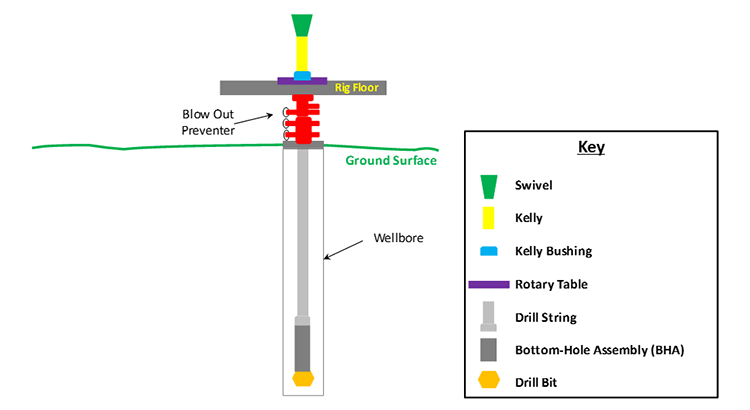
Kelly bushing is that elevated device positioned right on top of the rotary table and used to transmit torque from the rotary table to the kelly. The kelly bushing is designed to be the connection between the rotary table and the kelly. The kelly is a 4 or 6 sided steel pipe.
The purpose of the rotary table is to generate the rotary action (torque) and power necessary to rotate the drillstring and drill a well. The torque generated by the rotary table is useless if it is not transferred to the kelly (the drillstring is connected to the kelly).
Hence, through the kelly bushing the torque generated at the rotary table is transferred to the kelly. To achieve this connection, the inside profile of the kelly bushing matches the outer profile of the kelly so that the kelly fits or “sits” comfortably in the kelly bushing.
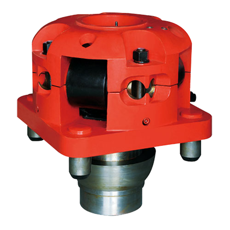
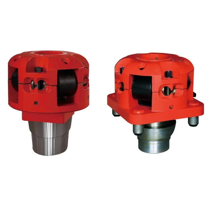
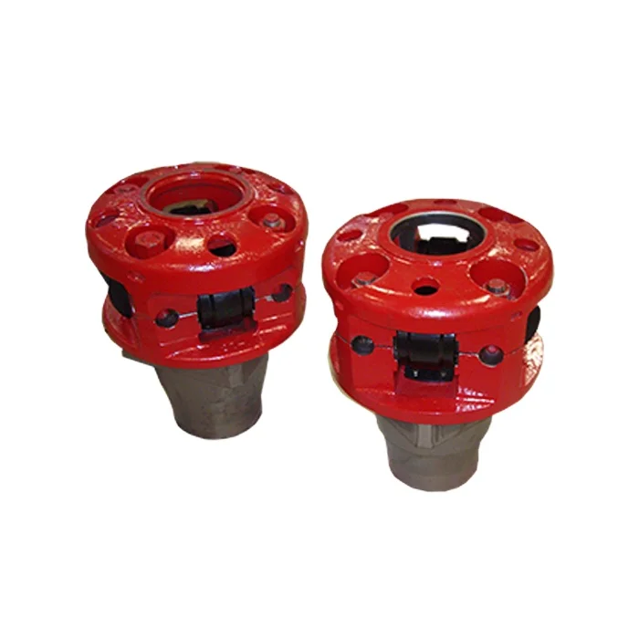
There are various designs for the kelly bushing including the split type, the pin-drive type and the square-drive type. Each of these designs has different ways in which they are connected and disconnected from the rotary table.
The internal diameter of the kelly bushing can be cut into the shape of a square (4-sided) or a hexagon (6-sided) depending on the outer shape of the kelly that will be used. The internals of a Kelly bushing is designed to resemble the outer shape of a Kelly just like the insides of a key lock is cut to exactly match the outer shape of the key.
The kelly bushing is not designed to hold tightly onto the Kelly; the kelly is still permitted to move up and down through the kelly bushing. This requirement is a must since drilling cannot progress if the kelly remains on a fixed spot. As the well is drilled deeper, the kelly also moves downward through the Kelly bushing.
The kelly bushing is sometimes used as a reference point from which depth measurements can be taken. All depths must be recorded with respect to a reference point; the kelly bushing (KB) is one of the depth references used in the oil and gas industry.
The top of the kelly bushing is normally used as the depth reference.For example, 7500ft KB means 7500ft below the kelly bushing or 7500ft measured from the top of the kelly bushing down to that point in the well.
In some other cases, depths could be recorded as 7500ft MDBKB meaning 7500ft measured depth below the kelly bushing. This is mostly used when the measured depth is different from the true vertical depth of the well, common with deviated and horizontal wells.

The square or hexagonal shaped steel pipe connecting the swivel to the drill string. The kelly moves through the rotary table and transmits torque to the drill string.
Square- or hexagonal-shaped steel pipe connecting the swivel to the drill pipe. NOTE The kelly moves through the rotary table and transmits torque to the drill stem.
The square, hexagonal or other shaped steel pipe connecting the swivel to the drill pipe. The kelly moves through the kelly bushings, rotary table and rotates the drill string.
The uppermost component of the drill string; the kelly is an extra-heavy joint of pipe with flat or fluted sides that is free to move vertically through a “kelly bushing” in the rotary table; the kelly bushing imparts torque to the kelly and thereby the drill string is rotated.
The uppermost component of the drill string; the kelly is an extra-heavy joint of pipe with flat or fluted sides that is free to move vertically through a “kelly bushing” in the rotary table; the kelly bushing imparts torque to the kelly and thereby the drill string is rotated.
“Kelly” means a 3 or more sided shaped steel pipe connecting the swivel to the drill pipe. The kelly moves through the kelly bushing and the rotary table and transmits torque to the drill string. [Mich. Admin. Code R 408 (2013)].
The square or other shaped steel pipe connecting the swivel to the drill pipe. The kelly moves through the rotary table and transmits torque to the drill string.

A kelly drive is a type of well drilling device on an oil or gas drilling rig that employs a section of pipe with a polygonal (three-, four-, six-, or eight-sided) or splined outer surface, which passes through the matching polygonal or splined kelly (mating) bushing and rotary table. This bushing is rotated via the rotary table and thus the pipe and the attached drill string turn while the polygonal pipe is free to slide vertically in the bushing as the bit digs the well deeper. When drilling, the drill bit is attached at the end of the drill string and thus the kelly drive provides the means to turn the bit (assuming that a downhole motor is not being used).
The kelly is the polygonal tubing and the kelly bushing is the mechanical device that turns the kelly when rotated by the rotary table. Together they are referred to as a kelly drive. The upper end of the kelly is screwed into the swivel, using a left-hand thread to preclude loosening from the right-hand torque applied below. The kelly typically is about 10 ft (3 m) longer than the drill pipe segments, thus leaving a portion of newly drilled hole open below the bit after a new length of pipe has been added ("making a connection") and the drill string has been lowered until the kelly bushing engages again in the rotary table.
The kelly hose is the flexible, high-pressure hose connected from the standpipe to a gooseneck pipe on a swivel above the kelly and allows the free vertical movement of the kelly while facilitating the flow of the drilling fluid down the drill string. It generally is of steel-reinforced rubber construction but also assemblies of Chiksan steel pipe and swivels are used.
The kelly is below the swivel. It is a pipe with either four or six flat sides. A rotary bushing fits around the flat sides to provide the torque needed to turn the kelly and the drill string. Rollers in the bushing permit the kelly free movement vertically while rotating. Since kelly threads would be difficult to replace, normally the lower end of the kelly has saver sub — or a short piece of pipe — that can be refurbished more cheaply than the kelly. Usually, a ball valve, called the lower kelly cock, is positioned between the kelly and the kelly saver sub. This valve is used for well control if the surface pressure becomes too high for the rotary hose or surface conditions.
According to the ″Dictionary of Petroleum Exploration, Drilling and Production″, ″[The] kelly was named after Michael J. (King) Kelly, a Chicago baseball player (1880-1887) who was known for his base running and long slides.″

In the oil and gas industry, depth in a well is the measurement, for any point in that well, of the distance between a reference point or elevation, and that point. It is the most common method of reference for locations in the well, and therefore, in oil industry speech, "depth" also refers to the location itself.
By extension, depth can refer to locations below, or distances from, a reference point or elevation, even when there is no well. In that sense, depth is a concept related to elevation, albeit in the opposite direction. Depth in a well is not necessarily measured vertically or along a straight line.
Because wells are not always drilled vertically, there may be two "depths" for every given point in a wellbore: the borehole, and the datum and the point in the wellbore. In perfectly vertical wells, the TVD equals the MD; otherwise, the TVD is less than the MD measured from the same datum. Common datums used are ground level (GL), drilling rig floor (DF), Rotary table (RT), kelly bushing (KB or RKB) and mean sea level (MSL).
Although it is an intuitive concept, depth in a well is the source of much confusion because it is frequently not specified correctly. Absolute depth should always be specified with three components:
Well depth values taken during the drilling operation are referred to as "driller"s depth". The "total depth" for the well, core depths and all analysis of core / mud and other materials from the drilling hole are measured in "drillers depth".
The differences between loggers and drillers depths are due to different stretch in the drilling string when drilling, and the wire line entered into the bore hole during wireline logging operations. This difference is estimated and referred to as "core shift". A core from a certain drillers depth is lined up with a wireline log (loggers depth) and structures in the core are compared with the log and matched.
Sign Convention - Depth increases positive in the downward direction. This may seem intuitive but confusion can arise when using certain references while integrating data from different sources. Workers mapping surfaces typically use elevation which, by convention, increases positive in the upward direction. Be mindful when integrating depth and elevation. For example, shallow wells drilled onshore often encounter reservoir at negative depths when referenced to sea level, mappers would define these same reservoirs at positive elevations when referenced to sea level.
The term "subsea" (SS) by itself should not be used, as it is ambiguous. It could mean: below sea floor or bottom, below mean sea level (MSL), below lowest astronomical tide (LAT), etc.
The acronym TVDSS is commonly used in the oil industry to represent TVD minus the elevation above mean sea level of the depth reference point of the well. The depth reference point is the kelly bushing in the United States and a few other nations, but is the drill floor in most places.
Differential (or relative) depths or thicknesses should generally be specified with at least two components: a unit and a path, plus any eventual specifiers to remove any possible ambiguity. No specifier should ever be left "implicit" or "understood". There are cases where a path is not needed and in fact should not be specified, because it is defined by the specifier, e.g. isochore (true stratigraphic thickness, independent of well path or inclination).
The distinction between "loggers" depth" and "drillers" depth" is becoming blurred due to the increasing use of logs acquired while drilling (LWD). At the time of writing, the common practice remains that the petrophysicists or geologists define the "official depths" in a well, and these depths are frequently different from the "drillers" depth", after various corrections, tie-ins, etc., have been applied.
Petrophysicists and drilling operations tend to express depths with reference to the rotary table or the original drill floor; geologists tend to use a common datum such as the mean sea level; geophysicists use the mean sea level. This can introduce much confusion when a unit is not specified with all 3 components: unit, path, and reference.
Path: common expressions of path are measured depth (MD) – elsewhere often known as along hole depth (AHD) – and true vertical depth (TVD). Note that using TV for true vertical depth is not consistent with the use of MD for measured depth, hence the recommended TVD.
the legal datum offshore Australia is Lowest Astronomical Tide (LAT) – (Ref. 1 & 2). Note that this requirement in itself can cause difficulties as it is difficult to measure offshore and can vary greatly between locations and even with time. There is, however, an advantage to this convention: tidal corrections should always be of the same sign (negative depth), i.e. the sea level is always higher than or equal to LAT.
Common references used in operations include: Rotary Table (RT), Drill Floor (DF), Kelly Bushing (KB), Sea Bottom (SB), Ground Level (GL), Casing Bowl Flange (CBF).
Specification of a differential depth or a thickness: in Figure 2 above, the thickness of the reservoir penetrated by the well might be 57 mMD or 42 mTVD, even though the reservoir true stratigraphic thickness in that area (or isopach) might be only 10 m, and its true vertical thickness (isochore), 14 m.
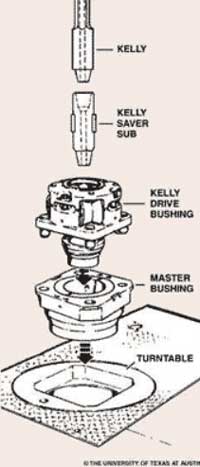
An adapter that serves to connect the rotary table to the kelly. The kelly bushing has an inside diameter profile that matches that of the kelly, usually square or hexagonal. It is connected to the rotary table by four large steel pins that fit into mating holes in the rotary table. The rotary motion from the rotary table is transmitted to the bushing through the pins, and then to the kelly itself through the square or hexagonal flat surfaces between the kelly and the kelly bushing. The kelly then turns the entire drillstring because it is screwed into the top of the drillstring itself. Depth measurements are commonly referenced to the KB, such as 8327 ft KB, meaning 8327 feet below the kelly bushing.
A large valve, usually installed above the ram preventers, that forms a seal in the annular space between the pipe and well bore. If no pipe is present, it forms a seal on the well bore itself. See blowout preventer.†
A blowout preventer that uses rams to seal off pressure on a hole that is with or without pipe. It is also called a ram preventer. Ram-type preventers have interchangeable ram blocks to accommodate different O.D. drill pipe, casing, or tubing.†
A pit in the ground to provide additional height between the rig floor and the well head to accommodate the installation of blowout preventers, ratholes, mouseholes, and so forth. It also collects drainage water and other fluids for disposal.†
The arrangement of piping and special valves, called chokes, through which drilling mud is circulated when the blowout preventers are closed to control the pressures encountered during a kick.†
A centrifugal device for removing sand from drilling fluid to prevent abrasion of the pumps. It may be operated mechanically or by a fast-moving stream of fluid inside a special cone-shaped vessel, in which case it is sometimes called a hydrocyclone.†
A centrifugal device, similar to a desander, used to remove very fine particles, or silt, from drilling fluid. This keeps the amount of solids in the fluid to the lowest possible level.†
The hoisting mechanism on a drilling rig. It is essentially a large winch that spools off or takes in the drilling line and thus raises or lowers the drill stem and bit.†
The cutting or boring element used in drilling oil and gas wells. Most bits used in rotary drilling are roller-cone bits. The bit consists of the cutting elements and the circulating element. The circulating element permits the passage of drilling fluid and uses the hydraulic force of the fluid stream to improve drilling rates.†
A heavy, thick-walled tube, usually steel, used between the drill pipe and the bit in the drill stem. It is used to put weight on the bit so that the bit can drill.†
A wire rope hoisting line, reeved on sheaves of the crown block and traveling block (in effect a block and tackle). Its primary purpose is to hoist or lower drill pipe or casing from or into a well. Also, a wire rope used to support the drilling tools.†
On diesel electric rigs, powerful diesel engines drive large electric generators. The generators produce electricity that flows through cables to electric switches and control equipment enclosed in a control cabinet or panel. Electricity is fed to electric motors via the panel.†
A large, hook-shaped device from which the elevator bails or the swivel is suspended. It is designed to carry maximum loads ranging from 100 to 650 tons and turns on bearings in its supporting housing.†
The heavy square or hexagonal steel member suspended from the swivel through the rotary table. It is connected to the topmost joint of drill pipe to turn the drill stem as the rotary table turns.†
A device fitted to the rotary table through which the kelly passes. It is the means by which the torque of the rotary table is transmitted to the kelly and to the drill stem. Also called the drive bushing.†
A portable derrick capable of being erected as a unit, as distinguished from a standard derrick, which cannot be raised to a working position as a unit.†
A series of open tanks, usually made of steel plates, through which the drilling mud is cycled to allow sand and sediments to settle out. Additives are mixed with the mud in the pit, and the fluid is temporarily stored there before being pumped back into the well. Mud pit compartments are also called shaker pits, settling pits, and suction pits, depending on their main purpose.†
A diesel, Liquefied Petroleum Gas (LPG), natural gas, or gasoline engine, along with a mechanical transmission and generator for producing power for the drilling rig. Newer rigs use electric generators to power electric motors on the other parts of the rig.†
A hole in the rig floor 30 to 35 feet deep, lined with casing that projects above the floor. The kelly is placed in the rathole when hoisting operations are in progress.†
The hose on a rotary drilling rig that conducts the drilling fluid from the mud pump and standpipe to the swivel and kelly; also called the mud hose or the kelly hose.†
The principal component of a rotary, or rotary machine, used to turn the drill stem and support the drilling assembly. It has a beveled gear arrangement to create the rotational motion and an opening into which bushings are fitted to drive and support the drilling assembly.
A series of trays with sieves or screens that vibrate to remove cuttings from circulating fluid in rotary drilling operations. The size of the openings in the sieve is selected to match the size of the solids in the drilling fluid and the anticipated size of cuttings. Also called a shaker.†
Wedge-shaped pieces of metal with teeth or other gripping elements that are used to prevent pipe from slipping down into the hole or to hold pipe in place. Rotary slips fit around the drill pipe and wedge against the master bushing to support the pipe. Power slips are pneumatically or hydraulically actuated devices that allow the crew to dispense with the manual handling of slips when making a connection. Packers and other down hole equipment are secured in position by slips that engage the pipe by action directed at the surface.†
A relatively short length of chain attached to the tong pull chain on the manual tongs used to make up drill pipe. The spinning chain is attached to the pull chain so that a crew member can wrap the spinning chain several times around the tool joint box of a joint of drill pipe suspended in the rotary table. After crew members stab the pin of another tool joint into the box end, one of them then grasps the end of the spinning chain and with a rapid upward motion of the wrist "throws the spinning chain"-that is, causes it to unwrap from the box and coil upward onto the body of the joint stabbed into the box. The driller then actuates the makeup cathead to pull the chain off of the pipe body, which causes the pipe to spin and thus the pin threads to spin into the box.†
A vertical pipe rising along the side of the derrick or mast. It joins the discharge line leading from the mud pump to the rotary hose and through which mud is pumped going into the hole.†
A rotary tool that is hung from the rotary hook and traveling block to suspend and permit free rotation of the drill stem. It also provides a connection for the rotary hose and a passageway for the flow of drilling fluid into the drill stem.†
The top drive rotates the drill string end bit without the use of a kelly and rotary table. The top drive is operated from a control console on the rig floor.†

The kelly is a primary link between the drilling rig’s surface equipment and the bit, and is therefore a critical component of the rotary system. Although top drive systems have replaced kelly/rotary table combinations on many rigs, some knowledge of their manufacture and operation is useful.
Their angled surfaces, or drive flats, are designed to fit into a drive roller assembly on the kelly bushing, so that as the rotary table turns to the right, the kelly turns with it. To allow for normal right-hand rotation of the drill string, kellys have right-hand threads on their bottom connections and left-hand threads on their top connections.
The American Petroleum Institute has established manufacturing and design standards for kellys, and has included them in the follwoing publications:API RP 7G, Recommended Practice for Drill Stem Design and Operating Limits.
For a kelly to be efficient in turning the drill string, the clearance between its drive flat surfaces and the rollers in the kelly bushing must be kept to a minimum. Kellys most often wear out due to a rounding-off of the drive corners, as shown in Figure 1 (new kelly with new drive assembly) and Figure 2 (worn kelly with worn drive assembly).
For minimal rounding, there must be a close fit between the kelly and the roller assembly, with the rollers fitting the largest spot on the kelly flats. Manufacturing techniques and rig operating practices play important roles in determining this fit.
Both square and hexagonal kellys are manufactured either from bars with an “as-forged” drive section, or from bars with fully-machined drive sections. Forged kellys are cheaper to manufacture. But machined kellys tend to last longer because:Unlike forged kellys, machined kellys are not subject to the metallurgical process of decarburization, which leaves a relatively soft layer of material on the drive surface that can accelerate the rounding process and increase the potential for fatigue cracks;
To minimize rounding, rig personnel should follow these guidelines (Brinegar, 1977):Always use new drive-bushing roller assemblies to break in a new kelly.
Frequently inspect and periodically replace drive assemblies to ensure that clearance and contact angle between the kelly and the rollers is held to a minimum;
Fatigue failures are seldom a problem with kellys because of the high-quality steels used in their manufacture. Nevertheless, kellys should be regularly inspected for cracks and other signs of wear, particularly within the threaded connections, in the areas where the flats join the upper and lower upsets and in the center of the drive section.
In general, the stress level for a given tensile load is less in the drive section of a hexagonal kelly than in the drive section of a square kelly of comparable size. Hexagonal kellys are thus likely to last longer than square kellys before failing under a given bending load.
Kellys can become crooked or bent due to improper handling. Examples of mishandling include dropping the kelly, misaligning it in the rathole and thereby exerting a side pull, using poor tie-down practices during rig moves, not using the kelly scabbard and improper loading or unloading techniques. Depending on where a bend is located, it may cause fatigue damage not only to the kelly but to the rest of the drill string, and can also result in uneven wear on the kelly bushing.
Unusual side motions or swaying of the swivel are good indicators of a crooked kelly. A good field service shop has equipment for straightening bent kellys, making this an easily-corrected problem.
A kelly saver subshould always be run between the kelly and the top joint of drill pipe. This protects the kelly’s lower connection threads from wear, as joints of drill pipe are continually made up and broken out. A saver sub is much less expensive and much easier to replace than the kelly itself, and it can also be equipped with a rubber protector to help keep the kelly centralized and to protect the top joint of casing against wear.
A kelly cock is a valve installed above or below the kelly, which prevents fluid from escaping through the drill string if the well should begin to flow or “kick.” As an extra well control precaution, an upper kelly cock (having left-hand threads) should be installed directly above the kelly, while a lower kelly cock (having right-hand threads) should be installed below the kelly. Installing two kelly cocks ensures that at least one of them is always accessible, regardless of the kelly’s position.
Automatic check valves, designed to close when the mud pumps are shut off, are also available, and can be installed below the kelly to prevent mud from spilling onto the rig floor during connections.

This invention pertains to kelly drives used in the rotary method of drilling. More particularly the invention pertains to roller kelly drive bushings adapted to fit in the master bushing of a rotary table such as used in drilling for oil by the rotary method.
Briefly the invention includes a body having a circular base beneath which extends a square pin adapted to be received in the square socket of a rotary table master bushing and above which extend four pairs of posts providing four sets of shaft support holes. The posts of each pair are asymmetrically placed relative to the base diameters. Between each pair of posts is pivotally mounted an H shaped cage with a shaft extending through the cross bar of the H shaped cage into the pair of support holes provided by the posts, the cage cross bar having a bushing where it pivots about the shaft. Each cage carries a pair of rollers rotatably mounted on shafts carried by the opposite ends of the cage, the rollers being provided with bushings to rotate on the shafts. Releasable means is provided to fix each cage and roller shaft against rotation and prevent axial motion thereof. Each cage and roller shaft has an axial grease passage therethrough joining radial passages communicating with the exterior of the shaft within the corresponding bushing. Each bushing is recessed adjacent the ends of the radial passages in the shaft to communicate the grease with the whole periphery of the shaft. Spring pressed ball check valves in the ends of the axial passages through the shafts provide means for introducing grease. Different sizes and shapes of rollers can be used. A lower cylindrical housing is secured to the body on top of the base; an upper housing is releasably connected to the tops of the posts. Ports in the housings permit access to the grease valves for lubricating the shafts and bushings.
Advantages of the construction include the direct lubrication of each roller as well as each cage, with provision for the escape of used grease between rollers and cage, whereby used grease can be completely flushed out and replaced and the grease escaping between rollers and cage provides seals against entrance of dirt and other foreign matter into the bearing area.
The centrally pivoted cage mounted rollers cause the kelly to be driven smoothly without wobbling, whip, vibration, or binding during axial feed, despite misalignment of the rotary table and crown block and despite crookedness of the kelly, while assuring positive drive and adequate dispersal of driving pressure on the kelly. This arises by virtue of the kinematic geometry of the pivot cage mounted rollers whereby the normal tolerances needed to fit any bushing around a kelly allow the caged rollers to align themselves with the kelly despite such misalignment and crookedness. The resulting absence of bending moments in the kelly reduces wear and vibration and prevents binding. The kinematics of the caged rollers makes it impossible for but one of the rollers of each cage to take all of the driving torque, thereby insuring adequate dispersal of driving pressure and avoiding Brinnelling of the kelly.
The ready removal and replacement of the roller cage shafts makes it a simple matter to remove two adjacent cages so that the apparatus can be threaded over the enlarged end of a kelly and the cages replaced prior to use.
T he construction is strong and rugged and able to withstand the customary oil field abuse as well as last a long time under intended conditions of use.
The adaptability of the apparatus to use with standard A.P.I. master bushings and the easy removal and replacement of the roller shafts whereby change of rollers to fit difierent sizes and shapes of kellys is facilitated makes the apparatus of wide applicability.
FIGURE 1 is a front elevation of a kelly bushing embodying the invention having rollers therein adapted to engage a square kelly of medium size, the housings being cut away in vertical section to show the interior of the apparatus, and portions of the front cage and lower roller being sectioned to show the lubrication systems therefor;
FIGURE 2 is a plan View of the FIGURE 1 apparatus with both of the housings broken away and one cage broken away partially to show the lower roller, different rollers having been substituted suitable for use with a large size hexagonal kelly;
FIGURE 3 is a perspective of the apparatus of FIG- URE 2 showing the exterior thereof, the apparatus being shown disposed in a rotary table and around a hexagonal kelly, and illustrating the manner of servicing the bearings.
Referring now to FIGURES l and 2, the twoapparatuses being identical except for the rollers, there is shown a body 10 having a circular base portion 11. Beneath the base extends a square pin 12 adapted to fit in the master bushing of a conventional rotary table. The upper portion 13 of the base 11 is of reduced diameter providing a shoulder 14 on which rests a cylindrical lower husing :15. The lower housing is welded to the base at 16.
There is a circular cross section passage 20 through the body adapted to receive a kelly such as hexagonal kelly 21, shown only in FIGURE 2 (and FIGURE 3). There is a counterbore 22 in the lower end of pin 12 adapted to rest on the pin of a support in the rat hole (not shown) when the kelly and kelly bushing are not in use: Preferably passage 20 is slightly flaring downwardly, as shown in FIGURE 1, to facilitate placement thereof over the upper end of a kelly.
The body it further includes four pairs of posts 30- 31, 32-493,. 34-35, 3637. For added strength each post is joined at its inner edge to the adjacent post of the adjacent pair as shown at 33 forming an angle. On top of the angles are arcuate plates 39, 49, 41, 42. Preferably, the body including pin, base, posts and plates is an integral steel casting.
Each plate is provided with a hole 50 beneath which is disposed a threaded nut 51 welded to the plate concentrio with the hole. The peripheries of plates 39-42 are of less radial extent than the outer edges of the posts leaving shoulders such as 56., 57 to facilitate placement of an per housing 58. Housing 58 is dome shaped and has an opening 59 through the top thereof through which a kelly may pass. There are four indented portions such as 60, 61 around the upper housing, the lower portions of which are fiat and adapted to rest on top of the plates. There is a hole through each indented portion of the upper housing adapted to receive a screw such as 62, 63 which engages the nuts beneath the plates to hold the housing in position.
Each pair of posts such as 30, 31, provides a pair of aligned support holes such as 70, 71 adapted to receive a shaft such as 72. Each shaft 72 is slightly bevelled at its ends as shown at 73 to facilitate placement in the support holes. An arcuate recess 74 is formed on each end of the shafts 72 to receive the overlapping edge of a retaining washer 76 which holds the shaft against both axial and rotary motion relative to the post. Washer 76 is held in place by socket headed screw 77". To facilitate placement of shaft 72 in support holes 70, 71 and alignment of arcuate recess 74 with washer 76, the ends of the shaft are slotted as shown at 78.
Each shaft 72 has a cage 80 pivotally mounted thereon. Each cage is of H shape with a hole 81 through the cross bar receiving the corresponding shaft 72. The holes 81 are provided with bronze bushing sleeves 82. Within each sleeve 82 is an annular grease reservoir groove 83. Communicating with groove 83 are radial passages 84, 85 in the shaft 72 which connect to axial passage 86 extending from one end of shaft 72 to the other. The ends of passage 86 are counterbored and threaded as shown at 87, 88 to receive check valve fittings 89 adapted to be connected to a conventional grease gun. Referring momentarily to FIGURE 3, four openings 90 spaced around the lower housing 15 provide access to the grease check valve fittings without the necessity of removing the housings.
Returning to FIGURES 1 and 2, when grease is pumped through a check valve 89 it goes through an axial passage 86 and out through radial passages 84, 85 into annular reservoir 83 and thence out between the bushing sleeve 82 and shaft 72, flushing out the old grease ahead of it. The grease escaping at the ends of shaft "72 goes into the space between bosses 90, 91 on the cage and bosses 92, 93 on the posts forming a seal against entrance of dirt, water and other foreign matter to the bearing area between sleeve82 and shaft 72.
Between the pairs of legs 101-102, 101"-102 at the"upper and lower ends of each H-shaped cage 80 are rotatably mounted rollers such as rollers 103, 104, 105", 106" shown in FIGURE 1. The rollers are mounted on shafts such as 107 on which rollers 104 is mounted. Each roller has a bushing sleeve such as 108 in roller 104. Shaft 107 is prevented from turning and moving axially by washers such as 109, 110, similar to the mounting of shaft 72. Shafts 107 and bushing sleeves 108 are provided with axial, radial, and annular grease passages 111, 112, 113 similar to those of shaft 72 and sleeve 82, to which grease is pumped through check valves 114, 115, screwed into counterbores 116, 117 in the ends of the shaft 107. When it is desired to lubricate the rollers, a conventional grease gun is used the same as for the cage.
One of each pair of posts is provided with a port such as 120, 121 and the adjacent post of the adjacent pair is provided with a channel such as 122, 123 whereby a grease gun can be connected to one of the grease check valve fittings of each lower roller while it is mounted in its cage and the cage is mounted between its support posts. The upper rollers are on shafts above the level of the tops of the posts and plates so they can be lubricated from both ends. As shown in FIGURE 3, four sets of upper ports 130 and four sets of lower ports 131 make it possible to lubricate the rollers without removing the housings. Lower ports 131 are aligned with channels 122, 123 and the holes 120, 121 in the posts.
When the grease in the roller lubrication passages is flushed out, the excess grease exuding between the ends of bushing sleeves 108 and shafts 107 escapes into the space between bosses 140, 141 on the inside of the cage and the adjacent sides of the rollers to form seals against dirt, water and other foreign matter.
Referring particularly to FIGURE 2, there are shown the rollers used to drive a hexagonal kelly. In the cages 80, on the front and back sides of the apparatus there are cylindrical rollers such as 151, 152 in the tops of the cages and like rollers in the bottoms of the cages. In the cages 153, 154 at the sides of the apparatus are disposed pairs of rollers such as upper roller 155 and lower roller 156. Top roller 155 in cage 153 is conical and adapted to engage a side of the kelly adjacent the side engaged by roller 151. The roller in the bottom of cage 153 is similar to roller 156 and is adapted to engage the side of the kelly adjacent to the side engaged by roller 152. Similarly the upper and lower rollers of cage 154 are adapted to engage different sides of the kelly.
It will be noted that the pairs of posts supporting each roller are asymmetrically located with respect to the diameters through the center of the kelly perpendicular to the roller axes, being displaced clockwise, so that when larger diameter rollers are used to drive smaller size kellys, the rollers do not interfere, while at the same time each roller bears at or near the leading corner of the adjacent side of the kelly where it has the maximum torque radius. The posts provide means holding each cage against all rotation about a vertical axis relative to the body 10.
It is because of the asymmetric positioning of the pairs of posts that the two rollers for the side cages are of different shape to engage the two different sides of the kelly. The roller 156, engaging the side of the kelly, has its largest cone diameter at the end of the roller nearest the perpendicular diameter (the diameter through the kelly center and perpendicular to the roller axis). Therefore the largest cone diameter of roller 156 is smaller than that of roller 155 whose largest cone diameter is at the end of the roller farthest from the perpendicular diameter. Because the largest diameter of roller 156 is smaller, it is necessary to discontinue the cone taper after it leaves the kelly and finish off with a cylindrical portion 181. The juncture between the conical and cylindrical portions is provided with a stress relief groove 182.
The reason roller 155 of larger cone diameter is preferably placed at the top of the side cages is because there"is more room at the top under the upper housing than there is at the bottom above the base.
When larger diameter rollers are substituted to engage a smaller kelly, the cylindrical rollers are bevelled on their ends that are farthest from the perpendicular diameter. This is shown at 191, 192, 193 in FIGURE 1. This provides additional clearance without reducing the area of contact with the kelly which in such case has smaller sides available for contact by the rollers.
In operation of the kelly bushing above described, it is to be noted that if a cage tilts so that one of its rollers is out of contact with the kelly or has less contact pressure than the other, there is created a torque automatically turning the cage about its axis to equalize the pressures of the upper and lower rollers. The same torque also automatically places each cage parallel to the kelly axis instead of placing a bending moment on the kelly to align it with the cage. These are marked advantages over roller kelly bushings having the rollers mounted on fixed axes.
In connection with the alignment of the cages with the kelly, it is to be noted that when the cages turn out of their vertical positions in order to follow a crooked or non-vertical kelly, the distance between the cages is reduced slightly. However with the usual tolerances required to manufacture and assemble the apparatus and to place it over a kelly, the distance between the cages and their rollers is not reduced to a point sufficient to bind on the kelly until the cage has moved far more than the maximum amount needed to accommodate any deviation of the kelly from vertical that is to be expected in practice. The elasticity of the materials increases the amount of angular displacement of the cages possible without binding on the kelly.
The housings around the cages and rollers permit them to operate while the apparatus is rotating with a rotary table without danger to personnel adjacent thereto. The bearings of the cage and rollers are easily serviced Without removing the protecting housings, thereby reducing the likelihood of the housings being left olf or the servicing being omitted.
While a preferred embodiment of the invention has been shown and described many modifications thereof can be made by one skilled in the art without departing from the spirit of the invention and it is desired to protect by Letters Patent all forms of the invention falling within the scope of the following claims.
1. A roller kelly bushing comprising a body having a vertical hole therethrough to receive a kelly, a plurality of pairs of cages, the cages of each pair being disposed on diametrically opposite sides of said hole, means independently pivotally mounting each cage directly on the body for rotation about a horizontal axis perpendicular to a radius from said hole extending through the cage and simultaneously holding the cage against all rotation about a vertical axis relative to said body, each cage having a roller rotatably mounted thereon above the cage pivot axis and another roller rotatably mounted thereon below the cage pivot axis, the position of each of said pairs of cages being unaffected by the rotation of the other of said pairs of cages.
2. The combination of claim 1 in which each cage is of H shape with the bar of the H forming the pivot axis of the cage and the rollers are pivotally mounted between the ends of the upper and the lower pairs of legs of the cage.
3. A roller kelly bushing comprising a body including a base having a vertical hole therethrough to receive a kelly and four pairs of vertical posts on the upper side of of the base, four shafts disposed with one between each pair of posts with its axis horizontal, said pairs of posts being placed so as to locate said four shafts with the axis of each lying along a different one of the four sides of a rectangle extending around said hole, fou-r cages each independently pivotally mounted on one of said shafts for rotation about the axis thereof, the location of said shafts disposing said cages in two pairs with the cages in each pair on opposite sides of said hole, each cage having a roller rotatably mounted thereon above the cage pivot axis and another roller rotatably mounted thereon below the cage pivot axis, the rollers of one cage of one pair of cages being adapted to engage one side of a kelly and the rollers of the other cage of said one pair being adapted to engage the opposite side of the kelly and said cages of said one pair rotating equal amounts about their shafts in case of misalignment of the kelly, the position of the other of said pairs of cages being unaffected by the rotation about its shafts of said one of said pairs of cages, said posts holding said cages against all rotation about a vertical axis relative to said body and against all rotation about a horizontal axis other than the axis of said shaft.
4. A roller kelly bushing comprising a body including a base having a vertical hole therethrough to receive a kelly and a plurality of pairs of vertical posts on the upper side of the base, a shaft disposed between each pair of posts with its axis horizontal and perpendicular to a radius from the hole, a plurality of cages each pivotally mounted on one of said shafts for rotation about the axis thereof, each cage being of H shape with the bar of the H forming the pivot axis of the cage, eagh cage having a roller rotatably mounted thereon between the upper legs of the H and another roller rotatably mounted thereon between the lower legs of the H.
5. A roller kelly bushing comprising a base having a hole vertically therethrough to receive a kelly and a plurality of cages each pivotally mounted thereon for rotation about a horizontal axis, each cage having a roller rotatably mounted thereon above the cage pivot axis and another roller rotatably mounted thereon below the cage pivot axis, characterized by the fact that there are four pairs of posts, four cages, one cage being mounted between each of the four pairs of posts, the pairs of posts are equally spaced around the top of the base, the rollers on two opposite cages all have cylindrical portions for contacting a kelly, and the other two cages have conical rollers for contacting a kelly, the upper and lower conical rollers in each of the last two said cages tapering in opposite directions.
References Cited in the file of this patent UNITED STATES PATENTS 1,020,210 Lobnitz Mar. 12, 1912 1,656,456 Trout Jan. 17, 1928 2,169,264 Long Aug. 15, 1939 2,202,446 Esseling May 28, 1940 2,312,323 Derrick Mar. 2, 1943 FOREIGN PATENTS 620,446 Germany Oct. 21, 1935 661,080 France Feb. 26, 1929 957,424 Germany Jan. 31, 1957

This website is using a security service to protect itself from online attacks. The action you just performed triggered the security solution. There are several actions that could trigger this block including submitting a certain word or phrase, a SQL command or malformed data.
This website is using a security service to protect itself from online attacks. The action you just performed triggered the security solution. There are several actions that could trigger this block including submitting a certain word or phrase, a SQL command or malformed data.
The global kelly drive market was valued at $1.6 billion in 2021, and is projected to reach $2.3 billion by 2031, growing at a CAGR of 3.7% from 2022 to 2031.
Report Key HighlightersThe kelly drive market is consolidated in nature with few players such as NOV Inc., SANY Group, BAUER Maschinen GmbH (Subsidiary of BAUER Group), Jereh Global Development LLC (As a Subsidiary of Jareh Group) and Liebherr-International Deutschland GmbH. that hold significant share of the market.
The study covers in-depth analysis of 16 countries from different regions including North America, Europe, Asia-Pacific, and LAMEA. In addition, country-wise data of every country has been provided for better understanding of kelly drive market dynamics in every country.
A kelly drive is a particular kind of well drilling tool which uses a section of pipe with a polygonal or splined outer surface and feeds it through a rotary table and matching kelly (mating) bushing which have the same shape or splines. The Kelly is a long, four- or six-sided steel bar having a hole bored through the center to allow drilling fluid to pass through. The kelly bushing allows the drill string to be lifted or lowered while it rotates by transferring rotating motion from the rotary table or kelly bushing to the drill string. Crewmembers make up several attachments to the kelly. The attachments include the upper kelly cock, the lower kelly cock (drill pipe safety valve), and the kelly saver sub.
Kelly drilling is one of the most used dry rotary drilling techniques. The kelly drive is used to create large-diameter bored piles (from a size of approx. 500 mm). With the increasing drilling activities is booting the kelly drive market share in coming year. The kelly drive works with almost any kind of rock and soil. According to kelly drive market forecast, the demand for short rotary drilling instruments, such as augers, core barrels, buckets, and specialized drilling tools which are used to move the dirt will be more in the market. The drill rod which is also known as a kelly bar, is a typical component of this drilling technique. The strong kelly bars enables deep drilling and help in boosting the kelly drive market trend in forecast period.
Globally, there has been a surge in oil exploration activity, which is driving the demand for kelly drive in rig and drilling industry. Apart from the pandemic time, a boom in exploration has tripled over the last five years. Kelly drive market analysis showcase the owing to a global boom in exploration of oil reserves, several oil companies are getting into the rig sector. With the ongoing expansion in petroleum products, large oil extraction companies are contracting with drilling equipment manufacturers for the rent and sale of drilling equipment. Oil exploration companies and equipment companies collaborate to provide offshore support services that can increase production. Factor such as oil exploration activities is likely to boost the market for kelly drive in near future.
Advances in technology and equipment have enabled more oil and natural gas to be recovered from the length of each well, improving production and reducing the environmental footprint of energy production. Kelly drive is cheaper however, technology is slow, inefficient, and unsafe as compared to the other technology which are present or coming in the market. These factors may restrain customers from using kelly drive; thus, hampering the market growth.
With combination of seismic surveys and drilling wells, companies are doing the search of oil reserve and deposits beneath the surface of the earth. Exploration projects can be expensive, time-consuming, and risky, drilling a well may cost tens of millions of dollars. Several factors are considered the number of wells to be drilled, recovery method, type of installation to be used, separation systems for the gas & fluids, and how the oil and gas will be transported to a processing facility. High demand for the petroleum products in the market resulting into several new excavations projects in different regions. This factor is anticipated to increase the sales of kelly drive; thus, creating lucrative kelly drive market opportunities.
The kelly drive market is segmented into product type, and region. On the basis of product type, the market is bifurcated into cleaners, braking oil, grease and lubes, degreaser, and others. Region-wise, the market is studied across North America, Europe, Asia-Pacific, and LAMEA.
In 2021, the square kelly segment was the largest revenue generator, and is anticipated to grow at a CAGR of 3.6% during the forecast period. With the increasing horizontal drilling operations result in increasing demand for square kelly in the market. To increase the output from a single well, drilling square kelly equipment are being used frequently in the market. Square Kelly is advantageous for end-users, however equipment can be used for both onshore and offshore drilling operations. Drilling activities are becoming more challenging which are demanding the high quality of kelly equipment. Several oil firms engage in new types of drilling on land, such as horizontal well drilling which covers a significantly larger area under the earth. With the increasing horizontal well drilling creates the opportunity for square kelly segment in global kelly drive market.
In 2021, the kelly bar segment was the largest revenue generator, and is anticipated to grow at a CAGR of 4.0% during the forecast period. With the increasing number of excavation projects and finding of deep oil reserves will increase the demand for kelly bars in the market. Companies are entering into the agreement for the drilling operations which is driving the kelly bars market. Today, reserves are found very deep under the land of sea which require the high strength bars for handling the pressure. Vertical and horizontal drilling activities are increasing which is increasing the demand for different shapes of kelly bars.
In 2021, the onshore segment was the largest revenue generator, and is anticipated to grow at a CAGR of 3.8% during the forecast period. The rise in production activities and decrease in non-productive time are anticipated to propel the market for the onshore segment during the coming years. The onshore oilfields in North America and LAMEA have witnessed a high market share, regions mainly focus on efficiency improvement, decline in non-productive drilling activity time, and enhancement in health, safety, and environment aspects while drilling.
The North America kelly drive market size is projected to grow at the highest CAGR during the forecast period. The region is experiencing more drilling activities of oil and gas extraction as the demand for oil-related goods rises worldwide. Kelly drive equipment is particularly helpful for drilling through hard rock and getting to the oil deposits. The Kelly Drive can be used to reduce operational expenses in drilling operations. For field operators and engineers, it ensures long-term project success and a high rate of return.
LAMEA was the second-largest contributor in terms of revenue in the global kelly drive market in 2021, and is anticipated to grow at a CAGR of 3.8% during the forecast period. Accelerated investment across the upstream sector along with crude oil price recovery will foster the drilling activities in the region. Robust growth in petrochemical products demand along with increase in industrial and commercial activities across the developing economies will boost the kelly drive market growth in LAMEA region.
For instance, The natural gas production in Saudi Arabia has been planned to increase by two-fold in the coming decade, which is expected to result in increased drilling activities related to gas production.
The leading players operating in the global kelly drive market include, NOV Inc., SANY Group, BAUER Maschinen GmbH (Subsidiary of BAUER Group), Jereh Global Development LLC (As a Subsidiary of Jareh Group) and Liebherr-International Deutschland GmbH, Bridges Equipment LTD, Lake Petro., TEXAS INTERNATIONAL OILFIELD TOOLS, LTD, Goldman, Tianhe Oil Group Co. Ltd., XI"AN KINGWELL OILFIELD MACHINERY CO.,LTD, El Didi Group.
Key benefits for stakeholdersPorter’s five forces analysis helps analyze the potential of buyers & suppliers and the competitive scenario of the industry for strategy building.
It outlines the current Kelly drive market trends and future estimations from 2021 to 2031 to understand the prevailing opportunities and potential investment pockets.
The invasion of Russia has further worsened an already precarious scenario for the energy and drilling markets, notably in Europe. To minimize the possibility of an interruption in Russian oil and gas supply, oil and gas corporations must collaborate with governments. In longer term, the sector needs to increase its adaptability and relevance in a rapidly evolving energy environment. The scenario brought about by the conflict between Russia and Ukraine influences the Kelly Drive market as well. Many projects that were previously underway in the nations are now on hold, and new projects are being delayed, which has slowed the market"s expansion in recent years.

This website is using a security service to protect itself from online attacks. The action you just performed triggered the security solution. There are several actions that could trigger this block including submitting a certain word or phrase, a SQL command or malformed data.

PROMT.One (Online-Translator.com) is a free online translator and dictionary in 20+ languages. Enjoy accurate, natural-sounding translations powered by PROMT Neural Machine Translation (NMT) technology, already used by many big companies and institutions companies and institutions worldwide.
Look up translations for words and idioms in the online dictionary, and listen to how words are being pronounced by native speakers. PROMT dictionaries for English, German, French, Russian, Spanish, Italian, and Portuguese contain millions of words and phrases as well as contemporary colloquial vocabulary, monitored and updated by our linguists.
UTM ZONE: Universal Transverse Mercator. The UTM system applies the Universal Transverse Mercator projection to mapping the world, using 60 pre-defined standard zones to supply parameters. UTM zones are six degrees wide. Each zone exists in a North and South variant.
EASTING: First measurement of a grid reference used to specify the location of a point on a rectangular coordinate system. The distance measured eastward from the origin of a rectangular coordinate system.
NORTHING: Second measurement of a grid reference used to specify the location of a point on a rectangular coordinate system. The distance measured northward from the origin of a rectangular coordinate system.
TW TIME: Two-way time in seconds for a seismic signal to travel from the source to the subsurface reflector and return to the detector, corrected to the reference datum.
C6_13C_VPDB(): Carbon isotope (13C/12C) ratio of hexane isomers in the gas relative to the Pee Dee Belemnite standard in per mil or parts per thousand.
C1_D_VSMOW(): Deuterium isotope (2H/1H) ratio of methane in the gas relative to the Vienna Standard Mean Ocean Water in per mil or parts per thousand.
C2_D_VSMOW(): Deuterium isotope (2H/1H) ratio of ethane in the gas relative to the Vienna Standard Mean Ocean Water in per mil or parts per thousand.
C3_D_VSMOW(): Deuterium isotope (2H/1H) ratio of propane in the gas relative to the Vienna Standard Mean Ocean Water in per mil or parts per thousand.
IC4_D_VSMOW(): Deuterium isotope (2H/1H) ratio of isobutane in the gas relative to the Vienna Standard Mean Ocean Water in per mil or parts per thousand.
NC4_D_VSMOW(): Deuterium isotope (2H/1H) ratio of butane in the gas relative to the Vienna Standard Mean Ocean Water in per mil or parts per thousand.
IC5_D_VSMOW(): Deuterium isotope (2H/1H) ratio of isopentane in the gas relative to the Vienna Standard Mean Ocean Water in per mil or parts per thousand.
NC5_D_VSMOW(): Deuterium isotope (2H/1H) ratio of pentane in the gas relative to the Vienna Standard Mean Ocean Water in per mil or parts per thousand.
C6_D_VSMOW(): Deuterium isotope (2H/1H) ratio of hexane isomers in the gas relative to the Vienna Standard Mean Ocean Water in per mil or parts per thousand.
API GRAVITY(deg): API gravity. American Petroleum Institute measure of density for petroleum that is measured at 15 �C. API gravity = (141.5 �/specific gravity at 16 �C) � 131.5 �.
SEQ_NO_FRACTION: Sequence number/repeat/duplicate run number assigned when the same fraction of an oil is separated into its components (saturated hydrocarbons, aromatic hydrocarbons and polars) by column chromatography.
C27T_C27: Ratio of C27 17α(H),18α(H)-25,28,30-trisnorhopane/ C27 18α(H)-22,29,30-trisnorneohopane + C27 17α(H)-22,29,30-trisnorhopane. [C27T/(TS+TM)].
PREFERRED/ALTERNATE: The codes �P" and �A" refer to the preferred and alternate depth for a datum respectively. This field is closely linked to the confidence rating and applies only to pick type Z. Often two depths are given for one of these datums. The one preferred by the palaeontologist is called the preferred depth. If, however, this pick carries a low confidence rating, then a second, alternate depth may also be provided.
CONFIDENCE CODE: Code indicating the sample type or nature of the event recognised and the confidence of the sample analysis (1 = excellent, 9 = bad), eg �Horizon 2" and �Ditch Cut 5".


 8613371530291