
derrick floor versus kelly bushing free sample
Because wells are not always drilled vertically, there may be two "depths" for every given point in a wellbore: the borehole, and the datum and the point in the wellbore. In perfectly vertical wells, the TVD equals the MD; otherwise, the TVD is less than the MD measured from the same datum. Common datums used are ground level (GL), drilling rig floor (DF), Rotary table (RT), kelly bushing (KB or RKB) and mean sea level (MSL).
The term "subsea" (SS) by itself should not be used, as it is ambiguous. It could mean: below sea floor or bottom, below mean sea level (MSL), below lowest astronomical tide (LAT), etc.
The acronym TVDSS is commonly used in the oil industry to represent TVD minus the elevation above mean sea level of the depth reference point of the well. The depth reference point is the kelly bushing in the United States and a few other nations, but is the drill floor in most places.
Petrophysicists and drilling operations tend to express depths with reference to the rotary table or the original drill floor; geologists tend to use a common datum such as the mean sea level; geophysicists use the mean sea level. This can introduce much confusion when a unit is not specified with all 3 components: unit, path, and reference.
Common references used in operations include: Rotary Table (RT), Drill Floor (DF), Kelly Bushing (KB), Sea Bottom (SB), Ground Level (GL), Casing Bowl Flange (CBF).

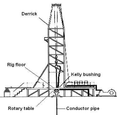
n: a large load-bearing structure, usually of bolted construction. In drilling, the standard derrick has four legs standing at the corners of the substructure and reaching to the crown block. The substructure is an assembly of heavy beams used to elevate the derrick and provide space to install blowout preventers, casingheads, and so forth.
n: all members in the assembly used for rotary drilling from the swivel to the bit, including the kelly, the drill pipe and tool joints, the drill collars, the stabilizers, and various specialty items. Compare drill string.
n: the column, or string, of drill pipe with attached tool joints that transmits fluid and rotational power from the kelly to the drill collars and the bit. Often, the term is loosely applied to include both drill pipe and drill collars.
A pit in the ground to provide additional height between the rig floor and the well head to accommodate the installation of blowout preventers, ratholes, mouseholes, and so forth. It also collects drainage water and other fluids for disposal.†
A small enclosure on the rig floor used as an office for the driller or as a storehouse for small objects. Also, any small building used as an office or for storage.†
A device fitted to the rotary table through which the kelly passes. It is the means by which the torque of the rotary table is transmitted to the kelly and to the drill stem. Also called the drive bushing.†
A portable derrick capable of being erected as a unit, as distinguished from a standard derrick, which cannot be raised to a working position as a unit.†
The derrickman"s working platform. Double board, tribble board, fourable board; a monkey board located at a height in the derrick or mast equal to two, three, or four lengths of pipe respectively.†
Shallow bores under the rig floor, usually lined with pipe, in which joints of drill pipe are temporarily suspended for later connection to the drill string.†
A hole in the rig floor 30 to 35 feet deep, lined with casing that projects above the floor. The kelly is placed in the rathole when hoisting operations are in progress.†
Shallow bores under the rig floor, usually lined with pipe, in which joints of drill pipe are temporarily suspended for later connection to the drill string.†
The hose on a rotary drilling rig that conducts the drilling fluid from the mud pump and standpipe to the swivel and kelly; also called the mud hose or the kelly hose.†
The principal component of a rotary, or rotary machine, used to turn the drill stem and support the drilling assembly. It has a beveled gear arrangement to create the rotational motion and an opening into which bushings are fitted to drive and support the drilling assembly.
Wedge-shaped pieces of metal with teeth or other gripping elements that are used to prevent pipe from slipping down into the hole or to hold pipe in place. Rotary slips fit around the drill pipe and wedge against the master bushing to support the pipe. Power slips are pneumatically or hydraulically actuated devices that allow the crew to dispense with the manual handling of slips when making a connection. Packers and other down hole equipment are secured in position by slips that engage the pipe by action directed at the surface.†
A vertical pipe rising along the side of the derrick or mast. It joins the discharge line leading from the mud pump to the rotary hose and through which mud is pumped going into the hole.†
The top drive rotates the drill string end bit without the use of a kelly and rotary table. The top drive is operated from a control console on the rig floor.†

Because wells are not always drilled vertically, there may be two “depths” for every given point in a wellbore: the measured depth (MD) measured along the path of the borehole, and the true vertical depth (TVD), the absolute vertical distance between the datum and the point in the wellbore. In perfectly vertical wells, the TVD equals the MD; otherwise, the TVD is less than the MD measured from the same datum. Common datums used are ground level (GL), drilling rig floor (DF), rotary table (RT), kelly bushing (KB) and mean sea level (MSL). [1]
Kelly Bushing Height (KB):The height of the drilling floor above the ground level. Many wellbore depth measurements are taken from the Kelly Bushing. The Kelly bushing elevation is calculated by adding the ground level to the Kelly bushing height.
Driller’s Depth below rotary table (DDbrt): The depth of a well or features within the wellbore as measured while drilling. The measured length of each joint of drillpipe or tubing is added to provide a total depth or measurement to the point of interest. Drillers depth is the first depth measurement of a wellbore and is taken from the rotary table level on the rig floor. In most cases, subsequent depth measurements, such as those made during the well completion phase, are corrected to the wellhead datum that is based on drillers depth (reference: Schlumberger Oilfield Glossary).

A 27-year-old gas drilling rig worker died on May 23, 2003 from blunt force trauma to the head, neck, and chest during a cleanout operation at the well. At the time of the incident, the victim was working within eight feet of the kelly on the drilling rig floor. Compressed air was used to blow out the conductor pipe, but due to a lack of communication, the compressor was turned on before the valves were prepared to control the flow of debris out of the hole. The excess pressure caused the kelly bushing, drillpipe slips, and debris to be blown out of the rotary table. The victim was struck by these objects and was pronounced dead on arrival to the hospital.
A 27-year-old gas drilling rig worker died on May 23, 2003 from blunt force trauma to the head, neck, and chest after he was struck by the kelly bushing and drillpipe slips. OKFACE investigators reviewed the death certificate, related local news articles, and reports from the sheriff’s office, Medical Examiner, Occupational Safety and Health Administration (OSHA),
At the time of the incident, the rig floor and working surfaces were level and dry; the weather was warm with light to no wind. The victim was working with four other crew members on a gas drilling rig, wearing the necessary personal protective equipment (e.g., steel toe boots, hard hat, eye protection). Prior to the incident, the decedent was assigned the task of driller and was asked to find the bottom of the conductor hole with the kelly (Figure 2). The kelly is used to transmit power (rotary motion) from the rotary table and kelly bushing to the drillstring (Table 1). After unlatching the brake handle, the driller allowed the kelly to free fall to the bottom. The uncontrolled fall caused the kelly to become jammed with debris, such as water, mud, and other material, that had collected in the conductor hole since the time it was originally drilled for the well. As a result, a cleanout operation became necessary. Cleanout procedures involving air or mud drilling fluid are acceptable norms in the oil and gas drilling industry; however, drilling fluid is more commonly used than compressed air.
a long square or hexagonal steel bar with a hole drilled through the middle for a fluid path; goes through the kelly bushing, which is driven by the rotary table
After the kelly became jammed, a senior driller was assigned to take over the brake handle and kelly; however, the decedent remained approximately eight feet away on the rig floor. A newly hired, yet experienced, derrickman had the job of running the air compressor. While the drillers were switching positions, the derrickman realized that he had not started that particular type of compressor in quite some time and left the rig floor to seek help from another driller onsite.
In normal cleanout operation procedures, certain valves are closed prior to turning on the compressed air, which allows control over the flow of debris out of the hole and into a catch pond. Once the valves are prepared, the driller indicates to the derrickman that the area is ready for the compressed air. At some point between the senior driller preparing for cleanout and the derrickman leaving the floor to turn on the air compressor, there was a lack of communication and the air compressor was activated without the senior driller’s knowledge, prior to the prescribed valves being shut. After starting the air compressor, the derrickman returned to the rig floor and, as he walked to his next assignment, the rotary table erupted. The pressure normally used to complete the cleanout work is a minimum of 20 pounds per square inch. Within minutes, the kelly had pressurized well beyond this point to 150 pounds per square inch. The victim, who was still on the rig floor in close proximity to the kelly, was also unaware that the air compressor had been turned on. The compressed air, at full pressure with no valves closed to control or direct the flow, blew the kelly bushing, drillpipe slips, and debris out of the rotary table; all of which struck and landed on the victim.

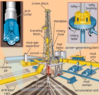
During the first phase of the development of the well, a rotary drilling rig is installed to bore a hole in the ground and reach the oil reservoir. The main rotary drilling rig components are derrick or mast, power and prime movers, hoisting equipment, rotating component, circulating system, tubular and tubular handling equipment and bit.
Derrick is mainly used offshore and is a large load-bearing vertical structure, usually of bolted construction and pyramidal in shape, for the equipment used to lower and raise the drill string into and out of the wellbore. The height of the derrick does not affect its load-bearing capacity, but it shows the maximum length of the drill pipe section. The standard derrick has square-shaped rig floor with four legs standing at the corners of the substructure. It provides work space for the necessary equipment on the rig floor.
Mast is mainly used with onshore rigs and is a portable derrick that can be raised as unit but for the transporting can be divided into two or more sections. It is usually rectangular or trapezoidal in shape.
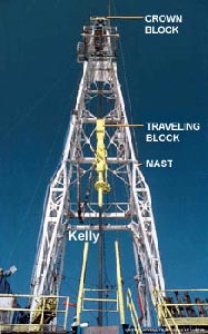
Crown block is fixed assembly of sheaves (single or double) with a wire rope drilling line running between it and is located at the top of the derrick or mast and over which the drilling line is threaded. It is used to change the direction of pull from the drawworks to the traveling block.
Traveling block and hook combination is used to safely and efficiently raise or lower tools and equipment in the well. It is the set of sheaves or pulleys through which the drill line (wire rope) is threaded or reeved, is opposite the crown block and enabling heavy loads to be lifted out of or lowered into the wellbore. Hook is located beneath the traveling block and is used to pick up and secure the swivel and Kelly.
Drill line is the wire rope used to support the drilling tools. It is threaded or reeved through the traveling block and crown block to facilitate the lowering and lifting of the drill string into and out of the borehole. Drill line then clamped to the rig floor by the deadline anchor.
Rotating component is the equipment responsible for rotating the drill string. It consists of the swivel, Kelly spinner, Kelly or top drive, Kelly bushing, master bushing and rotary table (Figure 5).Swivel is a mechanical device that is hung from the hook of the traveling block to support the weight of the drill string and allows it to rotate freely. It provides connection for the rotary hose as well as passageway for the flow of drilling fluid into the drill stem.
Kelly is the heavy steel square or hexagonal member that is suspended from the swivel through the rotary table and connected to the topmost joint of drill pipe to turn the drill stem as the rotary table turns. It has a hole drilled through the middle that permits fluid to be circulated into the drill stem and up the annulus or vice versa. The Kelly goes through the Kelly bushing, which is driven by the rotary table.
Top drive is a hydraulically powered device on the drilling rig and is located at the swivel place. It allows the drill stem to spin and facilitate the process of drilling a borehole. Top drive means a power swivel, which directly turns the drill string without need for a Kelly and rotary table.
Kelly bushing is a device that fits into a part of rotary table called master bushing, transmits torque to the Kelly and simultaneously permits vertical movement of the Kelly to make hole. The Kelly bushing as Kelly is square or hexagonal and has an inside profile matching the Kelly’s outside profile with slightly larger dimensions so that the Kelly can freely move up and down inside.
Master bushing is a tool that fits into the rotary table of a drilling rig to accommodate the slips and drive the Kelly bushing so that the rotating motion of the rotary table can be transmitted to the Kelly.
Rotary table is section of the drill floor used to turn the drill stem. It has a beveled gear arrangement to create the rotational motion and opening into which bushings are fitted to drive and support the drilling assembly.
Circulating component is the rig equipment responsible for the movement of drilling fluid within the well as well as solids removal incurred by the drilling fluid (Figure 6). Normally, the circulation would start from the mud pits or tanks that are located besides the rig. Powerful pumps force the drilling through the surface high-pressure connections to a set of valves called pump manifold, located at the derrick floor. Then, the fluid goes up the rig within a pipe called standpipe to approximately 1/3 of the height of the mast. From there, the drilling fluid flows through a flexible high-pressure rotary hose to the top of the drill string. The flexible hose allows the fluid to flow continuously as the drill string moves up and down during normal drilling operations. The fluid enters in the drill string through a special piece of equipment called swivel located at the top of the Kelly. The swivel permits rotating the drill string while the fluid is pumped through the drill string. In wellbore, the drilling fluid then floes down the rotating string and jets out through the nozzles in the drill bit at the bottom of the hole. Drilling fluid carrying the drilled cuttings and flows out the center of the drill bit and is forced back up the outside of the drill pipe between the drill string and walls of the well (annular) onto the surface of the ground where it is cleaned and circulated back to the well. The cleaning process starts from the shale shaker, which is basically a vibrating screen. This will remove the larger particles, while allowing the residue to pass into settling tanks. The finer material can be removed using other solids removal equipments such as desander and desilter. If the mud contains gas from the formation, it will be passed through a degasser that separates the gas from the liquid mud. Having passed through all the mud processing equipment, the mud is returned to the mud pits or tanks for recycling.
Iron roughneck is a pneumatically operated machine that replaces the functions performed by the Kelly spinner, drill pipe spinner and tongs and is used to connect and disconnect tubular.
At the present time, floating drilling vessels or barges are used to drill exploratory wells at oflshore locations. A typical floating drilling barge uses a rotary drilling rig, which employs a string of drill pipes and drill collars extending from the floating vessel down to the underwater formation. The drilling string is turned by a rotary table through which extends an elongated kelly joint of square cross section. The lower end of the kelly joint is connected to the upper end of the uppermost drill pipe, and the drilling string is lengthened or shortened by temporarily uncoupling the kelly joint and adding or removing a section of drill pipe. The drilling string is raised and lowered on a traveling block.
In conventional rotary drilling at onshore locations, rat and mouse holes are provided at the rig for the temporary storage of drill pipe or the kelly joint. A typical rat or mouse hole includes an upright scabbard closed at its bottom and set in a hole drilled at the well site. The scabbard is usually of sufficient length to accommodate one joint or section of drill pipe. Ordinarily, the term rat hole is used to designate the storage space for the kelly joint, and the term mouse hole is descriptive of the storage space for a section of drill pipe either just removed from the well or about to be placed into the Well.
In the preferred form, the invention contemplates apparatus for drilling a hole in a formation underlying a body of water which includes a floating vessel and means for anchoring the vessel over the formation. A rotary drilling rig is mounted on the vessel over the water, and a derrick floor is disposed over the water. A rotary table is mounted on the derrick floor and an outwardly extending track is mounted on the vessel with one end of the track nearer the rotary table than the other. A carriage is adapted to move on the track and an elongated and downwardly extending Scabbard is connected to the carriage. Means are provided for moving the carriage on the track to carry the Scabbard toward and away from the rotary table.
Referring to FIG. 1, a floating vessel 10, such as a barge or ship, is anchored by lines 11 in a body of water 1"2 over an underwater formation 23 in which a well 24 is being drilled. A draw works 25 and power unit 25, which may be of conventional type, are mounted on the deck of the vessel to operate a hoisting cable 27 carried over a crown block 28 at the upper end of a derrick 29. The traveling end of the hoisting cable carries a traveling block 30 and a hook 31 which supports a swivel joint 32 supplied with drilling fluid through a mud hose 32A connected to a pump (not shown). A kelly joint 33 extends downwardly from the swivel through a kelly bushing 34 in the center of a rotary table 36 mounted in a derrick floor 37, which extends across the base of the derrick. Preferably, the rotary table is mounted on gimbals in a manner such as that described in US. Reissue Patent No. 24,083. Power is supplied to the rotary table through a shaft 40 turned by a rotary table power unit 41. As can be seen most clearly from FIGS. 1 and 3, the rotary table is supported directly over a cellar 42 located in the center of the vessel. The cellar opens at its bottom into the water in which the vessel is floating.
A string of drill pipe 43 is connected to the lower end of the kelly and extends down through the cellar, the Water and into the well. A plurality of drill collars 46 are attached to the lower end of the drill pipe and a drill bit 47 is connected to the lower end of the drill collars.
Referring to FIG. 1, the derrick includes a pair of laterally spaced and vertical traveling block guides 59 which are attached to the derrick at their upper ends by horizontal sections "52. As shown most clearly in FIG. 2, each guide is an inwardly opening channel section adapted to receive a separate rotatable wheel 54 mounted on a respective shaft 56 between the outer ends of a guide bracket 58 connssted at its water to the traveling block. Thus, the traveling block is free to move vertically but is prevented from swinging laterally if the vessel should pitch or roll due to wave action.
A substantially upright scabbard 60 is disposed in the cellar 42. Preferably, the scabbard is a piece of pipe or casing open at both ends and connected near its upper end by a horizontal pivot 62 to a carriage 64 having a pair of inboard wheels 66 and a pair of outboard wheels 68 adapted to ride on an outwardly extending track 7t]! attached to the underside of the derrick floor with the inner end of the track adjacent the rotary table. The upper end of the scabbard is of increased diameter and projects up through a transverse scabbard-slot 72 in the derrick floor. The lower end of the Scabbard extends down below the bottom of the vessel through a loosely fitting loop 30 attached to the lower edge of the cellar. The inner end of a piston rodSZ is connected to the outboard end of the carriage and the outboardend of the piston rod is connected to a piston 84- disposed in a horizontal cylinder 86 secured by a brace "87 (FIG. to the track 70 and adapted to be supplied air at opposite ends by outboard and inboard airlines 83, 89 respectively, connected to a source of air pressure {not shown).
As shown most clearly in FIG. 4, the carriage includes a pair of laterally spaced and horizontal longitudinal beams 90 joined at their respective ends by cross beams 91. The track is made up of a pair of horizontal and laterally spaced I-beams or rails 92 having upper horizontal flanges 93 welded to the bottom of the derrick platform. Thus, the scabbard is adapted to pivot between the rails in a vertical plane perpendicular to the longitudinal axis of the vessel as the carriage is moved inwardly and outwardly with respect to the rotary table. As shown in FIG. 1, the carriage is in the outboard or retracted position so that the upper end of the scabbard is remote from the rotary table. A string of drill pipe is disposed in the scabbard and supported at its upper end by a supporting ring 94 having a downwardly extending and externally threaded boss 96 screwed into the upper end of the drill pipe as shown most clearly in FIG. 4. The supporting ring is of suflicient diameter to rest on the upper end of the scabbard and prevent the drill pipe, kelly joint, etc., from slipping down and out of the bottom of the scabbard.
Although for the sake of simplicity, only one scabbard and carriage arrangement is shown in FIG. 1, FIG. 3 shows how a plurality of scabbards can be mounted around the rotary table to slide in a direction transverse to the longitudinal axis of the floating vessel. This arrangement is preferred because it leaves a longitudinal space clear for the handling of casing 160 and drill pipe 102 longitudinally disposed on the deck of the vessel on either side of the derrick. If desired, the scabbard slots in the derrick floor for the various scabbards are covered with plates 104, when the scabbards are in their respective outboard positions, to provide a continuous working platform. When a scabbard is to be advanced toward the rotary table, its respective cover plate is first removed. As shown in FIG. 3, the center scabbard on the left hand side of the rotary table, which is the scabbard shown in FIGS. 1, 4 and 5, is in the inboard position i.e., moved in to be adjacent the rotary table.
The operation of the apparatus shown in the accompanying drawings is relatively simple. Whenever it is desired to store the kelly joint or other equipment such as the drill pipe or drill collars in the scabbard shown in FIGS. 1, 4 and 5, the drill string is secured in the rotary table by a set of slips (not shown). The cover plate (if used) for the scabbard slot is removed, the drill"string disconnected above the slips, and air is supplied through the outboard line 88 to drive the piston inwardly and carry the upper end of the scabbard closely adjacent the rotary table, the carriage rolling on the track 70. The lower end of the scabbard is held by the loop. 80-near the bottom edge -of the cellar-and is -fr"ee to slide up or down slightly as the scabbard moves inwardly or outwardly, the scabbard also being free to pivot in a vertical plane (as shown by the dotted line position of the scabbard in FIG. 5).
With the upper end of the scabbard adjacent the rotary table, as shown in FIG. 3, the lower end of the disconnected drill string above the rotary table, say the lower end of the kelly joint, is guided manually into the scabhard, and the draw works are actuated to lower the traveling block so that the kelly joint enters the scab hard. A pair of slips (not shown) are set to hold the kelly while it is disconnected from the swivel. The ring 94 is screwed into the upper end of the kelly, which is then lowered into the scabbard until the ring rests on the upper end of the scabbard as shown in FIGS. 1 and 4. Air pressure is then supplied to the cylinder 86 through inboard line 89 to drive the piston outwardiy and carry the upper end of the scabbard in an outboard direction until it comes to rest in a substantially vertical position along the adjacent wall of the cellar as shown in FIG. 1. The cover plate is then placed over the slot to provide a continuous floor area around the rotary table.
Thereafter, the swivel is replaced by elevators adapted to latch on to drill pipe, which may be withdrawn from the well and disconnected as described above, another scabbard being advanced to receive another section of the drill string. If the water is sufficiently deep, it is possible for all of the drill string to be stored in the various scabbards located around the rotary table. However, in usual practice the kelly joint isstored in one scabbard, the drill pipe removed and stacked on the deck of the drilling vessel, and then the drill collars are stored in the remaining scabbards. The drill pipe is of lighter construction than the drill collars, and therefore can be laid out on the deck in longer sections without danger of bending.
1. Apparatus for drilling a hole in a formation underlying a body of water comprising a floating vessel having a cellar opening at its bottom into the water, means for anchoring the vessel over the formation, a rotary drilling derrick mounted on the vessel over the cellar, a derrick floor disposed over the cellar, a rotary table mounted in the derrick floor, an outwardly extending track mounted on the vessel with one end nearer the rotary table than the other end, a carriage adapted to move on the track, an elongated and downwardly extending scabbard in the cellar, a pivot connecting the upper portion of the scabbard to the carriage, and means for moving the carriage to carry the scabbard toward and away from the rotary table.
4- Apparatus for-drilling a hole in a formation underlying a body of water comprising a floatingvessel having a cellar-opening at its bottom-into the water, means for anchoring the vessel over the formation, a rotary drilling derrick mounted on the vessel over the cellar, a derrick floor disposed over the cellar and having a slot, a rotary table mounted in the derrick floor, an outwardly extending track mounted on the vessel with one end nearer the rotary table than the other end, a carriage adapted to move on the track, an elongated and downwardly extending scabbard disposed in the cellar with its upper portion in the derrick floor slot, means connecting the scabbard to the carriage, and means for moving the carriage tobcarry the scabbard toward and away from the rotary ta le.
6. Apparatus for drilling a hole in a formation underlying a body of water comprising a floating vessel having a cellar opening at its bottom into the Water, means for anchoring the vessel over the formation, a rotary drilling derrick mounted on the vessel over the cellar, a derrick floor disposed over the cellar, a rotary table mounted in the derrick floor, a track extending transverse to the longitudinal axis of the vessel and mounted on the vessel with one end nearer the rotary table than the other end, a carriage adapted to move on the track, an elongated and downwardly extending scabbard in the cellar and connected to the carriage, and means for moving the carriage to carry the scabbard toward and away from the rotary table.
7. Apparatus for drilling a hole in a formation underlying a body of water comprising a floating vessel having a cellar opening at its bottom into the water, means for anchoring the vessel over the formation, a rotary drilling derrick mounted on the vessel over the cellar, a derrick floor disposed over the cellar, a rotary table mounted in the derrick floor, a pair of outwardly extending, horizontal and laterally spaced rails mounted on the vessel with one end nearer the rotary table than the other end, a carriage having wheels adapted to roll on the rails, an elongated and downwardly extending scabbard in the cellar and connected to the carriage, and means for mov ing the carriage along the rails to carry the scabbard toward and away from the rotary table.
8. Apparatus for drilling a hole in a formation underlying a body of water comprising a floating vessel, means for anchoring the vessel over the formation, a rotary drilling derrick mounted on the vessel over the water, a derrick floor disposed over the water, a rotary table mounted on the derrick floor, a traveling block mounted in the derrick, means for moving the traveling block substantially vertically above the rotary table, a substantially horizontal track mounted on the vessel with one portion nearer the rotary table than another portion, a carriage adapted to move on the track toward and away from the rotary table in a direction transverse to that in which the traveling block moves, an elongated and downwardly extending scabbard connected to the carriage, the scabbard having its upper end at a level in the vicinity of the rotary table and extending downwardly at least as far as about the bottom of the vessel and means for moving the carriage on the track to carry the scabbard toward and away from the rotary table.
10. Apparatus for drilling a hole in a formation underlying a body of water comprising a floating vessel having a cellar opening at its bottom into the water, means for anchoring the vessel over the formation, a rotary drilling derrick mounted on the vessel over the water, a derrick floor disposed over the cellar, a rotary table mounted on the derrick floor, a traveling block mounted in the derrick, means for moving the traveling block substantially vertically above the rotary table, a substantially horizontal track mounted on the vessel with one portion nearer the rotary table than another portion, a carriage adapted to move on the track toward and away from the rotary table in a direction transverse to that in which the traveling block moves, an elongated and downwardly extending scabbard connected to the carriage and disposed in the cellar, and means for moving the carriage on the track to carry the scabbard toward and :away from the rotary table.
12. Apparatus for drilling a hole in a formation underlying a body of water comprising a floating vessel, means for anchoring the vessel over the formation, a rotary drilling derrick mounted on the vessel over the water, a derrick floor disposed over the water, a rotary table mounted on the derrick floor, a traveling block mounted in the derrick, means for moving the traveling block substantially vertically above the rotary table, upright laterally rigid and elongated traveling block guide means disposed above the rotary table and adjacent the path traveled by the block to be immobile with respect to the derrick, and means engaging the guide means and block to permit the vertical movement of the traveling block and limit all of its lateral movement, a substantially horizontal track mounted on the vessel with one portion nearer the rotary table than another portion, a carriage adapted to move on the track toward and away from the rotary table in a direction transverse to that in which the traveling block moves, an elongated and downwardly extending scabbard connected to the carriage, and means for moving the carriage on the track to carry the scabbard toward and away from the rotary table.
13. Apparatus for drilling a hole in a formation unde lying a body of water comprising a floating vessel, means for anchoring the vessel over the formation, a rotary drilling derrick mounted on the vessel over the water, a derrick floor disposed over the water, a rotary table mounted on the derrick floor, a traveling block mounted in the derrick, means for moving the traveling block along a substantially vertical path above the rotary table, upright, laterally rigid and elongated traveling block guide means disposed adjacent the path traveled by the block to be immobile with respect to the derrick, and means engaging the guide means and block to be slidable along the guide and constrain all lateral movement of the traveling block as the vessel is pitched and rolled by wave action.


 8613371530291