
derrick floor versus kelly bushing brands
Fred Wilson Drilling Company appeals a final order of the Occupational Safety and Health Review Commission which sustained the administrative law judge"s ("ALJ") findings.1 The ALJ fined the drilling company $250 for violating standard 29 C.F.R. § 1910.36(b)(1) by failing to provide a "Geronimo" escape line for derrickmen working on the "monkey board" platform of its oil drilling rig number nine, and $100 for violating standard 29 C.F.R. § 1910.212(a)(1) by failing to guard the rig"s Kelly bushing and rotary table. We affirm the finding of liability for violation of the first standard; we vacate the second.
The monkey board is a horizontal platform on the derrick approximately ninety feet above the derrick floor and over 100 feet above ground. Employees work on this platform handling sections of drill pipe during drilling operations. Although there are a number of means of exit from this platform, the ALJ"s finding that no escape route accessible from the platform would allow descent other than straight down was uncontradicted. The Geronimo line, by providing a method of egress at an angle away from the derrick, provides a safe means of escape in the event of a fire or explosion resulting from drilling, and therefore satisfies 29 C.F.R. § 1910.36(b)(1). Because we find substantial evidence on the record as a whole to support the Commission"s factual determinations, 29 U.S.C. § 660(a), we affirm.
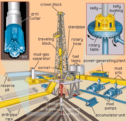
The drilling company was found in violation of the standard 29 C.F.R. § 1910.212(a)(1) for failure to guard the Kelly bushing and rotary table. The rotary table, flush with the derrick floor, is approximately three feet in diameter and is constantly rotating during the drilling process. The Kelly bushing rests upon the rotary table surrounding the Kelly, which is a heavy, vertical steel pipe. Power is transmitted from a bank of diesel engines, generators, or power units through a belt system to the rotary table/bushing unit. The rotary table turns the bushing, and together they transmit rotation power to the Kelly while simultaneously permitting vertical movement of the Kelly. The Kelly in turn transmits power to the drill string and cutting bit.
In finding Fred Wilson in violation of this standard, the ALJ acknowledged that use of a Kelly bushing guard would pose serious hazards, but concluded that an unguarded bushing, on balance, presented the more unsafe situation. Because Wilson appeared to have acted under a good faith belief that it might be more hazardous to use such a guard than not to use one, the ALJ reduced the penalty recommended by the Secretary from $250.00 to $100.00.
The ALJ based his finding on the testimony of an OSHA compliance officer whose familiarity with this particular aspect of the drilling industry appears to have been minimal. The inspector had never seen a Kelly bushing guard on any rigs he had inspected, had not visited a factory at which guards were manufactured and had never viewed a Kelly bushing guard other than in brochures published by their manufacturers. The officer admitted that he did not understand how a guard is placed on the rig and that he knew nothing of the maintenance of a Kelly bushing. Finally the officer conceded he did not know what effect a guard would have in the event a "blowout" occurred.
The ALJ also relied on the testimony of the president of the Kelly Bushing Guard Manufacturing Company, who is also the designer of the guard manufactured by his company. Although he had twenty-three years experience as a welder, he was not an engineer, had no formal education beyond the tenth grade, and had not had his guard independently tested. His company, which had been in business for less than a year at the time of the hearing, carried no products liability insurance and had sold only one guard.
Wilson, by contrast, presented the testimony of an oil well drilling expert who was familiar with a variety of Kelly bushing guards, and found that they created hazards by obstructing passageways on the limited space of the rig floor, by confining the drilling operator"s view of the Kelly, and by potentially acting as deflecting shields in the event of a blowout, thereby increasing the likelihood of a fire. Wilson"s Director of Safety and Personnel also testified and stated that the company had investigated the feasibility of using Kelly bushing guards, but had decided against their use because of the additional hazards created. He also testified that the company had no record of any accidents caused by a Kelly bushing in operation without a guard.
The administrative law judge in the case at bar did not, in his finding of fact, indicate that the bushing contained any j-bolts or other protuberances. In both Secretary of Labor v. Grey Wolf Drilling Co., OSHRC Docket No. 77-2328, 1978 (CCH) OSHD P 22,961 and Secretary of Labor v. Grey Wolf Drilling Co., OSHRC No. 77-3803, 1978 (CCH) OSHD P 23,183, the ALJ specifically found that an unguarded Kelly bushing which had no j-bolts or other protuberances constituted less of a hazard than one equipped with a guard. Although the ALJ in Secretary of Labor v. Signal Oilfield Service, Inc., OSHRC Docket No. 77-0226, 1978 (CCH) OSHD P 22,758 upheld the Secretary"s citation for failure to guard the Kelly, the ALJ specifically found that the Kelly bushing had at least four protrusions exposed around its outer perimeter. The court emphasized, however, that its holding did not apply to the new type Kelly bushing installed after the inspection which had a smooth exterior, a caveat noted and approved by the ALJ in the Grey Wolf decisions.
At oral argument in the case at bar, the assertion of Wilson"s counsel that its Kelly bushing was of the same nature and construction as that used in Grey Wolf was unrebutted. While noting that the OSHA compliance officer had testified that the Kelly bushing had protruding bolts, Wilson"s counsel explained that the officer, who, as noted, evinced no real knowledge of the drilling industry, must have been referring to the bevelled and rounded pins which fit into the rotary table. Complainant"s exhibit 10, a picture of the Kelly bushing, supports Wilson"s argument and reveals no j-bolts or other protrusions. Thus, every other administrative law judge that has considered this question has found that, given the present state of development, a Kelly bushing like Wilson"s constitutes more of a hazard guarded than unguarded. We believe the present record requires the same finding.
Oilfield workers have one of the most dangerous jobs in America. Over one hundred oil and gas extraction workers are killed on the job each year, not including the thousands who suffer career-ending injuries. The Occupational Safety and Health Administration (OSHA) closely regulates gas and oil extraction to minimize dangers on the rig floor. Some regulations mandate falling hazard protections, that is, hard hats, but workers in these designated hardhat areas face serious dangers beyond falling debris.
Roughnecks injured on the rig floor might have claims for damages in addition to compensation available through worker’s compensation. Connect with the experienced Texas oilfield injury attorneys at the Wyatt Law Firm for your free and confidential case review. We’ve recovered $3,900,000 for a client injured in an oilfield explosion and nearly $3,000,000 after a victim died due to industrial negligence. Let us see what we can do for you.
Welcome to the rig floor, where more oilfield accidents happen than any other location on the drilling rig. Roughnecks on the rig floor are some of the most prone to injury, positioned next to the moving drill string, using heavy tongs and fast-moving spinning chains, heaving the slips, and working around the rotary table.
Slipping and falling is probably the most common rig floor accident. Drilling mud and crude oil slicken the metal floors, even coating the rubber tread on work boots. Falling on the rig floor, however, also means possibly falling beneath or between heavy equipment. To prevent falls, staff must keep the rig floor tidy, and companies should take extra measures (adding non-slip mats, etc.).
Manning the tongs on the rig floor is a dangerous part of the job. Roughnecks use hydraulic or pneumatic metal tongs, which act like suspended pairs of giant pliers, to grab and wrench pipe sections while tripping in and out of the well. Roughnecks risk pinching and crushing injuries from tongs, especially on the fingers and hands. They can also be struck by swinging tongs or even falling tongs, which sometimes fail from lost bearings or pins, rusty chains, or corroded cables.
Some rigs still use spinning chains to screw pipe sections together faster, though many rigs phased them out due to high accident rates. The fast-moving chain can easily trap objects such as clothing and fingers as it’s strung around the pipe—causing injury and even amputation. Taut spinning chains can also unravel or break suddenly, whipping floorhands with enough force to break bones and lacerate skin.
The rotary table is a rotating section of the floor (on many rigs) that uses a kelly systemto spin the drill string through rock. It is most dangerous when people or other objects get caught in it. Getting caught between the kelly bushing and rotary mechanism can cause serious crushing injury, and the moving table itself poses a slipping hazard.
What goes up might come down. Roughnecks and floorhands work directly below anything that might fall from the derrick. Unfortunately, a lot of heavy things can fall from the derrick, including tools, pipes, the drill string, the top drive, the crown block, and other rig structuring during mechanical failure or rig collapse. Unpredictable accidents like these claim lives every year.
For example, spinal cord trauma costs injured workers between $1 million and $5 million in lifetime medical expenses, not including their lost wages, reduced earning capacity, and emotional suffering. Hold these negligent corporations fully accountable for your injuries with a dedicated rig floor accident lawyer.
Oil Rig Owners –Most employees on the rig floor do not work directly for the rig owner. Big oil companies and/or their subsidiaries generally own the rig, but contractors run day-to-day operations. The rig owner bears ultimate responsibility for keeping the worksite safe for contractors and employees. This includes clearing the rig floor of debris and slipping hazards, ensuring equipment functions safely, and putting safeguards in place for workers. While big oil companies contract these responsibilities out to others, it does not eliminate their legal obligations.
Drill Site Owners– Sometimes, the same companies own the rig and drill site, but in many cases, oil companies purchase the mineral (oil and gas) rights from property owners. Injured workers might also hold property owners liable for rig floor accidents under Texas premises liability law.
Drill Equipment Manufacturers – The dangers of the rig floor frequently stem from industrial drilling equipment. Manufacturers of these products may bear direct liability for injuries caused by defective, unsafe, or negligently designed products. This might include injuries caused when manufacturers do not provide proper warnings or instructions about certain hazards.
Injured roughnecks generally have multiple legal claims following rig floor accidents, but it’s essential to preserve evidence of transient conditions and defects. If possible, have co-workers take photographs of slipping hazards, broken/dangerous equipment, and safety violations. Claimants should also immediately report accidents, even seemingly minor falls, to safety supervisors. Many back and head injuries worsen in the hours and days following the initial injury. Contacting an oil and gas accident lawyer might also help claimants obtain essential witness testimony and video evidence before big oil companies interfere with the evidence.
Despite claims to the contrary, oil companies and drill site owners generally carry massive personal injury insurance policies. Claiming this coverage, however, requires legal assistance. Most third parties defer claims to workers’ compensation or deny primary liability. Many roughnecks do not pursue these claims after receiving the initial denial. Experienced catastrophic drill site accident lawyers know how to demand insurance settlements after rig floor accidents.
It costs a lot to follow OSHA safety standards on active drill sites. As such, it’s not uncommon for oil companies and contractors to cut corners. Some rig floor accidents occur after catastrophic safety failures that employees previously complained about. These cases—along with major safety failures – may trigger investigations into regulatory violations.
Roughnecks suffering from devastating and often disabling injuries seldom have the income necessary to pay high hourly legal rates. Most families are emotionally and financially struggling to get by following devastating rig floor accidents. As such, compassionate personal injury attorneys accept viable oil and gas cases on a contingency fee basis. This allows claimants to retain dedicated legal counsel with experience fighting big oil without any upfront fees or costs.
An adapter that serves to connect the rotary table to the kelly. The kelly bushing has an inside diameter profile that matches that of the kelly, usually square or hexagonal. It is connected to the rotary table by four large steel pins that fit into mating holes in the rotary table. The rotary motion from the rotary table is transmitted to the bushing through the pins, and then to the kelly itself through the square or hexagonal flat surfaces between the kelly and the kelly bushing. The kelly then turns the entire drillstring because it is screwed into the top of the drillstring itself. Depth measurements are commonly referenced to the KB, such as 8327 ft KB, meaning 8327 feet below the kelly bushing.
It is the drill collars, screwed onto the bottom of the drill pipe assembly just above the bit, that provide the necessary weight. Drill collars, along with drill pipe and bit all make up the drill string, which is rotated by the rotary table and the kelly. The drill string component parts are hollow down the middle so that the drilling fluid can be circulated down to the bit. A fluid-tight rotary joint, the swivel, is located at the top of the kelly and provides a connection between the mud pump discharge line and the inside of the drill string. A hoisting systemic required supporting the weight of the drill string, lowering it into the hole and pulling it out. This is the function of the derrick, the hook and the draw works.
Though drilling is the basic operation, it is the one that requires the fewest number of people. The driller operates the draw works alone. The rotary table rotates and drives the drilling bit by means of the drill string and the kelly. The main control device is the brake lever. The driller controls and regulates the downward movement of the hook by putting on the brake. According to the principle of rotary drilling, bits are used at constant weight. The weight of everything that is suspended from the hook is constant and the driller knows this information by reading the weight on the hook when the bit is off bottom (Fig. 1.4).
This is the difference that the driller reads on the weight indicator (commonly called Martin Decker). He must keep it constant by lowering the kelly at the same speed as the rate of penetration of the bit.
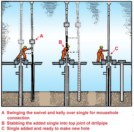
When the bit has drilled the equivalent of a length of pipe (30 ft), the drill string must be lengthened by screwing a new joint of drill pipe onto the bottom of the kelly. The sequence is illustrated in Figs. 1.5a, 1.5b, 1.5c and 1.5d:During drilling, the crew places a joint of pipe in a sheath, called the mousehole, located near the rotary table.
The driller engages the draw works to hoist the drill string to the first length of drillpipe under the kelly. The crew puts the slips in place and the kelly can be unscrewed since the drill string is supported by the rotary table. Mud circulation has of course been stopped. In Fig. 1.5b, the crew screws the kelly to the box end of the length of drillpipe in the mousehole. Pipe is screwed and made up in the mousehole.
The driller hoists the kelly and drillpipe with the drawworks (Fig. 1.5c). Once the new joint of pipe has been screwed and made up on the drill string, the driller resumes drilling fluid circulation.
The first step is to disconnect the swivel from the hook and place the kelly and the swivel – which is still connected to the mud pumps by the hose – in a sheath called the rathole (Fig. 1.6a).
The fourth length of pipe is clamped in the rotary table by the slips and the connection is unscrewed with the tongs (Fig. 1.6b). A stand of three lengths of pipe is then hanging from the elevator. The crew pushes the lower end of the stand so that is rests on the setback. Then the derrickman, who stands on the monkey board, unlatches the elevator, holds the stand and places the upper end of the stand in the pipe rack (Figs. 1.6c and 1.7).
The stand length depends on how high the derrick is. The largest rigs handle stands in threes, lightweight rigs in twos and the smallest ones can manage only singles. The running in or tripping in, operation is carried out in the same way.
During a round trip both rotation and circulation are at a standstill. If either is needed, the kelly is taken out of the rathole and screwed back onto the drill string.
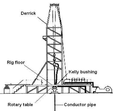
This type is the oldest and derives directly from the tower that used to be built of wood. It is in the shape of a sharply pointed pyramid with one „foot“ in each corner resting on the angles of a square. The square is the rig floor (Fig. 2.2).
An upper platform, the water table, is what holds the drilling line sheaves, or crown block. Another platform between the two (about 85 ft high) is where the derrickman stands to rack up the lengths of drillpipe or drill collars.
The metal structure of the derrick can be welded or bolted together. There are practically no more derricks for onshore drilling because dismantling and reassembling operations are long, dangerous and therefore no longer economically viable at all.
A distinctions is made between dynamic dericks and standard ones. The dynamic type is installed on floating supports such as ships and semisubmersibles. These derricks are subjected to extra dynamic stresses due to rolling, pitching and heaving of the support and to winds. The space available between the rig floor and the crown block must be higher to handle the wave-induced vertical movements of the floating support.
The mast is a structure shaped like a very pointed A. It has the particular feature of being rotary jointed at the base so that it can be assembled or dismantled horizontally and then pulled to an upright position using the draw works and a special hoisting cable. This type of drilling tower is well suited to onshore drilling rigs requiring good deal of mobility. The racking board is in a cantilever position and lengths of pipe are racked on a floor, called the setback that is separate from the mast structure.
These structures serve to raise the rig floor to leave room for wellhead assemblies and BOP stacks. They can be separate from the hoisting mast. Here they consist of box-like structures piled up on either side of the wellhead. The rig floor is assembled on top of the boxes and the hoisting mast sits directly on the box substructure. Most intermediate-capacity masts are an integral part of a hoisting assembly with an elevating substructure where the draw works and racking floors are folded at ground level by girders articulated in the shape of a parallelogram. Once the mast has been erected by the draw works, the floor is pulled into an unfolded position using the drilling line (Fig. 2.5).
The crown block is the set of pulleys that the drilling line passes through. It is supported by the top platform of the drilling mast or derrick. The load on the crown block, and in turn on the mast or derrick, is greater than the load on the hook. The reeving system is such that there are two more lines on the crown block, the deadline and the fastline which is connected to the draw works drum. If the reeving system has ten lines and the load on the hook is 150 t for example, the line is under 15 t of tension in static conditions. But the hook is 150 t for example; the line is under 15 t of tension in static conditions. But the crown block supports 150 t + 2 x 15 t, i.e. 180 t.
To hang the drill string on the rotary table, slips are placed in the master bushing (Fig. 2.10). For safer handling of slick drill collars, i.e. drill collars without any recess, a clamp is used on top of the slips. To make the crew´s work easier on the rig floor, some pipe slips are pneumatically powered and can be operated directly by the driller (Fig. 2.11).
This mechanical apparatus is very simple and requires only little maintenance, and this is what makes it so attractive for the working conditions on a rig. The main bearing supports the maximum load in static conditions or at slow rotation speed. During drilling (above 50 rpm) in fact, the weight of the drill string is hanging from the hook. Rotary table maintenance consists in checking the level and quality of the oil in the lubrication system. The nominal size is characterized by the through diameter where the master bushing is installed. The master bushing serves to hold the drill string by means of the slips and to drive the kelly drive bushing during drilling. Nominal sizes in inches may be as follows: 17½, 20½, 27½, 37½ and 49½.
The kelly can have a square, hexagonal or triangular cross-section. It is rotated by the table and by means of the kelly drive bushing that it fits into. The kelly bushing is equipped with four horizontal axis rollers so designed as to transmit torque to the kelly and in turn to the drill string screwed onto the lower kelly coupling. The whole assembly can slide freely up and down along the kelly´s stroke length. With a total length of 40 ft or 54 ft, the kelly has a useful stroke length of 37 ft or 51 ft respectively.
To control any incipient blowouts that might occur through the inside of the drill string, safety valves are mounted on each end of the kelly (lower kelly valve and upper kelly cock). The two valves are operated by rotating ninety degrees with a wrench that is kept on the rig floor. The lower valve must have a small enough diameter so that it can be run into the borehole that is being drilled.2.3.2.2 The kelly saver sub
Each time a length of drillpipe is added, i.e. after the useful length of the kelly has been drilled, the kelly must be unscrewed from the drill string, then screwed back onto it. Since this is done often, the drill string is screwed and unscrewed from a low-cost coupling rather than from the threads on the bottom of the kelly itself. Because the sub rotates inside the BOPs, a rubber protector is placed on the outside sub diameter to protect them from wear.2.3.2.3 The swivel
It should be noted that all connections above the useful section of the kelly have a left-handed thread so that they are not broken out by the rotary table turning to the right.
Though the advantages of the power swivel as described later on are very attractive, installing one entails a number of constraints:a dolly, or trolley beam guide system, must be installed in the derrick to absorb reactive torque,
The hydraulic fluid discharged by the pumps to the accumulators compresses a bladder filled with a compressible gas such as nitrogen. There is pressure equilibrium between gas and the fluid in the accumulator. The gas acts as a spring that expels the oil when the circuit is opened by means of one of the four-way valves that selects the functions. The valves can be operated directly or remote-controlled from the rig floor.
The hydraulic pumps (pneumatic or electric) start and stop automatically according to the accumulator pressure. The main circuit is regulated at 1500 psi, but there is a specialized circuit for the annular BOP where a regulator can adjust the pressure depending on requirements (stripping in particular). The driller can also control this circuit from the rig floor.

Drill floor (#21) is the area on the rig where the tools are located to make the connections of the drill pipe, bottom hole assembly, tools and bit. It is considered the main area where work is performed.
Drill pipe (#16) is a joint of hollow tubing used to connect the surface equipment to the bottom hole assembly (BHA) and acts as a conduit for the drilling fluid. In the diagram, these are stood in the derrick vertically, usually to save time while tripping pipe.
Goose-neck (#10) is a thick metal elbow connected to the swivel and standpipe that supports the weight of and provides a downward angle for the kelly hose to hang from.
Kelly drive (#19) is a square, hexagonal or octagonal shaped tubing that is inserted through and is an integral part of the rotary table that moves freely vertically while the rotary table turns it.
Kelly hose (#9) is a flexible, high pressure hose that connects the standpipe to the kelly (or more specifically to the gooseneck on the swivel above the kelly) and allows free vertical movement of the kelly, while facilitating the flow of the drilling fluid through the system and down the drill string.
Pipe rack (#17) is a part of the drill floor (#21) where the stands of drill pipe are stood upright. It is typically made of a metal frame structure with large wooden beams situated within it. The wood helps to protect the end of the drill pipe.
Stand (#16) is a section of 2 or 3 joints of drill pipe connected together and stood upright in the derrick. When they are pulled out of the hole, instead of laying down each joint of drill pipe, 2 or 3 joints are left connected together and stood in the derrick to save time.
Standpipe (#8) is a thick metal tubing, situated vertically along the derrick, that facilitates the flow of drilling fluid and has attached to it and supports one end of the kelly hose.
Vibrating hose (#6) is a flexible, high pressure hose (similar to the kelly hose) that connects the mud pump to the stand pipe. It is called the vibrating hose because it tends to vibrate and shake (sometimes violently) due to its close proximity to the mud pumps.ca:Torre de perforació

Because wells are not always drilled vertically, there may be two “depths” for every given point in a wellbore: the measured depth (MD) measured along the path of the borehole, and the true vertical depth (TVD), the absolute vertical distance between the datum and the point in the wellbore. In perfectly vertical wells, the TVD equals the MD; otherwise, the TVD is less than the MD measured from the same datum. Common datums used are ground level (GL), drilling rig floor (DF), rotary table (RT), kelly bushing (KB) and mean sea level (MSL). [1]
Kelly Bushing Height (KB):The height of the drilling floor above the ground level. Many wellbore depth measurements are taken from the Kelly Bushing. The Kelly bushing elevation is calculated by adding the ground level to the Kelly bushing height.
Driller’s Depth below rotary table (DDbrt): The depth of a well or features within the wellbore as measured while drilling. The measured length of each joint of drillpipe or tubing is added to provide a total depth or measurement to the point of interest. Drillers depth is the first depth measurement of a wellbore and is taken from the rotary table level on the rig floor. In most cases, subsequent depth measurements, such as those made during the well completion phase, are corrected to the wellhead datum that is based on drillers depth (reference: Schlumberger Oilfield Glossary).


 8613371530291