
kelly bushing diagram factory

This invention pertains to kelly drives used in the rotary method of drilling. More particularly the invention pertains to roller kelly drive bushings adapted to fit in the master bushing of a rotary table such as used in drilling for oil by the rotary method.
Briefly the invention includes a body having a circular base beneath which extends a square pin adapted to be received in the square socket of a rotary table master bushing and above which extend four pairs of posts providing four sets of shaft support holes. The posts of each pair are asymmetrically placed relative to the base diameters. Between each pair of posts is pivotally mounted an H shaped cage with a shaft extending through the cross bar of the H shaped cage into the pair of support holes provided by the posts, the cage cross bar having a bushing where it pivots about the shaft. Each cage carries a pair of rollers rotatably mounted on shafts carried by the opposite ends of the cage, the rollers being provided with bushings to rotate on the shafts. Releasable means is provided to fix each cage and roller shaft against rotation and prevent axial motion thereof. Each cage and roller shaft has an axial grease passage therethrough joining radial passages communicating with the exterior of the shaft within the corresponding bushing. Each bushing is recessed adjacent the ends of the radial passages in the shaft to communicate the grease with the whole periphery of the shaft. Spring pressed ball check valves in the ends of the axial passages through the shafts provide means for introducing grease. Different sizes and shapes of rollers can be used. A lower cylindrical housing is secured to the body on top of the base; an upper housing is releasably connected to the tops of the posts. Ports in the housings permit access to the grease valves for lubricating the shafts and bushings.
The centrally pivoted cage mounted rollers cause the kelly to be driven smoothly without wobbling, whip, vibration, or binding during axial feed, despite misalignment of the rotary table and crown block and despite crookedness of the kelly, while assuring positive drive and adequate dispersal of driving pressure on the kelly. This arises by virtue of the kinematic geometry of the pivot cage mounted rollers whereby the normal tolerances needed to fit any bushing around a kelly allow the caged rollers to align themselves with the kelly despite such misalignment and crookedness. The resulting absence of bending moments in the kelly reduces wear and vibration and prevents binding. The kinematics of the caged rollers makes it impossible for but one of the rollers of each cage to take all of the driving torque, thereby insuring adequate dispersal of driving pressure and avoiding Brinnelling of the kelly.
The ready removal and replacement of the roller cage shafts makes it a simple matter to remove two adjacent cages so that the apparatus can be threaded over the enlarged end of a kelly and the cages replaced prior to use.
The adaptability of the apparatus to use with standard A.P.I. master bushings and the easy removal and replacement of the roller shafts whereby change of rollers to fit difierent sizes and shapes of kellys is facilitated makes the apparatus of wide applicability.
FIGURE 1 is a front elevation of a kelly bushing embodying the invention having rollers therein adapted to engage a square kelly of medium size, the housings being cut away in vertical section to show the interior of the apparatus, and portions of the front cage and lower roller being sectioned to show the lubrication systems therefor;
FIGURE 2 is a plan View of the FIGURE 1 apparatus with both of the housings broken away and one cage broken away partially to show the lower roller, different rollers having been substituted suitable for use with a large size hexagonal kelly;
FIGURE 3 is a perspective of the apparatus of FIG- URE 2 showing the exterior thereof, the apparatus being shown disposed in a rotary table and around a hexagonal kelly, and illustrating the manner of servicing the bearings.
Referring now to FIGURES l and 2, the twoapparatuses being identical except for the rollers, there is shown a body 10 having a circular base portion 11. Beneath the base extends a square pin 12 adapted to fit in the master bushing of a conventional rotary table. The upper portion 13 of the base 11 is of reduced diameter providing a shoulder 14 on which rests a cylindrical lower husing :15. The lower housing is welded to the base at 16.
There is a circular cross section passage 20 through the body adapted to receive a kelly such as hexagonal kelly 21, shown only in FIGURE 2 (and FIGURE 3). There is a counterbore 22 in the lower end of pin 12 adapted to rest on the pin of a support in the rat hole (not shown) when the kelly and kelly bushing are not in use: Preferably passage 20 is slightly flaring downwardly, as shown in FIGURE 1, to facilitate placement thereof over the upper end of a kelly.
Each plate is provided with a hole 50 beneath which is disposed a threaded nut 51 welded to the plate concentrio with the hole. The peripheries of plates 39-42 are of less radial extent than the outer edges of the posts leaving shoulders such as 56., 57 to facilitate placement of an per housing 58. Housing 58 is dome shaped and has an opening 59 through the top thereof through which a kelly may pass. There are four indented portions such as 60, 61 around the upper housing, the lower portions of which are fiat and adapted to rest on top of the plates. There is a hole through each indented portion of the upper housing adapted to receive a screw such as 62, 63 which engages the nuts beneath the plates to hold the housing in position.
Each shaft 72 has a cage 80 pivotally mounted thereon. Each cage is of H shape with a hole 81 through the cross bar receiving the corresponding shaft 72. The holes 81 are provided with bronze bushing sleeves 82. Within each sleeve 82 is an annular grease reservoir groove 83. Communicating with groove 83 are radial passages 84, 85 in the shaft 72 which connect to axial passage 86 extending from one end of shaft 72 to the other. The ends of passage 86 are counterbored and threaded as shown at 87, 88 to receive check valve fittings 89 adapted to be connected to a conventional grease gun. Referring momentarily to FIGURE 3, four openings 90 spaced around the lower housing 15 provide access to the grease check valve fittings without the necessity of removing the housings.
Returning to FIGURES 1 and 2, when grease is pumped through a check valve 89 it goes through an axial passage 86 and out through radial passages 84, 85 into annular reservoir 83 and thence out between the bushing sleeve 82 and shaft 72, flushing out the old grease ahead of it. The grease escaping at the ends of shaft "72 goes into the space between bosses 90, 91 on the cage and bosses 92, 93 on the posts forming a seal against entrance of dirt, water and other foreign matter to the bearing area between sleeve82 and shaft 72.
Between the pairs of legs 101-102, 101"-102 at the"upper and lower ends of each H-shaped cage 80 are rotatably mounted rollers such as rollers 103, 104, 105", 106" shown in FIGURE 1. The rollers are mounted on shafts such as 107 on which rollers 104 is mounted. Each roller has a bushing sleeve such as 108 in roller 104. Shaft 107 is prevented from turning and moving axially by washers such as 109, 110, similar to the mounting of shaft 72. Shafts 107 and bushing sleeves 108 are provided with axial, radial, and annular grease passages 111, 112, 113 similar to those of shaft 72 and sleeve 82, to which grease is pumped through check valves 114, 115, screwed into counterbores 116, 117 in the ends of the shaft 107. When it is desired to lubricate the rollers, a conventional grease gun is used the same as for the cage.
When the grease in the roller lubrication passages is flushed out, the excess grease exuding between the ends of bushing sleeves 108 and shafts 107 escapes into the space between bosses 140, 141 on the inside of the cage and the adjacent sides of the rollers to form seals against dirt, water and other foreign matter.
Referring particularly to FIGURE 2, there are shown the rollers used to drive a hexagonal kelly. In the cages 80, on the front and back sides of the apparatus there are cylindrical rollers such as 151, 152 in the tops of the cages and like rollers in the bottoms of the cages. In the cages 153, 154 at the sides of the apparatus are disposed pairs of rollers such as upper roller 155 and lower roller 156. Top roller 155 in cage 153 is conical and adapted to engage a side of the kelly adjacent the side engaged by roller 151. The roller in the bottom of cage 153 is similar to roller 156 and is adapted to engage the side of the kelly adjacent to the side engaged by roller 152. Similarly the upper and lower rollers of cage 154 are adapted to engage different sides of the kelly.
It will be noted that the pairs of posts supporting each roller are asymmetrically located with respect to the diameters through the center of the kelly perpendicular to the roller axes, being displaced clockwise, so that when larger diameter rollers are used to drive smaller size kellys, the rollers do not interfere, while at the same time each roller bears at or near the leading corner of the adjacent side of the kelly where it has the maximum torque radius. The posts provide means holding each cage against all rotation about a vertical axis relative to the body 10.
It is because of the asymmetric positioning of the pairs of posts that the two rollers for the side cages are of different shape to engage the two different sides of the kelly. The roller 156, engaging the side of the kelly, has its largest cone diameter at the end of the roller nearest the perpendicular diameter (the diameter through the kelly center and perpendicular to the roller axis). Therefore the largest cone diameter of roller 156 is smaller than that of roller 155 whose largest cone diameter is at the end of the roller farthest from the perpendicular diameter. Because the largest diameter of roller 156 is smaller, it is necessary to discontinue the cone taper after it leaves the kelly and finish off with a cylindrical portion 181. The juncture between the conical and cylindrical portions is provided with a stress relief groove 182.
When larger diameter rollers are substituted to engage a smaller kelly, the cylindrical rollers are bevelled on their ends that are farthest from the perpendicular diameter. This is shown at 191, 192, 193 in FIGURE 1. This provides additional clearance without reducing the area of contact with the kelly which in such case has smaller sides available for contact by the rollers.
In operation of the kelly bushing above described, it is to be noted that if a cage tilts so that one of its rollers is out of contact with the kelly or has less contact pressure than the other, there is created a torque automatically turning the cage about its axis to equalize the pressures of the upper and lower rollers. The same torque also automatically places each cage parallel to the kelly axis instead of placing a bending moment on the kelly to align it with the cage. These are marked advantages over roller kelly bushings having the rollers mounted on fixed axes.
In connection with the alignment of the cages with the kelly, it is to be noted that when the cages turn out of their vertical positions in order to follow a crooked or non-vertical kelly, the distance between the cages is reduced slightly. However with the usual tolerances required to manufacture and assemble the apparatus and to place it over a kelly, the distance between the cages and their rollers is not reduced to a point sufficient to bind on the kelly until the cage has moved far more than the maximum amount needed to accommodate any deviation of the kelly from vertical that is to be expected in practice. The elasticity of the materials increases the amount of angular displacement of the cages possible without binding on the kelly.
1. A roller kelly bushing comprising a body having a vertical hole therethrough to receive a kelly, a plurality of pairs of cages, the cages of each pair being disposed on diametrically opposite sides of said hole, means independently pivotally mounting each cage directly on the body for rotation about a horizontal axis perpendicular to a radius from said hole extending through the cage and simultaneously holding the cage against all rotation about a vertical axis relative to said body, each cage having a roller rotatably mounted thereon above the cage pivot axis and another roller rotatably mounted thereon below the cage pivot axis, the position of each of said pairs of cages being unaffected by the rotation of the other of said pairs of cages.
3. A roller kelly bushing comprising a body including a base having a vertical hole therethrough to receive a kelly and four pairs of vertical posts on the upper side of of the base, four shafts disposed with one between each pair of posts with its axis horizontal, said pairs of posts being placed so as to locate said four shafts with the axis of each lying along a different one of the four sides of a rectangle extending around said hole, fou-r cages each independently pivotally mounted on one of said shafts for rotation about the axis thereof, the location of said shafts disposing said cages in two pairs with the cages in each pair on opposite sides of said hole, each cage having a roller rotatably mounted thereon above the cage pivot axis and another roller rotatably mounted thereon below the cage pivot axis, the rollers of one cage of one pair of cages being adapted to engage one side of a kelly and the rollers of the other cage of said one pair being adapted to engage the opposite side of the kelly and said cages of said one pair rotating equal amounts about their shafts in case of misalignment of the kelly, the position of the other of said pairs of cages being unaffected by the rotation about its shafts of said one of said pairs of cages, said posts holding said cages against all rotation about a vertical axis relative to said body and against all rotation about a horizontal axis other than the axis of said shaft.
4. A roller kelly bushing comprising a body including a base having a vertical hole therethrough to receive a kelly and a plurality of pairs of vertical posts on the upper side of the base, a shaft disposed between each pair of posts with its axis horizontal and perpendicular to a radius from the hole, a plurality of cages each pivotally mounted on one of said shafts for rotation about the axis thereof, each cage being of H shape with the bar of the H forming the pivot axis of the cage, eagh cage having a roller rotatably mounted thereon between the upper legs of the H and another roller rotatably mounted thereon between the lower legs of the H.
5. A roller kelly bushing comprising a base having a hole vertically therethrough to receive a kelly and a plurality of cages each pivotally mounted thereon for rotation about a horizontal axis, each cage having a roller rotatably mounted thereon above the cage pivot axis and another roller rotatably mounted thereon below the cage pivot axis, characterized by the fact that there are four pairs of posts, four cages, one cage being mounted between each of the four pairs of posts, the pairs of posts are equally spaced around the top of the base, the rollers on two opposite cages all have cylindrical portions for contacting a kelly, and the other two cages have conical rollers for contacting a kelly, the upper and lower conical rollers in each of the last two said cages tapering in opposite directions.
• Kelly is manufactured strictly according to API Spec7-1 standard. Manufactured from AISI 4145H-modified, fully heat-treated alloy steel with aBrinell hardness range of 285-341 and a minimum average Charpy impact value of 40 ft-lbs.
The kelly is a primary link between the drilling rig’s surface equipment and the bit, and is therefore a critical component of the rotary system. Although top drive systems have replaced kelly/rotary table combinations on many rigs, some knowledge of their manufacture and operation is useful.
Their angled surfaces, or drive flats, are designed to fit into a drive roller assembly on the kelly bushing, so that as the rotary table turns to the right, the kelly turns with it. To allow for normal right-hand rotation of the drill string, kellys have right-hand threads on their bottom connections and left-hand threads on their top connections.
The American Petroleum Institute has established manufacturing and design standards for kellys, and has included them in the follwoing publications:API RP 7G, Recommended Practice for Drill Stem Design and Operating Limits.
For a kelly to be efficient in turning the drill string, the clearance between its drive flat surfaces and the rollers in the kelly bushing must be kept to a minimum. Kellys most often wear out due to a rounding-off of the drive corners, as shown in Figure 1 (new kelly with new drive assembly) and Figure 2 (worn kelly with worn drive assembly).
For minimal rounding, there must be a close fit between the kelly and the roller assembly, with the rollers fitting the largest spot on the kelly flats. Manufacturing techniques and rig operating practices play important roles in determining this fit.
Both square and hexagonal kellys are manufactured either from bars with an “as-forged” drive section, or from bars with fully-machined drive sections. Forged kellys are cheaper to manufacture. But machined kellys tend to last longer because:Unlike forged kellys, machined kellys are not subject to the metallurgical process of decarburization, which leaves a relatively soft layer of material on the drive surface that can accelerate the rounding process and increase the potential for fatigue cracks;
To minimize rounding, rig personnel should follow these guidelines (Brinegar, 1977):Always use new drive-bushing roller assemblies to break in a new kelly.
Frequently inspect and periodically replace drive assemblies to ensure that clearance and contact angle between the kelly and the rollers is held to a minimum;
Fatigue failures are seldom a problem with kellys because of the high-quality steels used in their manufacture. Nevertheless, kellys should be regularly inspected for cracks and other signs of wear, particularly within the threaded connections, in the areas where the flats join the upper and lower upsets and in the center of the drive section.
In general, the stress level for a given tensile load is less in the drive section of a hexagonal kelly than in the drive section of a square kelly of comparable size. Hexagonal kellys are thus likely to last longer than square kellys before failing under a given bending load.
Kellys can become crooked or bent due to improper handling. Examples of mishandling include dropping the kelly, misaligning it in the rathole and thereby exerting a side pull, using poor tie-down practices during rig moves, not using the kelly scabbard and improper loading or unloading techniques. Depending on where a bend is located, it may cause fatigue damage not only to the kelly but to the rest of the drill string, and can also result in uneven wear on the kelly bushing.
Unusual side motions or swaying of the swivel are good indicators of a crooked kelly. A good field service shop has equipment for straightening bent kellys, making this an easily-corrected problem.
A kelly saver subshould always be run between the kelly and the top joint of drill pipe. This protects the kelly’s lower connection threads from wear, as joints of drill pipe are continually made up and broken out. A saver sub is much less expensive and much easier to replace than the kelly itself, and it can also be equipped with a rubber protector to help keep the kelly centralized and to protect the top joint of casing against wear.
A kelly cock is a valve installed above or below the kelly, which prevents fluid from escaping through the drill string if the well should begin to flow or “kick.” As an extra well control precaution, an upper kelly cock (having left-hand threads) should be installed directly above the kelly, while a lower kelly cock (having right-hand threads) should be installed below the kelly. Installing two kelly cocks ensures that at least one of them is always accessible, regardless of the kelly’s position.
Automatic check valves, designed to close when the mud pumps are shut off, are also available, and can be installed below the kelly to prevent mud from spilling onto the rig floor during connections.
ROTARY TABLE MASTER BUSHING Filed oct. 22, 1965 4 sheets-sneer 4 BY a@ United States Patent O 3,386,263 ROTARY TABLE MASTER BUSHING Spencer W. Long, Inglewood, Calif., assiguor to Armco Steel Corporation, Middletown, Ohio, a corporation of Ohio Filed Oct. 22, 1965, Ser. No. 501,565 16 Claims. (Cl. 64I-23.5)
ABSTRACT OF THE DISCLOSURE The master bushing assembly for a well drilling rotary machine comprises duplicate split halves each having a laterally extending driving lug provided with a radial driving face, the master bushing halves each lbeing rovi-ded with axially extending pin sockets for reception of driving7 pin-s on a kelly bushing.
This invention relates to well drilling apparatus and is particularly directed to a novel -form of rotary table and bushings for turning the kelly and handling drill pipe.
In -conventional apparatus, the master bushing rests in the rotary table and is provided with a tapered bore to receive wedge-shaped pipe-gripping slips for engaging the outer surface of drill pipe. The master bushing is s-plit axially into two sections to `facilitate removal from the rotary table so that the maximum opening in the rotary table may be used when lowering the bit through the rotary table. The split master bushing is commonly yprovided with a square portion which is received within a square recess in the rotary table, so that the rotary table may turn the master bushing. The kelly drive bushing has been driven by a similar square recess in the master bushing, or by parallel downward extending drive pins. Drive pins on. the kelly bushing are often used when deep drilling operations require a long tapered bore in the master bushing to accommodate long drill pipe slips; in such case the tapered bore extends to the top surface of the master bushing, thereby preventing the use of a drive square in the master bushing.
Heretofore the drive pins on the kelly bushing have been successfully used only with solid master bushings. These solid master bushings have been used to provide accurate spacing for the drive pin sockets and to provide solid support for long drill pipe slips and heavy loads. Solid master bushings have the disadvantage of being awkward to handle, and being time-consuming to remove and replace when large diameter bits, tools, casing, etc. are to be lowered through the rotary table.
The principal object of this invention is to provide a split type master bushing which will remain firmly seated in the rotary table opening and maintain accurate location and spacing of pin sockets for kelly bushing drive pins under forces exerted when d-riving the kelly and which will rigidly support the slips when handling drill pipe. The master Ibushing has a circular shape with external diameters substantially equal to the central openings in the rotary table to provide solid .backing for drill pipe slips, and to maintain the pin drive sockets for the kelly bushing in accurate location. Each master bushing section has a single outward extending driving lug, and the conventional drive square is eliminated. The driving lugs and the sockets for the drive pins of the kelly bushing are so located on the .master bushing sections that the driving forces act to keep the bushing sections seated against the table opening and act to maintain accurate spacing of the drive pin sockets.
FIGURES 6, 7 and 8 are diagrammatic illustrations showing how the driving forces between the table `and the master bushing sections and between the ma-ster bushing sections and the kelly bushing are of .a direction and location to force the master bushing sections outward against the central opening in the rotary table.
FIGURES 9, 10 and 11 show similar force diagrams for a master bushing having a conventional square drive from the rotary table, and kelly bushing drive pin socket locations identical to those of FIGURES 6, 7 and 8.
A master bushing assembly generally designated 24 is split longitudinally to form a pair of duplicate master bushing sections 25 and 26 having confronting faces 27, 28 and 29, 30. The outer 4surfaces 31, 31a of the bushing sections are circular and they are adapted to be received and supported on the shoulder 23 joining the parts of the stepped central opening 17, 17a in the rotary table 12.
Each bushing section has a single driving lug 32, 33, extending outward beyond the outer surface of the bushing section and received in one of the drive pockets 18, 19. The driving lug 32 extends into pocket 18 between the radial wall 21 and the clearance wall 21a spaced therefrom, and is -provided with a radial face 34 for engagement with the radial wall 21 of the pocket 18. Similarly, the driving lug 33 extends into the pocket 19 between the radial wall 22 and the clearance wall 22a spaced therefrom, and has a radial face 35 which contacts the radial wall 22 of the pocket 19. When the parts are in the position shown in the drawings, the radial faces 34 and 35 of the driving lugs 32 and 33, the radial walls 21 and 22 of the table pockets 18 and 19, the radial face 27 of the bushing section 25 and radial face 30 of the bushing section 26 all lie in Vthe same vertical plane which passes through the rotary axis of the rotary table 12. The surface 29 on the bushing section 25 and the surface 28 on the bushing section 26 lie on opposite sides of this common plane and have a small clearance space therewith, which clearance space facilitates installation and removal of the bushing sections with respect to the rotary table 12.
The master bushing sections 25 and 26 cooperate to define a central tapered bore 37 for reception of wedgeshaped pipe-engaging slips, not shown. The central bore 37 extends to the upper surface of the master bushing and its taper portion is relatively long in order to accommodate the long slips employed for gripping heavy strings of pipe. A kelly bushing generally designated 39 is provided with a pilot skirt 40 which extends into the bore 37. The kelly bushing 39 rests on the upper surface of the master bushing 24 and is provided with rollers 41 which engage the faces of the kelly 38. The kelly bushing 39 is provided with four equally spaced downward extending parallel drive pins 42, and these drive pins are received in upward opening sockets 43, 44, 45, 46 provided on the master bushing 24. The pin sockets 43 and 44 are located on the bushing section 25 and the pin sockets 45 and 46 are located on the bushing section 26. Driving torque transmitted by the pinion 15 to the ring gear 14 causes the rotary `table 12 to drive the lugs 32 and 33 on the master bushing sections and these in turn drive the kelly bushing 39 through the drive pins 42. The rollers 41 apply driving torque to turn the kelly 38 while at the same time permitting it to move freely in a vertical direction.
The locations of the pin sockets 43, 44, 45 and 46 on the master bushing sections 25 and 26 are not symmetrical with respect to each bushing section but on the contrary the pin socket 43 is located close to the surface 29 on the bushing section 25, and the pin socket 45 is located close to the surface 28 on the bushing section 26. The pin socket 43 on the bushing section 25 is remote from the driving lug 32 on that same bushing section. Similarly, Vthe pin socket 45 on the bushing section 26 is remote from the driving lug 33 on the same bushing section. Pin socket 44 is located 90 degrees from pin socket 43, and similarly, pin socket 46 is located 90 degrees from pin socket 45.
FIGURES 6, 7 and 8 are force diagrams showing how this arrangement of drive lugs and sockets results in holding the master sections in solid engagement with the rotary table opening 17 under the driving forces imparted by the rotary table to the master bushing sections and by the master bushing sections to the kelly bushing 39. In FIGURE 6 the force P represents the driving force applied by the rotary table 12 to the driving lug 32 on the master bushing section 25. The force Q represents the driving reaction from a kelly drive pin 42 in the socket 44, assuming that all force between kelly bushing 39 and master bushing section 25 is taken by this particular socket. The force R is the reaction of the rotary table 12 against the master bushing section 25, resulting from the yforces P and Q. In FIGURE 7, force P is the same but the forces Q1 and Q2 assume that the sockets 44 and 43 are equally loaded. The force R1 represents the reaction of the rotary table 12 against the master bushing section 25 resulting from the forces P, Q1 and Q2. In FIGURE 8, the force P is the sarne and the force Q represents the driving reaction on the socket 43, assuming that this socket carries all of the force between kelly bushing 39 and master bushing section 25. The force R2 is the reaction of the rotary table 12 against the master bushing section 25 resulting from the forces P and Q. In all three views, FIGURES 6, 7 and 8, it is apparent that the reaction forces R, R1, Rzof the rotary table 12 against the master bushing section 25 are toward the axis of rotation and not away from it. In other words, the driving forces from the rotary table 12 and the driving reactions from the kelly bushing 39 are of a direction and location to force the master bushing section 25 outward against the circular bore in the rotary table 12. Since the bushing section 26 is a duplicate of the bushing section 25, the same forces and reactions occur and both bushing sections are held in solid engagement with the bore of the rotary table by reason of the driving forces and reactions. Although the force diagrams of FIGURES 6, 7 and 8 do not take into account the action of centrifugal force, such centrifugal force serves to supplement the action of maintaining the split master bushing sections 25 and 26 in contact with the circular opening in the rotary table 12.
The force diagrams of FIGURES 9, 10 and 11 show the distribution of driving forces on a split master bushing construction having conventional square driving faces and kelly bushing drive pin socket locations identical to those of FIGURES 6, 7 and 8. The conventional rotary table 12a has a square recess 50 in its upper surface and this recess has parallel faces 51 and 52 and parallel faces 53 and 54. The corners of the square are beveled olf to provide clearance spaces 55. The split master bushing sections 56 and 57 have a conventional square shape with the corners beveled away. In this construction, location of the pin sockets 43a and 44a in the same relative position as that shown in FIGURES 6, 7 and 8 does not result in holding the master bushing sections in solid engagement with the rotary table 12a in all cases. In FIGURE 9, it is assumed that all of the driving reaction -is taken by the socket 44a. This compares to FIGURE 6. In FIG- URE 10, it is assumed that half of the total driving reaction is taken by each socket 43a and 44a. This compares to FIGURE 7. In FIGURE 11, it is assumed that all of the driving reaction is taken by the socket 43a. In FIGURE 9 the driving force P1 would have to be equal to and colinear with driving reaction Q to prevent inward displacement of master bushing section 56 relative to rotary table 12a. Since angle A is much greater than the angle of friction for the contacting surfaces of master bushing section 56 and rotary table 12a, driving force P1 cannot be colinear with driving reaction Q. Hence in FIGURE 9 inward displacement of master bushing section 56 relative to rotary table 12a is not prevented. Since both centrifugal force on master bushing section 56 and driving reaction Q are variable, alternate inward and outward displacement of master bushing section 56 relative to rotary table 12a would occur, thereby causing misalignment and producing excessive wear. Inspection of the force diagram of FIGURE 10 reveals that a similar though not so pronounced tendency toward inward displacement of master bushing section 56 relative to rotary ta"ble 12a exists. No such tendency exists when all of the driving reaction between master bushing section 56 and kelly bushing 39 is taken by socket 43a as shown in FIGURE 11.
Due to manufacturing inaccuracies and wear of parts, the direction and location of the resultant forces will vary between the extremes shown in FIGURES 6, 7 and 8 for the device embodying this invention, and will vary between the extremes shown in FIGURES 9, 10 and 11 for the conventional square drive with kelly bushing drive pin sockets located as shown. With the split circular master bushing shown in FIGURES 6, 7 and 8, the driving forces and centrifugal force will always tend to hold the bushing sections outward against the opening in the rotary table, but with the construction shown in FIG- URES 9, 10 and l1, alternate inward and outward displacement of the master bushing sections 56 and 57 occurs within the rotary table drive recess 50.
From a consideration of the force diagrams of FIG- URES 6, 7, and 8, it is apparent that the maximum benets in maintaining each master bushing section in contact with the rotary table opening is achieved when the pin drive socket remote from the driving lug on that section is positioned as close as practicable to the confronting faces of the master bushing sections.
The sections 25 and 26 of the master bushing 24 may be removed separately from .the opening 17 in the rotary table 12, after the kelly bushing 39 and kelly 38 have been removed. As shown in FIGURE 2, openings 59 are provided in the upper surface of each master bushing section, and a pair of hooks on a sling (not shown) may be inserted into these openings. The location of the openings 59 is chosen so that tilting movement of each bushing is minimized when it is lifted by hooks inserted into these openings.
In order to facilitate installation and removal of the master bushing sections 25 and 26 with respect to the vrotary table 12, the outer wall 61 of each bushing section, which wall is otherwise circular, is provided with a straight portion 62 at a location remote from the driving lug on that bushing section. A clearance space 63 is thus formed between the short straight portion 62 and the circular opening 17 in the rotary table 12. This clearance space 63 insures that adequate clearance develops/ between the circular opening 17 and the outer circular wall 61 of the bushing section when the bushing section swings through a small arc around the corner 64 at the intersection of the opening 17 and the radial face of the driving lug.
Means are provided for releasably latching the master bushing sections 2S and 26 against upward movement relative to the rotary table 12. As shown in FIGURE 3, this means includes a latch actuating pin 66 mounted to turn and slide vertically within aligned openings 67 and 68 on the bushing section 26. The latch pin 66 has an integral enlarged head 69 of non-circular outline and resting in the non-circular recess 70 provided in the upper surface of the bushing section. The pin 66 is slidably keyed to the latch element 71 which has a projecting portion 72 adapted to enter the latch recess 73 provided on the rotary table 12. When the latch is to be operated, the enlarged head 69 is grasped manually, lifted upward out of the recess 70, and then turned one-quarter turn. This moves the projecting portion 72 of the latch element 71 into or out of the latch recess 73. The head 69 is then allowed to descend by gravity back into the non-circular recess 70 to hold the latch element 71 in selected position. A weld bead 74 is provided to limit upward travel of the head 69 and latch pin 66.
In a modified form of the invention shown in FIGURES 12-15, the rotary table and the outer shape of the master bushing sections and the location of the pin drive sockets is the same as that previously described, but a split liner is provided within the central tapered bore dened by the master bushing sections. The master bushing sections are shown at 25a and 26a and each is provided with a single outward extending driving lug 32a and 33a as previously described. Split liner sections 75 and 76 are duplicates and are mounted within the central tapered bore 37a defined by the master bushing sections 25a and 26a. A positioning lug 77 on each liner section and a mating recess 78 on each master bushing section as shown in FIGURE l5 insures that the confronting faces 79 on the liner sections will always be perpendicular to the confronting faces 80 on the master bushing sections, This insures that both liner sections 75 and 76 must be removed from rotary table 12 before removing either master bushing section 25a or 26a, and thus any possibility of accidentally dropping the liner section down through the rotary table is eliminated.
When the liner sections 75 and 76 are removed, the tapered bore 37a in the master bushing sections may be employed with slips for handling large diameter pipe. A pair of hook receiving openings 81 are provided on each liner section to facilitate lifting it from the tapered bore in the master bushing sections. Also latch means are provided for latching the liner sections against upward movement relative to the master bushing sections. As shown in FIGURE 14, the latch element 71a is slidably keyed on the latch pin 66a so that when the latter is raised and turned by means of the enlarged head 69a the projecting portion 72a is swung into or out of the latch recess 73a.
rotary table having a central circular opening and having a pair of diametrically positioned pockets, each pocket having a radial wall and a clearance wall spaced .therefrom, a master bushing assembly having an outer circular surface mounted in said table opening, said master bushing assembly being split axially to forma pair of bushing sections having spaced confronting surfaces, each bushing section having a driving lug adjacent its confronting surface and extending outward beyond said surface into one of said pockets, respectively, and between the radial wall and clearance wall thereof, each of said lugs having a radial driving face engageable with one of said radial walls, respectively, and having another face spaced from one of said clearance walls, respectively.
2. In a well drilling device, the combination of: a rotary table having a central circular opening and having an upper surface provided with a pair of pockets diametrically positioned and extending into said opening, each pocket having a radial wall and a clearance wall spaced therefrom, a master bushing assembly having an outer circular surface mounted in said table opening, said master bushing assembly being split -axially to form a pair of duplicate bushing sections having spaced confronting surfaces, each bushing section having a driving lug adjacent its confronting surface and extending outward beyond said outer surface into one of said pockets, respectively, and between the radial wall and clearance wall thereof, each of said lugs having a radial driving face engageable with one of said radial walls, respectively, and having another face spaced from one of said clearance walls, respectively.
3. In a well drilling device, the combination of: a rotary table having a central circular opening and having a pair of diametrically positioned pockets, a master bushing assembly having an outer circular surface mounted in said table opening, said master bushing assembly being split axially by parallel offset plane surfaces to form a pair of duplicate bushing sections with clearance between said plane surfaces, each bushing section having a driving lug extending outward beyond said outer surface into one of said pockets, respectively, each of said lugs having a radial driving face forming a continuation of one of said plane surfaces.
4. In a well drilling device, the combination of: -a rotary table having a central circular opening and having an upper surface provided with a pair of pockets diametrically positioned and extending to said opening, each pocket having a radial wall, a master bushing assembly having an outer circular surface mounted in said table opening, said master bushing assembly being split axially by parallel offset plane surfaces to form a pair of duplicate bushing sections with clearance between said plane surfaces, each bushing section having a driving lug extending outward beyond said outer surface into one of said pockets, respectively, each of said lugs having a radial driving face forming a continuation of one of said plane surfaces and engageable with one of said radial walls, respectively.
5. In a well drillin-g device, the combination of: a rotary table having a central circular opening and having a pair of diametrically positioned pockets, each pocket having a radial wall, a master bushing assembly having an outer circular surface mounted in said table opening, said master bushing assembly being split axially to form a pair of duplicate bushing sections with confronting surfaces, each bushing section having a driving lug extending outward beyond said outer surface into one of said pockets, respectively, each of said lugs having a radial driving face engageable with one of said radial walls, respectively, the outer circular surface of each master bushing section being relieved at a location adjacent a confronting surface and remote from the lug on that master bushing section, whereby clearance spaces are formed within the circular opening of the rotary table to facilitate removal of the master bushing sections from the rotary table opening.
rotary table having a central circular opening and having a pair of diametrically positioned pockets, each pocket having a radial wall, a master bushing assembly having an outer circular surface mounted in said table opening and having a central bore, said master bushing assembly being split axially to form a pair of duplicate bushing sections with confronting surfaces, each bushin-g section having a driving lug extending outward beyond said outer surface into one of said pockets, respectively, each of said lugs having a radial driving face engageable with one of said radial walls, respectively, a liner having a taper bore and mounted in the central bore of the master bushing assembly, the liner being split axially to form duplicate liner sections with confronting surfaces, and interengaging means on the liner and master bushing sections acting to maintain the confronting surfaces of the liner at right angles to the confronting surfaces on the master bushing sections.
7. For use with a well drilling rotary table, having a central circular opening, the combination of: a master bushing assembly having a circular outer surface for reception in the circular opening o-f the table, said master bushing assembly being split axially by parallel offset plane surfaces to form a pair of duplicate bushing sections with clearance between said plane surfaces, each bushing section having a driving lug extending outward beyond said outer circular surface and having a radial driving face forming a continuation of one of said plane surfaces.
8. For use with a well drilling rotary table having a central circular opening, the combination of: a master bushing assembly having a circular outer surface for reception in the circular table opening, said master brushing assembly being split axially to form a pair of duplicate bushing sections having confronting surfaces, each bushing section having a driving lug extending out-ward beyond said outer circular surface and having a radial driving face forming a continuation of one of the confronting surfaces, the outer circular sur-face of each master bushing section being relieved at a location adjacent a confronting surface and remote from the lug on that master bushing section, whereby clearance spaces are formed within the circular opening of the rotary table to facilitate removal of the master bushing sections from the rotary table opening.
9. For use with a well drilling rotary table having a central circular opening, the combination of: a master bushing assembly having an outer surface for reception in the table opening and having a central bore, said master bushing assembly bein-g split axially to lform a pair of duplicate bushing sections, each bushing section having a drivin-g lug extending outward beyond said outer surface and having a radial driving face adjacent one of the confronting surfaces, a liner having a taper bore and mounted in the central bore of the master bushing assembly, the liner` being split axially to `form duplicate liner sections with confronting surfaces, and interengaging means on the liner and master bushing sections acting to maintain the confronting surfaces of the liner at right angles to the confronting surfaces on the master bushing sections.
10. In a well drilling device, the combination of: a rotary table having a central circular opening, a master bushing assembly having an outer circular surface mounted in said table opening, said master bushing assembly being split axially to form a pair of bushing sections, means for driving each master bushing section from said table, a kelly bushing having four parallel downward extending equally spaced driving pins, said master bushing sections each having two pin sockets for reception of said driving pins, one of said pin sockets on each bushing section lying substantially closer than the other pin socket to the other bushing section.
11. In a well drilling device, the combination of: a rotary table having a central circular opening, a master bushing assembly having an outer circular surface mounted in said table opening, said master bushing assembly being split axially to form a pair of duplicate bushing sections having confronting surfaces, means for driving each bushing section from said table, a kelly bushing having four parallel downward extending equally spaced driving pins, said master bushing sections each having two pin sockets for reception of said driving pins, one of said pin sockets on each bushing section lying substantially closer than the other pin socket to said confronting surfaces.
12. In a `well drilling device, the combination of: a rotary table having a central circular opening and having a pair of diametrically positioned pockets, a master bushing assembly having an outer circular sur-face mounted in said table opening, said master bushing assembly being split axially to form a pair of duplicate bushing sections having confronting surfaces, each bushing section having a driving lug extending outward beyond said outer surface into one of said pockets, respectively, a kelly bushing having four parallel downward extending equally spaced driving pins, said master bushing sections each havin-g two pin sockets for reception of said driving pins, one of said pin sockets on each bushing section lying substantially closer than the other pin socket to said confronting surfaces.
rotary table having a central circular opening and having an upper surface provided with a pair of pockets diametrically positioned and extending to said opening, each pocket having a radial wall, a master bushing assembly having an outer circular surface mounted in said table opening, said master bushing assembly being split axially to form a pair of duplicate bushing sections having confronting surfaces, each bushing section having a driving lug extending outward beyond said outer surface into one of said pockets, respectively, each lug having a radial driving face engaging one of said radial walls, respectively, a kelly bushing having four parallel downward extending equally spaced driving pins, said master bushing sections cach having two pin sockets -for reception of said driving pins, one of said pin sockets on each bushing section being positioned adjacent to said confronting surfaces, and the other pin socket on each bushing section being remote from said confronting surfaces.
14. For use with a well drilling rotary table having a circular central opening, the combination of: a master bushing assembly adapted for reception in the table opening, said master bushing assembly having an upper sur- -face provided with four equally spaced upward opening parallel pin sockets, said master bushing assembly being split axially to form a pair of bushing sections, each with two of said pin sockets, one of said pin sockets on each master bushing section lying substantially closer than the other pin socket to the other bushing section, and each master bushing section having means whereby it may be driven from the rotary table.
15. For use with a well drilling rotary table having a circular central opening, the combination of: a master bushing assembly adapted for reception in the table opening, said master bushing assembly having an -upper surface provided with four equally spaced Iupward opening pin sockets, said master bushing assembly being split axially to form a pair of duplicate bushing sections having confronting surfaces, each master bushing section having two of said pin sockets, one of said pin sockets on each master bushing section lying substantially closer than the other pin socket to said confronting surfaces, and each master bushing section having means whereby it may be driven from said rotary table.
16. For use with a well drilling rotary table having a circular central opening, the combination of: a master bushing assembly adapted for reception in the table opening, said master bushing assembly having an upper surface provided with four equally spaced upward opening pin sockets, said master bushing assembly being split axially to form a pair of duplicate bushing sections having confronting surfaces, each bushin-g section having an outward extending driving lug adjacent said confronting surfaces whereby the bushing section may be driven from 1,892,690 1/ 1933 Witkin 64-23.5 the rotary table, each master bushing section having two 1,976,057 10/ 1934 Zilen 64-23.7 of said pin sockets, one of said pin sockets on each bush- 2,075,028 3/ 1937 Driscoll 64-23.5 ing section lying remote =from the driving lug and sub- 2,183,012 12/ 1939 Davidson 64-23.5 stantially closer than the other pin socket to said con- 5 2,204,645 6/ 1940 Baash 64-23.5 fronting surfaces. 2,306,130 12/1942 Long 64-23.7 2,344,746 3/ 1944 Spalding 64-23.5
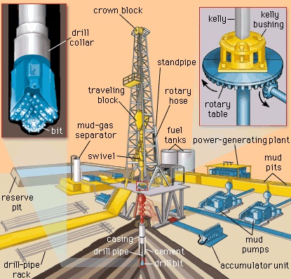
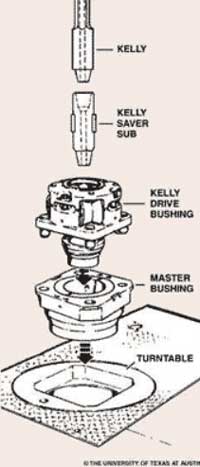
An adapter that serves to connect the rotary table to the kelly. The kelly bushing has an inside diameter profile that matches that of the kelly, usually square or hexagonal. It is connected to the rotary table by four large steel pins that fit into mating holes in the rotary table. The rotary motion from the rotary table is transmitted to the bushing through the pins, and then to the kelly itself through the square or hexagonal flat surfaces between the kelly and the kelly bushing. The kelly then turns the entire drillstring because it is screwed into the top of the drillstring itself. Depth measurements are commonly referenced to the KB, such as 8327 ft KB, meaning 8327 feet below the kelly bushing.

The global kelly drive market was valued at $1.6 billion in 2021, and is projected to reach $2.3 billion by 2031, growing at a CAGR of 3.7% from 2022 to 2031.
Report Key HighlightersThe kelly drive market is consolidated in nature with few players such as NOV Inc., SANY Group, BAUER Maschinen GmbH (Subsidiary of BAUER Group), Jereh Global Development LLC (As a Subsidiary of Jareh Group) and Liebherr-International Deutschland GmbH. that hold significant share of the market.
The study covers in-depth analysis of 16 countries from different regions including North America, Europe, Asia-Pacific, and LAMEA. In addition, country-wise data of every country has been provided for better understanding of kelly drive market dynamics in every country.
A kelly drive is a particular kind of well drilling tool which uses a section of pipe with a polygonal or splined outer surface and feeds it through a rotary table and matching kelly (mating) bushing which have the same shape or splines. The Kelly is a long, four- or six-sided steel bar having a hole bored through the center to allow drilling fluid to pass through. The kelly bushing allows the drill string to be lifted or lowered while it rotates by transferring rotating motion from the rotary table or kelly bushing to the drill string. Crewmembers make up several attachments to the kelly. The attachments include the upper kelly cock, the lower kelly cock (drill pipe safety valve), and the kelly saver sub.
Kelly drilling is one of the most used dry rotary drilling techniques. The kelly drive is used to create large-diameter bored piles (from a size of approx. 500 mm). With the increasing drilling activities is booting the kelly drive market share in coming year. The kelly drive works with almost any kind of rock and soil. According to kelly drive market forecast, the demand for short rotary drilling instruments, such as augers, core barrels, buckets, and specialized drilling tools which are used to move the dirt will be more in the market. The drill rod which is also known as a kelly bar, is a typical component of this drilling technique. The strong kelly bars enables deep drilling and help in boosting the kelly drive market trend in forecast period.
Globally, there has been a surge in oil exploration activity, which is driving the demand for kelly drive in rig and drilling industry. Apart from the pandemic time, a boom in exploration has tripled over the last five years. Kelly drive market analysis showcase the owing to a global boom in exploration of oil reserves, several oil companies are getting into the rig sector. With the ongoing expansion in petroleum products, large oil extraction companies are contracting with drilling equipment manufacturers for the rent and sale of drilling equipment. Oil exploration companies and equipment companies collaborate to provide offshore support services that can increase production. Factor such as oil exploration activities is likely to boost the market for kelly drive in near future.
Advances in technology and equipment have enabled more oil and natural gas to be recovered from the length of each well, improving production and reducing the environmental footprint of energy production. Kelly drive is cheaper however, technology is slow, inefficient, and unsafe as compared to the other technology which are present or coming in the market. These factors may restrain customers from using kelly drive; thus, hampering the market growth.
With combination of seismic surveys and drilling wells, companies are doing the search of oil reserve and deposits beneath the surface of the earth. Exploration projects can be expensive, time-consuming, and risky, drilling a well may cost tens of millions of dollars. Several factors are considered the number of wells to be drilled, recovery method, type of installation to be used, separation systems for the gas & fluids, and how the oil and gas will be transported to a processing facility. High demand for the petroleum products in the market resulting into several new excavations projects in different regions. This factor is anticipated to increase the sales of kelly drive; thus, creating lucrative kelly drive market opportunities.
The kelly drive market is segmented into product type, and region. On the basis of product type, the market is bifurcated into cleaners, braking oil, grease and lubes, degreaser, and others. Region-wise, the market is studied across North America, Europe, Asia-Pacific, and LAMEA.
In 2021, the square kelly segment was the largest revenue generator, and is anticipated to grow at a CAGR of 3.6% during the forecast period. With the increasing horizontal drilling operations result in increasing demand for square kelly in the market. To increase the output from a single well, drilling square kelly equipment are being used frequently in the market. Square Kelly is advantageous for end-users, however equipment can be used for both onshore and offshore drilling operations. Drilling activities are becoming more challenging which are demanding the high quality of kelly equipment. Several oil firms engage in new types of drilling on land, such as horizontal well drilling which covers a significantly larger area under the earth. With the increasing horizontal well drilling creates the opportunity for square kelly segment in global kelly drive market.
In 2021, the kelly bar segment was the largest revenue generator, and is anticipated to grow at a CAGR of 4.0% during the forecast period. With the increasing number of excavation projects and finding of deep oil reserves will increase the demand for kelly bars in the market. Companies are entering into the agreement for the drilling operations which is driving the kelly bars market. Today, reserves are found very deep under the land of sea which require the high strength bars for handling the pressure. Vertical and horizontal drilling activities are increasing which is increasing the demand for different shapes of kelly bars.
The North America kelly drive market size is projected to grow at the highest CAGR during the forecast period. The region is experiencing more drilling activities of oil and gas extraction as the demand for oil-related goods rises worldwide. Kelly drive equipment is particularly helpful for drilling through hard rock and getting to the oil deposits. The Kelly Drive can be used to reduce operational expenses in drilling operations. For field operators and engineers, it ensures long-term project success and a high rate of return.
LAMEA was the second-largest contributor in terms of revenue in the global kelly drive market in 2021, and is anticipated to grow at a CAGR of 3.8% during the forecast period. Accelerated investment across the upstream sector along with crude oil price recovery will foster the drilling activities in the region. Robust growth in petrochemical products demand along with increase in industrial and commercial activities across the developing economies will boost the kelly drive market growth in LAMEA region.
The leading players operating in the global kelly drive market include, NOV Inc., SANY Group, BAUER Maschinen GmbH (Subsidiary of BAUER Group), Jereh Global Development LLC (As a Subsidiary of Jareh Group) and Liebherr-International Deutschland GmbH, Bridges Equipment LTD, Lake Petro., TEXAS INTERNATIONAL OILFIELD TOOLS, LTD, Goldman, Tianhe Oil Group Co. Ltd., XI"AN KINGWELL OILFIELD MACHINERY CO.,LTD, El Didi Group.
It outlines the current Kelly drive market trends and future estimations from 2021 to 2031 to understand the prevailing opportunities and potential investment pockets.
The invasion of Russia has further worsened an already precarious scenario for the energy and drilling markets, notably in Europe. To minimize the possibility of an interruption in Russian oil and gas supply, oil and gas corporations must collaborate with governments. In longer term, the sector needs to increase its adaptability and relevance in a rapidly evolving energy environment. The scenario brought about by the conflict between Russia and Ukraine influences the Kelly Drive market as well. Many projects that were previously underway in the nations are now on hold, and new projects are being delayed, which has slowed the market"s expansion in recent years.

DEN-CON 27 RPH Kelly Bushing is used with Den-Con Pin Drive Master-Casing Bushings for 23" through 49 1/2" Rotary Tables. The 27 RPH has 3 5/16 " diameter drive pins (API) and 25 3/4" pin centers (API) and will handle Kelly sizes 3" to 6" square and 3" to 6" hex.
DEN-CON 20 RPH Kelly Bushing is used with Den-Con Pin Drive Master Casing Bushings for 20 1/2" to 22 1/2" Rotary Tables. The 20 RPH has 2 1/2" diameter drive pins (API) and 23" pin centers (API).
SSB Master Bushings and all Master Bushings having a drive square dimension of 13 9/16" (API). This bushing uses the same roller assemblies, components and wiper assemblies as the 27 RPH. All RH Series Parts & Components Interchange with Varco HD Series Bushing Parts.


 8613371530291