
kelly bushing oil and gas manufacturer
Please send us your inquiry with detail item description or with Model number. If there is no packing demand we take it as our regular exported standard packing. We will offer you an order form for filling. We will recommend you the most suitable model according to information you offered.
We can give you really high quality products with competitive price. We have a better understanding in Chinese market, with us your money will be safe.
Distributor and manufacturer of new and rebuilt oilfield drilling equipment & supplies including mud pumps and parts. Drilling equipment includes swivels, mud pumps, rotary table & draw works. Drilling supplies include tongs, roller chains, valves, drive bushings & rotary heads. Mud pump supplies include duplex & triplex liners & piston & pony rods. Pump parts include crossheads, slides & cranks. Catheads, washpipes, bearings, union pipes, pump heads, pipe nipples, crankshafts, roller chain sprockets & chain & pump drives are available. Capabilities include contractors" equipment repairing services. Drilling equipment & supplies are used in oilrigs.

This website is using a security service to protect itself from online attacks. The action you just performed triggered the security solution. There are several actions that could trigger this block including submitting a certain word or phrase, a SQL command or malformed data.

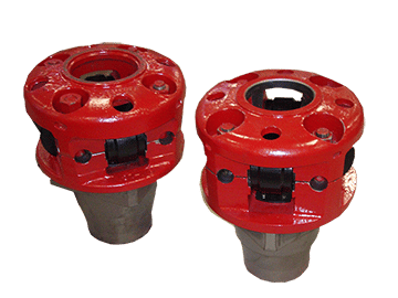
The Kelly Drive Bushing acts as an adapter that serves to connect the rotary table to the Kelly. The Kelly bushing has an inside diameter profile that matches that of the Kelly, usually square or hexagonal. It is connected to the rotary table by four large steel pins that fit into mating holes in the rotary table. The rotary motion from the rotary table is transmitted to the bushing through the pins, and then to the kelly itself through the square or hexagonal flat surfaces between the Kelly and the Kelly drive bushing. The Kelly then turns the entire drillstring because it is screwed into the top of the drillstring itself.
Jiangsu Xinxiang share Co., Ltd was founded in 1994, its predecessor was established in 1955, it‘s located in high-tech industrial concentration zone of Nantong City, Jiangsu Province; near to a new developing international deep-water port Yangkou Port which commitment to ship 200,000 tons goods; world famous modern city Shanghai is only 2.5 hours away from it by car; company registered capital is 60,000,000 RMB, the total assets is 119.85 million RMB, it covers an area of 160,000 square meters and currently over 500 employees. Jiangsu Xinxiang Share Co., Ltd is "self-import and export enterprise", "private technology enterprises in Jiangsu Province", "high-tech enterprises in Jiangsu Province", it is top ten companies of the first national large and medium-sized industrial enterprises in independent innovation capacity of the industry; it accessed to API7, 7K, 8A, 8C, and has the right to use the logo, and also passed the ISO9001:2000 quality system certification in the earlier stage within the same industry.

Jiangsu Saifu Petrol- Machinery Co., Ltd is a company with high and new technology engaged in developing, manufacturing and marketing of drilling tools and spare parts. Founded in August 2000. After several years of research and innovation, the company has become an oil drilling tools manufacturing enterprise with certain manufacturing capacity.
Company covers an area of more than 40,000 square meters, registered capital 50.8 million Yuan. And its main products include manual tongs series, slips series, elevators series, elevator links series, bushing series, casing spider series and pneumatic slips series etc. There are 12 products won the national utility model patent product, one invention patent products, five high-tech products, 2 in Nantong famous brand product.
Our products have been sold to various domestic oilfields and exported to Europe, America, Middle East, Central Asia, North Africa and South-East Asia and other overseas regions. Equipped with excellent equipment, strong technique force and completed test facilities, the company constantly innovate and expand market. Now the company has become a first-level supply member of Chinese Petroleum & Natural Gas Consortium, as well as the member of China Petrochemical Material Resources Market. We have obtained the Production License issued by the nation. Strict quality control has allowed us to gain the ISO9001-2008 certificate of quality management system, ISO1400:2004 environment management system certification and GB/T28001-2011 occupational health and safety management system certification and have the right to use API Spec 7K, 8C monogram. Since 2004 and has become a network members Petrochina, CNOOC, Sinopec level, won the "private technology enterprises in Jiangsu province" title, and won the "enterprise credit AAA level" and Nantong "contract" AAA level enterprise title Exploring the way forward in practice and surpassing self in innovation, our ‘Zero Defect and Zero Distance’ service purpose is bringing us more and more business partners.
We believe that our company will usher in a new takeoff through the joint effort of all members of Saifu and love for the cause of oil drilling tools in the near future.

An adapter that serves to connect the rotary table to the kelly. The kelly bushing has an inside diameter profile that matches that of the kelly, usually square or hexagonal. It is connected to the rotary table by four large steel pins that fit into mating holes in the rotary table. The rotary motion from the rotary table is transmitted to the bushing through the pins, and then to the kelly itself through the square or hexagonal flat surfaces between the kelly and the kelly bushing. The kelly then turns the entire drillstring because it is screwed into the top of the drillstring itself. Depth measurements are commonly referenced to the KB, such as 8327 ft KB, meaning 8327 feet below the kelly bushing.

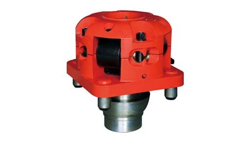
The JOTKB MODEL 27 PDHD OR 20 PDHD are developed for pin drive master bushing for rotary table sizes from 27-1/2" to 49-1/2" having 25-3/4" and 23" dia pin center. This unit is used for heavy duty drilling operations and high torque conditions on off shore as well as on shore drilling operations, and handle Kelly sizes from 3" to 6" Square or Hexagonal.

This website is using a security service to protect itself from online attacks. The action you just performed triggered the security solution. There are several actions that could trigger this block including submitting a certain word or phrase, a SQL command or malformed data.

Priority date (The priority date is an assumption and is not a legal conclusion. Google has not performed a legal analysis and makes no representation as to the accuracy of the date listed.)
Radial clamping/sealing system and drilling system provided therewith for (semi)-continuous drilling a borehole, drilling rig comprising such system, and method there for.

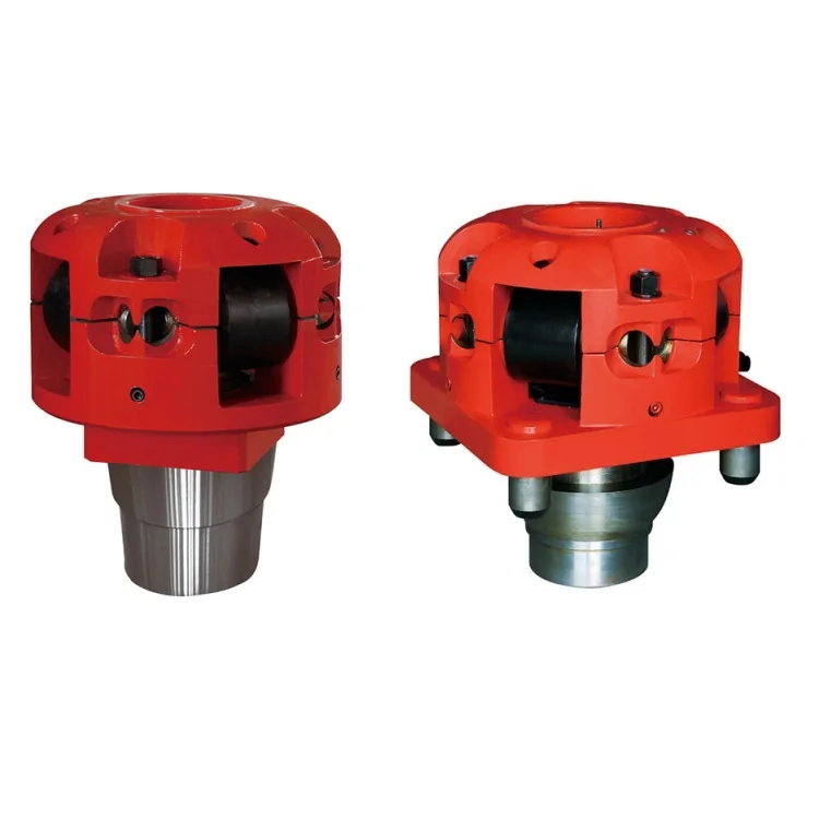
Our company produces all kinds of bushings, including casing bushings, kelly bushings and so on. Casing bushings are manufactured with high-strength heat treated steel. They"re specially designed to work with NOV rotary equipment and handling tools. With interchangeable insert bowls, these casing bushings can accommodate casing sizes from 16 inches up to 42 inches in diameter. There are three standard types for choice. Models CU and CUL are solid bushings, while the Model CB is a split bushing. These bushings are available for 17 1/2 in to 49 1/2 in rotary tables. In the operation, casing bushings are inserted directly into the rotary table to ensure that the casing runs perfectly with the center of the hole.
As a professional China casing bushings, kelly bushings and other oil drilling tools manufacturer, Jiangsu Kayson Petrol- Machinery Co., Ltd becomes a first-level supply member of Chinese Petroleum & Natural Gas Consortium. At the same time, it"s also the member of China Petrochemical Material Resources Market. And it has achieved the right for products import and export.

Just like no two people are alike, neither are two wells. It doesn’t matter if the wells are located in the same area, utilize the same equipment, or if they are drilled into with the same oil-bearing formation; the outcomes of the drilling procedure relies on a wide variety of variables. This can include: people, equipment, company procedures, and more; and in order to be a successful lease pumper, you will need to understand these eight important areas.
Every signed oil well drilling contract includes some form of conditions and agreements. For example, the drilling rig contractor will agree to a specific drilling depth, financial obligations, or where the well will be drilled. Once everything has been agreed upon, the drilling rig will be moved in to prepare for drilling. This is most commonly referred to as the MIRU, or the “Move In and Rig Up”; and in most cases, will include drilling with a jackknife rig instead of the derricks that are built in place. Other important personnel often comprise of:
Typically the company representative is one of the senior members of the crew (such as the tool pusher), the owner of the company (this generally occurs in small oil companies.), or another official representative for the company. Since the company pays the full cost of drilling and owns the new well once completed, the company representative will oversea every operational aspect from building roads to installation of the wellhead. In many cases, the company representative also makes the final decisions regarding the formation tests.
Commonly referred to as the derrick man, a derrick worker cannot be afraid of heights. This position requires working high above the floor, and is used during regular operations to help when the pipe is being pulled or run. In many of the modern rigs, a rack will vertically hold various sections of drill pipe along the side of the derrick. Each is then added to the drilling string as the bit makes it way deeper and deeper into the ground.
One of the common duties of derrick workers is to add (or remove) sections of pipe from the drill string. During drilling, the pipe is added the deeper into the ground they drill; while sections are removed from the drill string and pulled out of the ground once the drilling has been complete. Sections of pipe are also removed for replacement, or to deal with any drilling issues.
The rig crew typically consists of four to five people, with the driller in charge of the group. He/she will generally operate the draw works (a structure made of cables and pulleys used to run the pipe into the well), and often performs the tool pusher’s duties when they are away or off work.
While running and pulling pipe, there are always two floor workers. These two personal are generally referred to as either roughnecks or floor hands, with the more experienced worker being referred to as the lead. The lead operates the lead tong, while the other floor worker operates the back-up tong (or back-up). In most cases, these workers are the most inexperienced members of the rig crew.
In a five person rig crew, the fifth individual is commonly referred to as the motor worker (also known as the motor man). The motor man is one of the most experienced workers, and will often relieve the driller during times off. He/she may also be required to catch drilling samples.
Every drilling company provides a supervisor for the rig during the drilling of the well. While more and more crews have taken on titles like drilling engineer, production engineer, or other comparable titles; at one point in time, this individual was only referred to as the tool pusher.
The tool pusher is in charge of both the drilling rig, and every moving part on that rig. It is their job to purchase and rig supplies, supervise the rig personnel, and to oversea all the drilling procedures. Due to today’s technological advances making communicating easier, tool pushers may also be in charge of more than one rig at a time; and therefore, may not always be present at a specific location. Due to the vital importance of having this type of supervision required for around-the-clock drilling operations, the tool pusher is often supplied some sort of small domicile (ex. small mobile home) at the well site. This allows them the ability to remain onsite for days at a time in the event any problems arise.
While the rig is moved onto the lease for drilling a new well, a lease pumper can often be required to handle operation related duties. For example, most drilling rigs utilize anywhere from two to four steel mud pits. These pits (generally lined with some form of plastic liner) are used to hold any excess fluids or drilling cuttings; with the first pit will have a shale shaker built on the top to permit the drilling mud to fall through the screen.
During drilling operations, lease pumpers are often responsible for looking out for the landowner’s interests, especially for contracted drilling. This includes making sure the mud pit is properly fenced. Otherwise, the livestock could try to get into the pit to drink the water, or eat any trash or greasy rags left behind. However, due to the fact mud pits can take several weeks or even months to dry out enough to be leveled out; this duty doesn’t end once the hole is finished. In fact, after the rig is no longer active, the landowner will still anticipate the lease pumper to preserve a clean and well-fenced pit to protect their livestock from harm.
Another common responsibility of lease pumpers is maintaining the well records, with one of the most important sets being the downhole measurements. These measurements document the dimensions of every single section of pipe used in the well, and are vital to knowing the size of pumps, tools, or other supplies required to pass through or be used on the pipe (including any required components to complete the installation).
Tubing – Refers to the moveable strings of pipe that can be easily pulled and run back in whenever working the well. The tubing is located inside of the casing, and is measured by the outside diameter.
In order to accurately determine the location of the perforations, the depth of the well, or various other vital features to the production; downhole measurements must be captured accurately. Each measurement is made to the nearest one hundredth of a foot (all rig tapes use the same measurement system) to allow numbers to easily be used by a conventional calculator. This would be equivalent to taking each foot and dividing it into ten equal parts, and then taking each of those sections and dividing them into ten more parts. For example, if you have three pipe lengths measuring: 20 feet 3/32″, 20; 4 5/16″, and 19′ 9 1/4″; using this system, your measurements would be: 20.09, 20.36, and 19.77.
As the crew drills the well, the distances are calculated starting from the top of kelly bushing (refers to the sliding bushing located on the drilling rig floor on top of the rotary table that permits the drill kelly to go down through it when the pipe is turning and the hole is drilled.
Once the casing pipe is permanently cemented into the hole (or set) and either the braiden head or wellhead installed, the measurements from the top of the wellhead to the top of the kelly bushing are calculated and subtracted from all drilling records. This allows precise well records for once the drilling rig is no longer there.
Since the majority of the water we drink comes from underground fresh water reservoirs, one of the most important considerations in drilling a new well is protecting any fresh water areas. Therefore, the string of surface casing bottom has to properly extend below the fresh water zones. The surface hole must also be drilled to a depth deep enough for it to pass through any loose materials you may encounter until the stable rock is encountered, and the surface pipe is set.
Below the surface casing is placed (aka ‘run in the hole’), it is diligently inspected and measured; and often times, each of the couplings are welded to help prevent any future leaks from occurring. Once complete, the scratchers and centralizers (bow shaped strips of steel used to hold the pipe in place away from the walls and in the center of the hole) are installed on the pipe (See Figure 2).
Scratchers are used to help the cement to be able to bond the pipe and the walls of the hold. Their job is to remove the caked-on drilling mud, and it is done by raising and lowering the pipe several times into the hole to allow the scraper to loosen the material. As the crew pumps the cement down into the hole (going through the casing) and out the bottom, it will rise up towards the surface on the outside of the casing creating a good cemented bond all the way around the entire pipe from the bottom to the surface. The pipe is then left in place even when the well is plugged.
Depending upon the depth of the well, some may require a second string of pipe above the production reservoir. (This section is also cemented into place.) Often times, this second string of casing is installed to correct any adverse hole conditions. These reasons could include: gas, heaving, high pressure, lost circulation zones, or sloughing.
Each and every additional string of casing placed in the hole will use a smaller bit. This allows for the new bit to go inside the new casing and to drill out through the bottom. In most cases, it will go all the way to the reservoir; yet in deeper wells, rig crews may install string of casings comprising of each string of casing successively getting smaller in diameter. This is typically completed for financial reasons, or due to the physical limits of the casing string.
To begin, a moderately large casing is used from the surface and partially down into the hole; following it with a slightly smaller string of drill pipe and bit. At the bottom of each string of casing, a casing hanger is installed to permit the next section of pipe to be lowered into place through the current section, before it is firmly attached and cemented permanently into place. As the crew runs the casing, they may also use a technique known as floating the pipe in; which requires filling the casing with drilling mud to prevent it from collapsing under the extremely high external pressure.
When a drilling break (an indicator the formation is more porous and cause the drilling bit to cut into the earth in an abrupt increase) occurs one of the more imperative decisions the drilling supervisor must make is determining how to proceed. Often times, this permeable layer can hold different hydrocarbons (ex. natural gas, crude oil). Thankfully by taking everything into consideration (ex. the location and/or distance to the bottom of the well, how fast the crew is operating the pump, the amount of space outside of the drill pipe, etc.) the crew and/or supervisor can determine exactly how long it will be before the drilling break zone cuttings are able to reach the surface.
Once these cuttings arrive, a crew member will catch samples and use these to test under a black light (aka ultraviolet light). If crude oil is present, the black light will cause the sample to glow. Unfortunately, high mud pressure can prevent a good cutting sample from reaching the surface. To overcome this issue, one answer is to perform drill stem testing.
Typically time and/or allowances are allotted in the contract to provide the rig crew time to run the pipe and cement it into place. Generally during any time the rig stops drilling, the lease operator (or production company) will compensate the crew by paying by the hour, or through some other appropriate amount of compensation for the rig crew during any time spent cementing, running pipe, and/or waiting for the cement to set (drilling reports often refer to this as waiting on cement).
As with any type of drilling, as the bit is used the tooth sharpness and diameter will slowly wear away; and when the bit diameter shrinks, so does the diameter of the hole being drilled. To avoid this issue, a reamer is placed right behind the bit. This sequence of rolling cones rotates is the bit turns, and widens the hole slightly larger. Typically this will take one time of reaming the hole to be sufficient.
Due to factors like formation density, uneven drill bit wear, drill pipe flexing, and various other situations that can cause the hole to deviate from the its true vertical depth(the vertical distance from the well to the surface); you typically are unable to drill a straight hole to the oil reservoir. Nonetheless, the hole is still generally viable for oil production.
For the best results when drilling the hole, an incessant series of decisions will be used to adjust the drilling method. This includes considering all aspects from getting the best life and performance out of your drilling bits, to the location of the hole, to what choices you should make to ensure good drilling progress. Typically there are two main ways to control these types of factors:
In most cases, the maximum penetration rate (and the straight hole) are maintained by applying the correct bit, drill pipe weight, and bit RPM. You need a good balance of these factors to determine the proper adjustments for your conditions (such as formation density or any hole depth changes).
Any formation the drill bit comes across that is not horizontal, tends to climb uphill. This can easily be solved by applying more drill collars on top of the reamer. The extra drill collars will add more weigh, and thus make the pipe more inflexible. Sadly, drill collars will not solve all your drilling issues. For instance, another common issue is when the drill bit gets stuck in the grooves (also referred to as key seats) located on the sides of the hole.
Key seats are created when the drill pipe bends under the high pressures and rubs along the sides of the hole. The connections (the lined ends of the drill pipe) are generally larger in diameter than the drill pipe’s body (or tube). Since these connections are larger than the rest of the pipe’s diameter, it is common to get stuck in the key seats. This is especially true when the rig crew begins to remove the drill bit back out of the hole.
Formations never have the same density throughout the entire distance to the production zone; and because of this, bit wear, and flexes in the drill pipe, it is very rare the rig crew will experience a hole that goes straight down. In fact, most cases will generally have a twisted profile like a corkscrew; and due to this, the tubing string is likely to rub against the casing when it comes into contact with the various bends. This rubbing will eventually cause the tubing or casing to wear, and in turn, produces even more problems for drilling operations; such as:

A 27-year-old gas drilling rig worker died on May 23, 2003 from blunt force trauma to the head, neck, and chest during a cleanout operation at the well. At the time of the incident, the victim was working within eight feet of the kelly on the drilling rig floor. Compressed air was used to blow out the conductor pipe, but due to a lack of communication, the compressor was turned on before the valves were prepared to control the flow of debris out of the hole. The excess pressure caused the kelly bushing, drillpipe slips, and debris to be blown out of the rotary table. The victim was struck by these objects and was pronounced dead on arrival to the hospital.
Ensure that all employees are trained properly and possess the skills necessary to recognize and control hazards for all operations in which they participate.
A 27-year-old gas drilling rig worker died on May 23, 2003 from blunt force trauma to the head, neck, and chest after he was struck by the kelly bushing and drillpipe slips. OKFACE investigators reviewed the death certificate, related local news articles, and reports from the sheriff’s office, Medical Examiner, Occupational Safety and Health Administration (OSHA),
and emergency medical services (EMS). Interviews were conducted with company officials, including safety representatives, at the company headquarters on August 19, 2003.
The drilling company that employed the decedent had been in business for 33 years and, at the time of the incident, employed 140 individuals. The victim had five years of experience in drilling operations and had worked for this drilling company off and on over that five-year period. However, during this time of employment, he had been working for the employer for only three days. At the time of the incident, the decedent was part of a five-person crew that was working at a gas well site, which had been in operation for three days (Figure 1). The victim was fatally injured during a cleanout operation. The cleanout process is a normal part of drilling operations and involves blowing out mud, water, and debris by pressurizing the well shaft with either air or liquid as the standard cleaning media. The victim had performed the cleanout process many times in the past.
The company did have a comprehensive written safety program in place at the time of the incident. The victim had received formal company safety training and informal on-the-job training specifically relating to cleanout operations. Safety meetings were held regularly, and levels of training were measured by employee testing and demonstration. Two of the five workers at the site had recently joined the crew from other drilling companies; however, they each had years of experience in oil and gas drilling.
At the time of the incident, the rig floor and working surfaces were level and dry; the weather was warm with light to no wind. The victim was working with four other crew members on a gas drilling rig, wearing the necessary personal protective equipment (e.g., steel toe boots, hard hat, eye protection). Prior to the incident, the decedent was assigned the task of driller and was asked to find the bottom of the conductor hole with the kelly (Figure 2). The kelly is used to transmit power (rotary motion) from the rotary table and kelly bushing to the drillstring (Table 1). After unlatching the brake handle, the driller allowed the kelly to free fall to the bottom. The uncontrolled fall caused the kelly to become jammed with debris, such as water, mud, and other material, that had collected in the conductor hole since the time it was originally drilled for the well. As a result, a cleanout operation became necessary. Cleanout procedures involving air or mud drilling fluid are acceptable norms in the oil and gas drilling industry; however, drilling fluid is more commonly used than compressed air.
a long square or hexagonal steel bar with a hole drilled through the middle for a fluid path; goes through the kelly bushing, which is driven by the rotary table
After the kelly became jammed, a senior driller was assigned to take over the brake handle and kelly; however, the decedent remained approximately eight feet away on the rig floor. A newly hired, yet experienced, derrickman had the job of running the air compressor. While the drillers were switching positions, the derrickman realized that he had not started that particular type of compressor in quite some time and left the rig floor to seek help from another driller onsite.
In normal cleanout operation procedures, certain valves are closed prior to turning on the compressed air, which allows control over the flow of debris out of the hole and into a catch pond. Once the valves are prepared, the driller indicates to the derrickman that the area is ready for the compressed air. At some point between the senior driller preparing for cleanout and the derrickman leaving the floor to turn on the air compressor, there was a lack of communication and the air compressor was activated without the senior driller’s knowledge, prior to the prescribed valves being shut. After starting the air compressor, the derrickman returned to the rig floor and, as he walked to his next assignment, the rotary table erupted. The pressure normally used to complete the cleanout work is a minimum of 20 pounds per square inch. Within minutes, the kelly had pressurized well beyond this point to 150 pounds per square inch. The victim, who was still on the rig floor in close proximity to the kelly, was also unaware that the air compressor had been turned on. The compressed air, at full pressure with no valves closed to control or direct the flow, blew the kelly bushing, drillpipe slips, and debris out of the rotary table; all of which struck and landed on the victim.
The victim was the only crew member injured by the flying debris and equipment. The victim was pulled away from the hazardous area, laid down, and kept calm. There was some initial confusion over whom to call for help, which caused a lack of quick medical response. Apparently no emergency numbers were posted on-site; although, a cell phone was available, there may have been some trouble getting through. One of the crew members went to the nearest farmhouse to find out how to call local EMS, while another was sent out to the road to direct first responders. EMS arrived at the scene approximately 30 minutes after the incident and loaded the victim for transport to the hospital. The victim was pronounced dead on arrival to the hospital, which was approximately 20 miles away.
Discussion: Employers should develop, implement, and enforce standard operating practices and procedures for all drilling operations to safeguard against unexpected energization or startup of equipment/machinery, or hazardous energy release during servicing and maintenance. These written practices and procedures should be reviewed at least annually. In this incident, standard operating procedures for performing cleanout, and training to those procedures, were needed to help monitor air and hydraulic pressure and control pumps and compressors. Had a standard written operating procedure been in place and complied with by the crew, this incident may have been prevented. While using compressed air is a normal cleanout practice, the area around the rotary table becomes highly hazardous during the procedure and requires certain precautions, such as following each step in order, knowing where debris will go before the air is started, and clearing crew members from dangerous areas. With enforced, documented procedures, the chances of inadvertent hazardous energy release are reduced.
Recommendation #2: Employers should monitor all job tasks to ensure that employees are not directly positioned in areas that are subject to flying parts, debris, and other hazards.
Discussion: The employer and designated site supervisors should monitor the site for hazardous situations and non-compliance. Any deviations from written job procedures or safety standards, or any unsafe situations that arise from site-specific work, should be addressed by management and corrected immediately. All employees should take steps to address unsafe work procedures and to eliminate them by accepted means of control or modification, including, but not limited to, engineering controls, work practice controls, and the use of personal protective equipment. Employees should be aware of how they are positioned at all times to avoid standing, sitting, or working in hazardous zones.
Recommendation #3: Employers should ensure that all employees are trained properly and possess the skills necessary to recognize and control hazards for all operations in which they participate.
Discussion: Employees should be trained thoroughly and formally on the standard operating procedures that are relevant to their duties and assignments. In addition, employers should consider thorough skill evaluations or screening for functional skills prior to hire or work assignment. For operations, such as performing cleanout on a drilling rig, the potential hazards of blowouts during the operation should be addressed, as well as ways to minimize or eliminate the hazards. In addition, training should emphasize the importance of establishing and maintaining good communication between all crew members while performing all work procedures. Documentation of the training should be kept on file with the company, and periodic retraining of employees should be done. Retraining should always occur when there are changes in the equipment, processes, or hazards present. Oil and gas industries should consider consulting sources such as publications from the International Association of Drilling Contractors (IADC; http://www.iadc.org/external icon) (Link Updated 4/1/2013) and OSHA’s Oil and Gas Well Drilling and Servicing eTool (https://www.osha.gov/SLTC/etools/oilandgas/ general_safety/general_safety.htmlexternal icon) for information on safety and training.
Recommendation #4: Employers should develop and utilize a written emergency action plan and should train employees on site-specific emergency response plans.
Discussion: The emergency action plan should be in written form and include all necessary steps to take when an emergency occurs. The plan should contain steps for providing emergency first aid and cardiopulmonary resuscitation (CPR), the phone numbers for all emergency providers and appropriate company officials, and the proper documentation forms to complete following an emergency. The plan should also address fire evacuation and prevention, severe weather procedures, and workplace violence and safety. Every employee should be trained annually on the company’s emergency action plan. Information should be provided on the scope, purpose, and application of the plan. Site-specific information (e.g., severe weather shelters, fire evacuation plan, location of nearest medical care facilities, and pertinent contact phone numbers) should be given to or posted for employees each time a rig is moved. Employees should know where copies of site-specific plans are kept and who to notify if the plans are not readily available. In addition, remote jobsites should have cell phones, two-way radios, or other reliable means of quick communication in the event of an emergency.
Occupational Safety and Health Administration. Oil and Gas Well Drilling and Servicing eTool. (https://www.osha.gov/SLTC/etools/oilandgas/general_safety/general_safety.htmlexternal icon)
The Oklahoma Fatality Assessment and Control Evaluation (OKFACE) is an occupational fatality surveillance project to determine the epidemiology of all fatal work-related injuries and identify and recommend prevention strategies. FACE is a research program of the National Institute for Occupational Safety and Health (NIOSH), Division of Safety Research.
These fatality investigations serve to prevent fatal work-related injuries in the future by studying the work environment, the worker, the task the worker was performing, the tools the worker was using, the energy exchange resulting in injury, and the role of management in controlling how these factors interact.
To contact Oklahoma State FACE program personnel regarding State-based FACE reports, please use information listed on the Contact Sheet on the NIOSH FACE website. Please contact In-house FACE program personnel regarding In-house FACE reports and to gain assistance when State-FACE program personnel cannot be reached.

v: 1. to assemble and join parts to form a complete unit (for example, to make up a string of drill pipe). 2. to screw together two threaded pieces. Compare break out. 3. to mix or prepare (for example, to make up a tank of mud). 4. to compensate for (for example, to make up for lost time).
n: a device that is attached to the shaft of the drawworks and used as a power source for making up joints of pipe. It is usually located on the driller’s side of the drawworks. Also called spinning cathead.
n: a device that fits into the rotary table to accommodate the slips and drive the kelly bushing so that the rotating motion of the rotary table can be transmitted to the kelly.
n: a drilling rig in which the source of power is one or more internal-combustion engines and in which the power is distributed to rig components through mechanical devices (such as chains, sprockets, clutches, and shafts). Also called a power rig. Compare electric rig.
n: a method of enhanced recovery in which various hydrocarbon solvents or gases (such as propane, LPG, natural gas, carbon dioxide, or a mixture thereof) are injected into the reservoir to reduce interfacial forces between oil and water in the pore channels and thus displace oil from the reservoir rock. See chemical flooding, gas injection.
n: an employee of a drilling fluid supply company whose duty it is to test and maintain the drilling mud properties that are specified by the operator.
n: the recording of information derived from examination and analysis of formation cuttings made by the bit and of mud circulated out of the hole. A portion of the mud is diverted through a gas-detecting device. Cuttings brought up by the mud are examined under ultraviolet light to detect the presence of oil or gas. Mud logging is often carried out in a portable laboratory set up at the well site.
n: an arrangement for producing a well in which one wellbore penetrates two or more petroleum-bearing formations. In one type, multiple tubing strings are suspended side by side in the production casing string, each a different length and each packed to prevent the commingling of different reservoir fluids. Each reservoir is then produced through its own tubing string. Alternatively, a small diameter production casing string may be provided for each reservoir, as in multiple miniaturized or multiple tubingless completions. See dual completion.


 8613371530291