
rotary kelly hose free sample

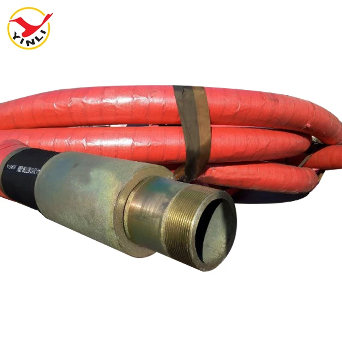
Flexible drilling rubber hoses play an important role in petroleum extraction. They should suffer high operating pressure, extreme operating temperature, abrasion and other inferior elements. Our special compounded synthetic rubber has been proven an effective and economical way to reject these problems. All our oilfield drill hoses are manufactured as API 7K or other related specifications.
Steel cable reinforcement loads most working pressure up to 15,000psi. The wires are usually zinc-plating or copper platting to improve steel wire resistant against rust and corrosion. Due to the thick reinforcement, the hoses should be handled or stored in correct way to avoid kicking or crushing. They will substantially decrease their rated operating pressure.
Rotary hose, Kelly hose, cement hose, mud hose, jumper hose and vibrator hose and choke & kill hoses are the most popular oilfield rubber hoses. They convey high-pressure drilling fluid from one place to another. Many end fittings are provided to satisfy different applications. Most end fittings are made according to API standards. Special order is also available.
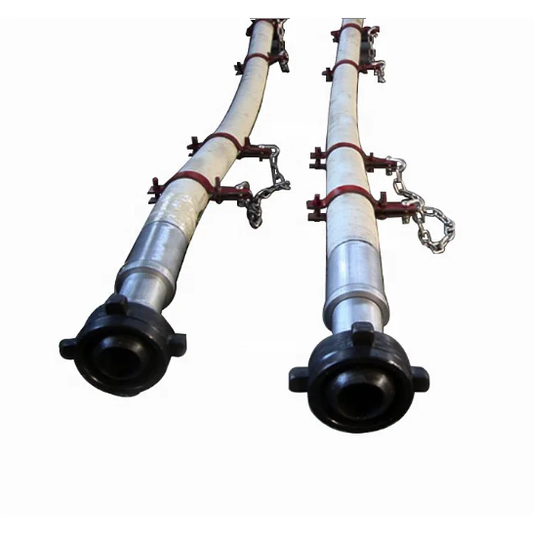
In an effort to prevent kinking, binding or snagging of kelly spinner hoses during the raising and lowering of said hoses together with a rotary hose in oil drilling rigs, it is known to tape the kelly spinner hoses to the rotary hose which provides the drilling fluid. There is a serious defect in this arrangement since the kelly spinner hoses and the rotary hose are used independently in the sense that they are under different pressures at different times. Thus, for example, the kelly spinner hoses will not be pressurized with air when the rotary hose is pressurized with the drilling fluid. Since the pressurization of the rotary hose is typically in the range of from four thousand to five thousand psi, the hose is substantially elongated typically from about six to ten inches. This results in substantial straining of the kelly hoses. By the same token the kelly hoses when they are pressurized, are strained due to the fact they are prevented from moving relative to the rotary hose. Further, these strains have a tendency to rupture the tape leaving the kelly spinner hoses free to move independently which is a serious hazard for rig personnel since, if one of these hoses ruptures or separates from the fittings attached to the kelly swivel it will whip violently incident to the exhausting of the high pressure air through the rupture or the freed end of the hose. All of these problems have been solved by this invention by providing guides for the kelly hoses which attach to the rotary hose and permit the kelly hose and the rotary hose to move freely axially relative to each other while preventing kinking, binding and snagging while the hoses are raised and lowered. In addition, the invention facilitates the installing and disconnecting the kelly spinner hoses. The life expectancy of the kelly spinner hoses is increased, reducing down time.
The invention is a safety guide for kelly spinner hoses in drilling rigs and a plurality of said safety guides in combination with kelly hoses and a rotary hose. Each safety guide comprises a pair of opposed rings, each adapted to receive and guide a kelly spinner hose, and a device for securing the rings to a rotary hose substantially in a plane perpendicular to the axis of the rotary hose. Advantageously, each ring has a rigid integral loop member and the securing device comprises a flexible band passing through said loop members. It is preferred to secure the band to the rotary hose with a buckle. In the combination, a plurality of the safety guides are spaced along the length of the rotary hose, preferably substantially equidistant.
FIG. 3 is an elevational view showing a guide in accordance with the invention in association with the kelly spinner hoses and the rotary hose of the rig of FIG. 1;
Referring to FIG. 1, an oil drilling rig 2 has a derrick 4 having a hoist 6 provided with a lifting hook 8 which is adapted to engage a ring 10 (FIG. 2) attached to a swivel fitting 12 which in turn is connected to a kelly indicated at 16 adapted to connect with a rotary table 18 (FIG. 1). A kelly spinner 20 rotates kelly 16 and is supported by a turn buckle 22 connected to swivel fitting 12.
A rotary hose 26 is connected by a fitting indicated at 28 (FIG. 2) to swivel fitting 12. Rotary hose 26 is connected to a stand pipe 30 which is adapted to deliver a drilling fluid as indicated at 32 (FIG. 1). Kelly spinner hoses 40 and 42 are connected to Kelly spinner 20 and are respectively connected to their delivery pipes 44 and 46 as indicated at 48 and 50 (separated for clarity in FIG. 1, but actually close to fitting 32).
Kelly spinner hoses 40 and 42 are each guided by a plurality of guides 60 in accordance with the invention which are substantially equally spaced along the length of rotary hose 26.
As best seen in FIG. 4, each guide 60 has a pair of opposed guide rings 62 and 64 through which hoses 40 and 42 pass respectively. Guide ring 62 has an integral member loop member 66 which runs substantially perpendicular to a plane through ring 62 and has a relatively narrow opening 68 (FIG. 3). Likewise, guide ring 64 has an integral loop member 72 running substantially perpendicular to the plane of ring 64 and having a relatively narrow opening 74.
A band 78 passes through openings 68 and 74 and around rotary hose 26 to which it is tightly secured by buckle 80. Buckle 80 has a flat plate 82 to which is secured a loop 84 (FIG. 5) and outwardly and downwardly extending opposed fingers 86, 86. The inner end 90 of band 78 passes between plate 82 and loop 84 and between back plate 82 and fingers 86, 86 and is bent back on itself inside of plate 82. Band 78 is then run around rotary hose 26 twice passing through loop members 66 and 72 and between plate 82 and both loop 84 and fingers 86 twice to form two loops indicated at 96 and 98 in FIG. 4 and then outer end 92 is turned back on itself over loop 84 and passed inside of fingers 86, 86 thus securing the rings 62 and 64 to rotary hose 26 (FIGS. 4 and 5).
The guides 60 are substantially equally spaced along hose 26 advantageously at a distance of from about 96 to about 144 inches. It will be seen that since the kelly spinner hoses 40 and 42 are loosely received in guide rings 62 and 64 each of the hoses 40, 42 and 26 can move freely axially relative to each other. Should one of the hoses 40 or 42 become detached from the kelly spinner it will be prevented from dangerous whipping. While a variety of materials may be used to make the guides 60, it is preferred to employ stainless steel for all the parts. The guide rings 62 and 64 are conveniently welded to loop members 66 and 72 as indicated at 100 and 102 respectively in FIGS. 3 and 4.

n: the area immediately around the rotary table and extending to each corner of the derrick or mast—that is, the area immediately above the substructure on which the rotary table, and so forth rest.
n: the machine used to impart rotational power to the drill stem while permitting vertical movement of the pipe for rotary drilling. Modern rotary machines have a special component, the rotary or master bushing, to turn the kelly bushing, which permits vertical movement of the kelly while the stem is turning.
n: a worker on a drilling or workover rig, subordinate to the driller, whose primary work station is on the rig floor. Sometimes called floorhand, floorman, rig crew member, or roughneck.
n: a length of pipe whose bottom edge is serrated or dressed with a hard cutting material and that is run into the wellbore around the outside of stuck casing, pipe, or tubing to mill away the obstruction.
n: a strong but relatively lightweight device used on some rigs that employ a top drive to rotate the bit. Although a conventional rotary table is not required to rotate the bit on such rigs, crew members must still have a place to set the slips to suspend the drill string in the hole when tripping or making a connection. A rotary support table provides such a place but does not include all the rotary machinery required in a regular rotary table.
Rotary drilling rigs for forming boreholes require a rotary table centrally positioned on the floor of the drilling rig. The rotary table has a rotating center which receives a kelly bushing therein which imparts rotation into a kelly. The kelly is free to slide within the bushing and has a string of drill pipe connected at the lower end and a swivel at the upper end thereof.
The rotating table center and kelly bushing usually have bolt heads, fastener heads, and various other protrusions as well as various different indentions formed thereon. This is especially so on the older rotary drilling rigs.
The roughnecks working on the confined floor of a drilling rig must handle cables, chains, ropes, water hoses, and various hand and power tools. All of this is carried out in an extremely small floor area and from time to time a tool will inadvertently fall onto the rotating table center and centrifugal force throws the tool outwardly where it may strike a workman.
Accordingly, it is advantageous and highly desirable to encapsulate the rotary table of a drilling rig so as to isolate this dangerous area from the workmen so that should one accidently drop anything on the rig floor, it cannot possibly be caught in the rotating center.
This invention relates to drilling rig safety equipment, and specifically to a guard for a rotary table and a kelly, such as may be found on a rotary drilling rig or a workover unit. The guard of this invention has a lower end in the form of a flat circular show member from which there upwardly extends a wall member. The upper end of the wall member terminates at a bearing means. The bearing means is spaced from and concentrically arranged respective to the shoe, and has a rotatable part which slidably receives a marginal length of the kelly therethrough. The rotating kelly rotates the rotatable part of the bearing while the remainder of the bearing means remains stationary. Hence, the guard encapsulates the most dangerous parts of the rotary table and kelly and prevents extraneous items from falling into contact therewith.
Another object of the present invention is to provide apparatus which will prevent extraneous members from contacting the rotating parts associated with a rotary table of a drilling rig or the like.
Another and still further object of this invention is to disclose and provide a safety structure which prevents contact of anything with the dangerous rotating parts of a rotary table.
A still further object of this invention is to provide a guard in the form of a non-rotating safety shield located about the rotating parts of a rotary table so that nothing can inadvertently contact the rotating parts.
These and various other objects and advantages of the invention will become readily apparent to those skilled in the art upon reading the following detailed description and claims and by referring to the accompanying drawings.
This invention relates to a rotary table and kelly bushing guard for use in conjunction with a drilling rig, workover rig, or the like. In drilling boreholes, the massive rotary table, kelly, and kelly bushing are exposed in the center of the greatest activity of the drilling operation. From time to time, a roughneck will inadvertently catch a hose or chain or the like in the rotating mass, whereupon he often is violently thrown into the apparatus and fatally injured. Accordingly, the apparatus of the present invention isolates this dangerous mechanism from the surrounding area so that extraneous material cannot inadvertently come into contact therewith.
As seen in FIG. 1, a derrick floor 10 of a rotary drilling rig includes the non-rotating, circumferentially extending floor area 12 which overlies a rotary mechanism 14. The mechanism imparts rotation into a kelly bushing 16 by means of a drive sprocket 18 connected to the end of a pinion shaft of the rotary device. The kelly 20 is slidably received in a telescoping manner through the kelly bushing 16 in the usual manner, while drive mechanism 22 removably receives the kelly bushing 16 in the usual manner. As mechanism 16, 20, and 22 rotate respective to the fixed floor 12, there is a danger area 24" which must be avoided. There is always the grave danger that someone will somehow or another slip and fall into the danger area and thereby become severely injured.
In order to obviate this catastrophe, a rotary table and kelly bushing guard 24, made in accordance with the FIGS. 2--11 of the present invention, is slidably received about the kelly 20, thereby encapsulating the dangerous rotating mechanism of the drilling rig. The guard 24 includes an upper member in the form of bearing means 26 which slidably receives the rotating kelly therethrough. A heavy rubber shoe 28 forms a lower support member and is supported by the non-rotating area located outwardly of the rotary table, while a mid-portion 30 in the form of a circumferentially extending wall interconnects the bearing means 26 with the shoe 28.
As seen in FIGS. 6 and 8, together with other figures of the drawing, the bearing means includes Teflon rotatable member 36 within which there is formed an axial passageway 38 which slidably mates and rotates with the kelly 20. Bearing housing 40 is of annular configuration and preferably has the upper marginal end of ribs 32 molded therewithin. Washer 42 is split as indicated at 43 and is removably affixed to the fixed housing 40 by means of a plurality of fasteners 44 so that the rotating member 36 is captured in low friction relationship within the non-rotating member 40. This expedient enables the rotating member 36 to slidably receive and rotate with kelly 20 while non-rotating member 40 is held in a non-rotatable manner respective to the derrick floor and to the mid-portion 30.
Ribs 32 downwardly extend from the fixed upper housing member 40, as indicated by numeral 46. Member 36 is split into portions 48 and 50 so that the spaced fastener means 52 can be utilized for assembling the apparatus onto the kelly. Numeral 54 is the interface formed between the two members. The fasteners are received through apertures 56 and can include self-locking nuts and the like as may be desired.
In operation, fasteners 44 are removed to permit the two halves of washer 42 to be removed from the Teflon bearing assembly located at the upper end of the safety guard 24. Fasteners 52 are removed in order to split the rotating bearing member into halves 48 and 50 thereby facilitating assembly. The halves are placed about the kelly in the illustrated manner of FIG. 2. Stop member 25 preferably is a clamp device smaller in diameter than the pin or threaded male end of the kelly, and is tapered at the lower end to facilitate entrance through the kelly bushing and into the rat hole. The clamp holds the guard in the illustrated position of FIG. 3.
Bearing member 36 slidably engages the kelly for axial movement so that the kelly can continuously move in a downward direction as drilling progresses. When the kelly is lifted from the rotating table, the bearing means 36 of the protector device of the present invention engages the stop 25 and is lifted therewith in the manner of FIG. 3 so that another joint of drill pipe can be added to the drill string.
Hence, the rotating Teflon bearing axially slides respective to the kelly and captures the kelly therewithin so that it is rotated therewith. The heavy plastic guard cover 30 is nonrotatable and does not turn during kelly operation. The guard cover prevents one from inadvertently falling or stepping onto the rotary table, and furthermore prevents objects such as chains or hoses or ropes from catching the rotary table or kelly, and being wound thereabout, causing possible injury to adjacent personnel.
The heavy rubber shoe is located at the lower end of the safety guard. The shoe is provided with the illustrated small inside diameter 68 which forms a heel and tapers in an outward direction and terminates in a toe at large outside diameter 72. The bottom of the shoe is seen at 70. The marginal lower end of members 32 are imbedded within the shoe as noted by the numeral 74. This configuration forms a low profile so that a roughneck will not inadvertently stump his toe on the shoe. The present invention can be used in conjunction with any type of drilling or workover unit having a rotary table thereon. The non-rotating slidable safety guard of the present invention can be made of plastic, fiberglass, rubber, or metal, as shown in FIGS. 2 and 4. The safety guard can be left on the kelly and need not be removed for extended periods of time.
The center of the rotating bearing 36 can be made square as illustrated or hexagon to accommodate a hex shaped kelly as well as being made in other configurations for accommodating any other type kelly.

Agreed Stopping Places means those places, except the place of departure and the place of destination, set out in the Ticket or shown in our timetables as scheduled stopping places on your route.


 8613371530291