
end face mechanical seal quotation
The shaft seal is an isolation device to prevent the leakage of reactor coolant pumps (RCP) (Salant et al., 2018), which is directly related to the safe operation of the nuclear power plant (Nilsson et al., 2009; Baraldi et al., 2011; Feng et al., 2016; Kok and Benli, 2017; Luqman et al., 2019). As one of the key components of shaft seals, the mechanical seal (Harp and Salant, 1998; Clark et al., 2002; Simon, 2018) plays a vital role in the safety and reliability of the entire structure, where different shapes of its end face lead to the different hydraulic effects (hydrodynamic and hydrostatic effects). In comparison with the hydrostatic seals, hydrodynamic seals can reach better performance owing to its hydrodynamic effect (Pascovici and Etsion, 1992; Batten et al., 2008).
Many researches on hydrodynamic seal’s structure and operational mechanism have been conducted in the past decades (Stanghan‐Batch and Iny, 1973; Wen et al., 2013; Falaleev, 2015; Han and Tan, 2020). Among others, in order to analyze the pressure and temperature distribution within a mechanical seal, Merati et al. (1999) established a computational model for flow and thermal analysis, which could effectively predict both the flow field characteristics in the seal chamber and the temperature distribution within the stator. On the other hand, wanting to improve the performance of a mechanical seal, Clark et al. (2002) established a coupled thermal-hydraulic model based on the CFD method. Based on the associated model, they proposed some effective measures to improve the cooling effect of the stationary ring’s end faces. In the same respect, Danos et al. (2000) established a numerical model for thermo-hydrodynamic lubrication, involving heat transfer analysis through the rings. This model tackled a three-dimensional general case of misaligned faces and a wavy rotor face in a stable dynamic tracking regime. The results showed the influence of different parameters such as the interface geometry, the nature of the lubricant, the fluid flow, the ring materials, and heat transfer conditions on the ring surfaces. Tournerie et al. (2001), analyzing the mechanical seal’s thermal behavior, investigated the influence of mechanical seal end-face tilt, where they built a three-dimensional thermal-hydraulic coupling model to study the temperature distribution of the seal ring liquid film, as well as the heat transfer process between seals.
In some cases, complicated conditions should be considered, especially in the special pump types. To say the least, wanting to analyze the applicability of the wave-tilt dam seal, Young et al. (Young and Lebeck, 1989; Young et al., 2003) experimentally studied the characteristics of the wave-tilt dam seal, in which both the hydrostatic and hydrodynamic effects are produced on the radial taper and circumferential waves of the seal, respectively. Due to these properties, this seal can provide sufficient opening force and can be used under complex conditions. In addition to the wave-tilt dam seal, Mayer (Mayer, 1989) proposed a mechanical seal with a deep groove structure on the sealing end face. During this research, the experiment of the end-face mechanical seal of the rectangular deep-buried water cushion body is mainly considered, and its mathematical model for the elastic flow is established using the relaxation iteration method. It was shown that the pressure effect would lead to the wave deformation of the hydropads seal. Djamaï et al. (2010) put forward a numerical model of thermal-fluid analysis in deep groove seal, and the influences of operation and design parameters on sealing performance were analyzed. It was shown that the hydrodynamic effect of the deep groove seal was negligible, while the opening force was mainly provided by the hydrostatic effect.
In addition to the thermal-hydraulic properties, another important property that should be focused on is the thermos-elastic property, which in addition to thermal characteristics, describes the elastic characteristics in the sealing mechanism. To this end, some improved research works involving thermo-elastic properties coupling have been conducted. Among others, Liu et al. (2011); Liu et al. (2015) with a target of studying the sealing mechanism of the wave-tilt dam end-face mechanical seal under different working conditions, established a three-dimensional thermo-elastic coupling model and analyzed the sealing mechanism of the mechanical seal under the starting and stable operating conditions. Peng et al. (2012) established a coupled thermal-fluid-solid model for a convergent double tapered hydrostatic mechanical seal and experimentally investigated the effect of thermo-elastic deformation on the seal performance. Among other parametric studies, Hu et al. (Chandramoorthy, Hadjiconstantinou) studied the effect of speed and closing pressure on the sealing behavior for a grooved end-face seal ring, where the increase of both parameters led to a correspondingly increasing volume leakage rate. As for Gustafsson et al. (2017), the shape of micro-grooves on the end-face of the sealing ring may considerable influence the thermohydrodynamic characterstics of the liquid film in its seal gap region.
Taking from the above presented literature and other works from different sources, it’s obvious that previously conducted works have systematically established the analytical method to study mechanical seal operations. Most of the previous works on mechanical seals are mainly based on the bearing lubrication theory, in which the Reynolds equation (Chandramoorthy, Hadjiconstantinou; Gustafsson et al., 2017) is often used as the governing equation to solve the pressure distribution of the liquid film in the seal ring gap. The Reynolds equation is a simplified approximation of the Navier-Stokes equation (Temam, 2001; Pietarila Graham et al., 2008; Sinchev et al., 2018; Danchin and Mucha, 2019) to solve the narrow gap laminar flow. In this approximation, the pressure change along the film thickness direction is neglected by assuming that the thickness of the seal ring gap liquid film is small enough. However, for the complicated mechanical seal conditions (e.g., the wave-tilt dam end-face mechanical seal), the pressure change along the film thickness direction should be considered for more reliable results. When neglecting this pressure change, some errors will be introduced and the numerical solutions may deviate from the real life conditions. This situation requires more accurate equations to describe the fluid flow and heat transfer phenomenon in the mechanical seal. To this end, the Navier-Stokes equations, being a more detailed description than the Reynolds equation, can be considered. Therefore, in the present study, in order to study the waviness end-face mechanical seal more accurately, the coupled Navier-Stokes and Energy equations are used based on the open-source software OpenFOAM to analyze the pressure and temperature distributions (Jasak et al., 2007; Gebreslassie et al., 2013a; Gebreslassie et al., 2013b; Chen et al., 2014). The viscosity-temperature effect (visco-thermal effect) of the sealing medium is also considered to calculate the heat-flow coupling process. Based on this model, the influences of structural parameters on seal performance are studied, and the optimal parameters of the seal design are proposed.
The present article is organized as follows. In Research Object and Methodology, both the investigated case and the utilized research methodology are established and explained. This includes the seal geometric model, sealed medium governing equations, the utilized boundary conditions, and the definitions of main sealing performance variables. Results and Discussion studies the effects of structural parameters on the sealing performances, including the leakage rate, the film opening force, the film stiffness, and the temperature distribution. The main conclusions of this work are given in Conclusion.
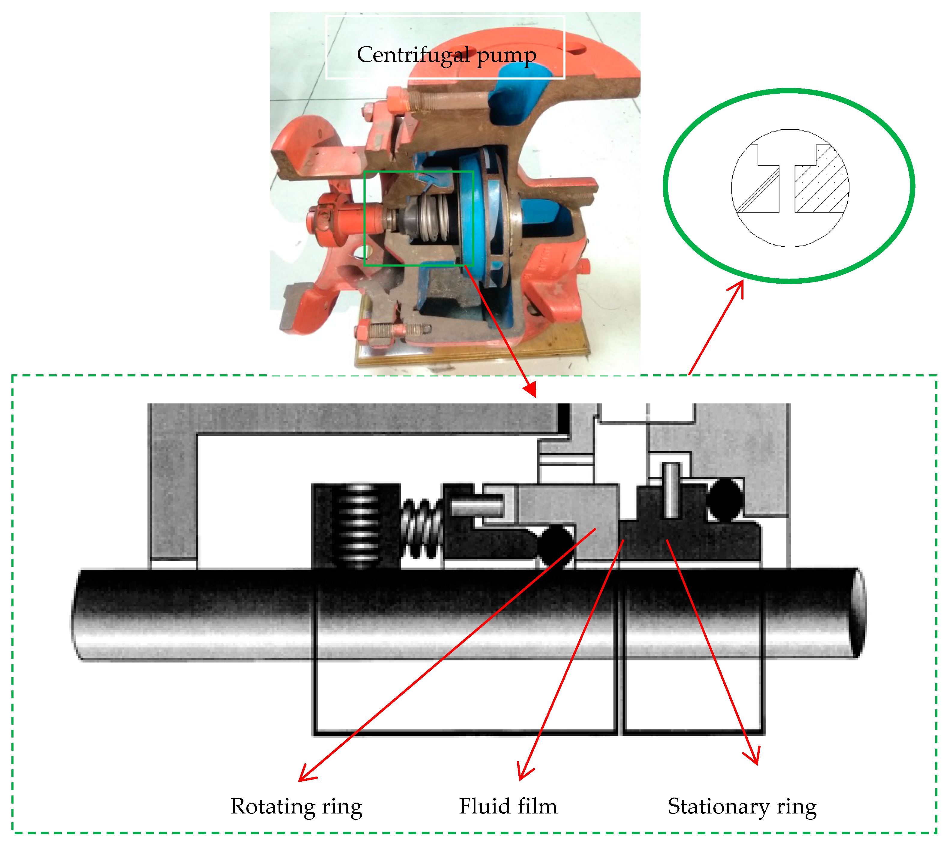
The geometry of the investigated mechanical seal in the RCP is shown in Figure 1. It consists of two sliding rings, namely the rotating ring and stationary ring. The inside and outside radius of the seal face are set as Ri = 140.25 mm and Ro = 151.25 mm, respectively. The rotating slide ring rotates counterclockwise at an angular speed of w. Between the rotating and stationary slide rings, the sealed medium (deionizer water is used in this case) flows from the outside zone to the inside chamber via the main leakage path with thickness hi.
The end face of the rotating slide ring is flat, and its roughness is less than 1 μm. The end face of the stationary slide ring consists of 9 wavinesses and a flat plane, as shown in Figure 2. The film thickness between the frictional pair is described as in Eq. 1 (Liu et al., 2011):
where hi, β, r, and θ stand for the thickness of the inner radius, radial angle on the stator face, and the coordinate of radial and rotating directions, respectively. Moreover, Ri, Rd, and Ro are the inner radius, dam radius, and outer radius, respectively. The dimensionless parameter α is defined as shown in Eq. 2:
The coupled thermal-hydraulic behavior within the mechanical seal is analyzed using the numerical technique, which starts from the establishment of the governing equations. To simplify the numerical simulation, some basic and reasonable assumptions are applied as follows:
Due to the very narrow seal gap, the large frictional heat will be produced by viscosity shear force in the process of operation, which will increase the temperature of the fluid film. Therefore, to simulate the temperature field, the energy equation including the dissipation item should be considered as in Eq. 5 (Shen et al., 2019):
In this equation, μ is the dynamic viscosity while u, v, and w are the components of fluid velocity u along with the directions of x, y, and z coordinates. When considering the viscosity-temperature effect, the viscosity is strictly dependent on the temperature distribution of the fluid film as shown in Eq. 7:
The fluid region (blur region) is the area enclosed by the inner and outer boundaries (r = Ri, and r = Ro) and the upper and lower sealing surfaces, as shown in Figure 1. To simulate the behavior of the proposed seal numerically, the boundary conditions should be determined.
The schematic of the boundary conditions is shown in Figure 3. For simplification, one of the waviness widths in the circumferential direction is taken, and the periodic cyclic boundaries are applied to the circumferential boundaries, i.e., the front and back boundaries. The considered mechanical seal is an external pressure structure. During the normal operation, the working fluid flows from the external high-pressure side to the internal low-pressure side, i.e., the outer boundary (r = Ro) is the inlet pressure boundary with po = 5 MPa, and the inner boundary (r = Ri) is the outlet pressure boundary with pi = 0 MPa. Since there is no slip between the boundary fluid and the sealing surface of the stationary slide ring, the no-slip boundary condition is applied to up and bottom boundaries (i.e., the upper and lower seal surfaces). The rotating speed of the sealing surface of the rotating slide ring is n = 1,500 rpm. The temperature boundary is applied to the inlet boundary, in which the inlet temperature is set as Tin = 323.15 K. The zero-gradient boundary of heat transfer is applied to the outlet, up, and bottom boundaries. The tolerance of all the simulations is set as 10−6.
To study the characteristics of the waviness end-face mechanical seal in reactor coolant pumps with the viscosity-temperature effect, some typical and concerned parameters are analyzed, including the leakage rate Q, the opening force Fopen and the liquid film stiffness kz. The leakage rate is one of the main parameters to ensure the safe and stable operation, which is defined as:
The appropriate leakage rate is important to ensure stable and safe operation. On the one hand, too low leakage may lead to the direct wear of seal ring end face, and on the other hand, the excessive leakage may cause seal failure.
Similarly, another important parameter, namely sealing opening force that characterizes the bearing capacity of the liquid film can be obtained by integrating the liquid film pressure along the sealing end face as:
This section analyzes the influences of the structural parameters on sealing performance considering the viscosity-temperature effect. The effects of thermo-hydrodynamic lubrication (THD) and hydrodynamic lubrication (HD) are compared and analyzed, and the optimal design parameters of the waviness mechanical seal are obtained.
Due to the small sealing clearance, when the sealing ring rotates at high speed, the viscous shear friction heat will be generated, which reduces the viscosity and correspondingly, reduces the leakage. Figure 4 shows the effects of the structural parameters of the waviness end-face mechanical seal on the leakage rate when considering the viscosity-temperature effect. The effect of film thickness on the leakage is shown in Figure 4A, in which the relative rate of change is the relative deviations of the HD solutions from the THD solutions. In general, as the film thickness increases, the leakage rates obtained from the THD and HD processes gradually close to each other, since that, as the film thickness increases, the viscous shear friction heat effect decreases correspondingly. When the film thickness is small enough, the HD process will strongly overestimate the leakage rate, while when the film thickness reaching 10 μm, the HD solution is much closed to the THD solution and the relative change rate decreases to 1.75%. These conditions indicate that the viscosity-temperature effect will be obvious when the liquid film is thin and will decrease as the thickness of the liquid film increases. Therefore, from this point of view, the film thickness should be large enough to ensure small viscosity-temperature. However, if the base film is too thick, the leakage will increase and the sealing effect will not be achieved. Therefore, the base film thickness of the seal design should be kept within the appropriate range.
Figure 4B shows the effect of the taper of the stationary slide ring end-face on the leakage. Similar to that of the base film thickness, as the taper increases, the viscosity-temperature effect on the leakage rate decreases. As the taper increases, the film thickness of the taper zone in the seal clearance increases, and the viscous shear friction heat decreases correspondingly. Considering the viscosity-temperature effect, the relative change rate of the leakage decreases from the maximum of 99.49–50.47% with the increase of the taper, which indicates that the taper should be large enough to reduce the viscosity-temperature effect.
Figure 4D shows the effect of the dimensionless parameter α on the leakage rate, i.e., the effect of waviness amplitude of stationary slide ring end-face on the leakage rate. The increase of α means the increase of the waviness amplitude, which will reduce the film thickness of the waviness region, and increase the viscous shear friction heat. Therefore, with α increasing, the effect of viscosity-temperature on the leakage increases correspondingly. On the other hand, the decrease in film thickness is still limited due to the increase of waviness amplitude. Therefore, from the point of the relative change rate variation, it does not change much, which varies between 40.02 and 50.17%. However, from the point of the relative change rate value, the viscosity-temperature effect is still large. Figure 4E shows the effect of the wave number on the leakage rate. In general, the variation of wavenumber has little effect on the relative change rate of leakage. The relative change rate of leakage remains between 67.66 and 72.1%.
This part analyzes the influence of the viscosity-temperature effect on the opening force. As the temperature increase, the fluid viscosity will decrease and the viscosity-temperature effect for the waviness end-face mechanical seal will be reduced correspondingly. Meanwhile, the hydrodynamic effect and the hydrostatic effect will be reduced. Therefore, the opening force considering the viscosity-temperature effect (THD solutions) will be less than that without considering the viscosity-temperature effect (HD solutions). Figure 5 shows the effects of different structural parameters on the opening force, the solutions with and without considering the viscosity-temperature effect are compared with each other. Different from the leakage, the relative change rate is always less than 0, i.e., the opening force with considering the viscosity-temperature effect is lower than that without considering the viscosity-temperature effect.
Figure 5B shows the effect of the taper of stationary slide ring end-face on the opening force, in which the opening force increases as the taper increases and the relative change rate decreases as the taper increases. As the taper increases, the film thickness in the waviness region increases and the viscous shear friction heat decreases. Therefore, the effect on the viscosity of the sealing medium reduces. The effect on the opening force and the relative change rate of the opening force will decrease with the increase of taper, which varies from −1.26 to −17.38%.
Figure 5C shows the effect of the dam width ratio on the opening force, in which the opening force decrease as the dam width ratio increases, while the relative change rate increases as the dam width ratio increases. With the increase of the dam width ratio, the dam area increases, the viscous shear friction heat increases, and the influence on the viscosity of the sealing medium increase correspondingly. The increase of the dam width ratio increases the influence of opening force, and the relative change rate of opening force increases from −0.72 to −17.41%.
Figure 5D shows the effect of α on the opening force, in which the opening force decreases as α increases, and the relative change increases first and then decreases. As α increases, the waviness amplitude increases, and the viscous shear friction heat increases, thus the viscosity change increase also. Therefore, with the increase of α, the influence of viscosity-temperature on the opening force increases. When α increases to a certain value, the hydrodynamic effect of the waviness end-face seal becomes strong enough, leading to a decrease in the relative change rate of opening force, from −1.26 to −1.88%.
Figure 5E shows the effect of the wave number on the stationary slide ring end-face on the opening force. The opening force increases as the wave number increases and the viscosity-temperature effect makes the opening force lower. The increase of wave number will make the high-temperature region denser, thus weakening the hydrostatic effect, and the opening force will be relatively small. However, the hydrodynamic effect will be enhanced as the wavenumber increases. The relative change rate of the opening force is not large, which varies between 5.56 and 6.65%.
This part studies the influence of structural parameters of the mechanical end-face seal on the fluid film stiffness with considering the viscosity-temperature effect. The film stiffness under different structural parameters is shown in Figure 6, with and without considering the viscosity-temperature effect, respectively. To analyze the effect of the viscosity-temperature effect on the fluid film stiffness, the relative change rate of the liquid film stiffness was calculated. The negative sign of the relative change rate indicates the decrease of film stiffness.
Figure 6B illustrates the effect of the taper of stationary slide ring on the liquid film stiffness, in which both the film stiffness and the relative change rate increase first and then tend to stable. When considering the viscosity-temperature effect, the liquid film stiffness tends to be lower than that of the HD solutions. This effect will be decreased as the taper increases. As the taper degree decreases, the viscosity-temperature effect generates a more striking impact on the liquid film stiffness, and the liquid film stiffness can be negative, i.e., the opening force increases as h increases. This phenomenon is caused by the generated viscous shear friction heat, which could be very unfavorable for the stable operation of the seal if the taper angle is extremely small. Under the optimal circumstance with the largest taper degree, the relative rate of change can be as low as 44.67%, which could be much better for the stable operation. In consideration of this, credence should be given to a relatively larger taper degree when designing the mechanical seal.
Figure 6C depicts the effect of the dam width ratio on the fluid film stiffness. When the dam width ratio being equal to zero, there is no dam area and the viscosity-temperature effect will increase the liquid film stiffness. However, when the dam area exists, the viscosity-temperature effect, in turn, decreases the film stiffness. As the dam area increases, an increasing amount of viscous shear friction heat is generated, which leads to a non-negligible viscosity-temperature effect on the liquid film stiffness. According to Figure 6C, when the dam width ratio is large enough, the film stiffness without considering the viscosity-temperature effect is close to 0 and the film stiffness with considering the viscosity-temperature has a relative larger negative value. The relative change rate of the liquid film stiffness can reach a very large value, which will threaten the operation of the seal. As the dam width shrinks, the relative change rate of the liquid film stiffness can decline to 2.27%. The above result indicates the importance of the small dam width ratio in the design of the mechanical seal.
According to these analyses, the viscosity-temperature effect should be taken into consideration in analyzing the performance of the waviness end-face mechanical seal. The neglect of the viscosity-temperature effect will lead to the overestimation of the film stiffness, which will destroy the safe and stable operation of the seal. Besides, to control the leakage while ensuring the sufficient bearing capacity and stable operation, it is necessary to set appropriate structural parameters of the waviness end-face mechanical seal in the design. In this case, the mechanical seal with the base film thickness being kept at 2.5 μm, the taper being around 900 μrad, the dam width ratio being around 0.2, α being around 0.8, and the wave number being 9 can be one of the optimal combinations for the best performance.
In the final part, the influence of the structural parameters of the waviness end-face mechanical seal on the temperature field of the liquid film is studied. When considering the viscosity-temperature effect, the viscosity of the working fluid decreases as the temperature increases. This property will reduce the generated viscous shear friction heat and suppresses the increase of temperature in turn. According to these characteristics, it can be predicted that the maximum temperature difference in the fluid film with considering the viscosity-temperature effect will be smaller than that without considering the viscosity-temperature effect.
Figure 7D depicts the effect of α on the maximum temperature difference in the liquid film at two stages. Under different α, the maximum temperature difference increases in different trends. When α < 0.6, the maximum temperature increases slowly, and after that, the temperature difference increases sharply. This condition is caused by the increase of α when α is big enough. At large α, the increase in α will cause a high temperature in the wave area of the outer diameter side, which results in a sharp increase in temperature difference. For the safe operation, this sharp increase should be avoided in designing the WTD mechanical seal, which requires that the value of α should be set no more than 0.8. The relative change rate between the THD and HD solutions slightly lowered, and always kept between 0.2–0.5%, indicating that the viscosity-temperature effect has a non-obvious influence under this condition.
Figure 7E shows the effect of the wavenumber of the mechanical seal on the maximum temperature difference in the liquid film. In general, as the wave number increase, the maximum temperature decreases with different trends. It can be found that around k = 9–15, the temperature difference has a plateau period, and then decreases slowly. Therefore, to ensure the relatively small temperature difference and reduce the mechanical difficulty, the wave number can be set as 9. The variation of the relative change rate ranges merely from 0.5 to 0.6%, which is relatively stable.
In short, the consideration of the viscosity-temperature effect in the liquid film of the sealing gap is important in controlling the temperature rise. It is presented in Figure 7 that, when the base film thickness is greater than 2.5 μm, the taper is greater than 600 μrad, the dam width ratio is less than 0.2, and α is at around 0.8, the viscosity-temperature effect on the temperature rise could be acceptable. Under such circumstances, the mechanical seal is expected to have a better performance.
The mechanical seal is one of the main components of the reactor coolant pump (RCP) in the nuclear power plant, whose performance strongly influences the safety and stability of nuclear reactor operation. This work studies the characteristics of the waviness end-face mechanical seal, where, considering both the viscosity dissipation and viscosity-temperature effects, the influence of heat transfer and fluid flow characteristics is revealed. The sealing medium flow is guided by Navier-Stokes and Energy balance equations, the simulations of which are performed using an open-source software OpenFOAM under different conditions. Since the effect of viscous shearing for the utilized fluid medium can result in a huge amount of heat waste in the seal ring, which may end up threatening the seal’s normal operations. This study also investigated the liquid film’s thermal evolution characteristics. Note also that, in line with the working fluid properties, thermal influence analysis requires the consideration of the liquid film’s viscosity characteristics. Concluding remarks on the present study can be summarized as follows:
1) The viscosity-temperature effect can increase the leakage, while this effect decreases the opening force and the liquid film stiffness. In particular, when considering the viscosity-temperature effect, the values of liquid film stiffness may have a negative value. These properties will lead to a higher risk in the safe and stable operation of the mechanical seal. According to these analyses, it can be concluded that the viscosity-temperature effect plays a negative role in the mechanical seal performance, which cannot be ignored in the design of the mechanical seal.
2) From the perspective of liquid film temperature rise, the viscosity-temperature effect can reduce the temperature rise in the liquid film, which improves its safe operations. Based on the above considerations, when designing the waviness mechanical seal, the optimal structural parameters can be set as hi = 2.5μm, β = 900μrad (Rd-Ri)/(Ro-Ri) = 0.2, α = 0.8, and k = 9.
More research endavours are still needed to extend the present study to farther operating conditions where for instance the sealing medium (utilized working fluid in the seal gap) would be changed to other commonly utilized fluids in these system to investigate the associated impact of the sealing performance. Moreover, it will be more informative to explore the eventual changes in flow field characteristics such the pressure and temperature contours using the CFD post-processing component.
All claims expressed in this article are solely those of the authors and do not necessarily represent those of their affiliated organizations, or those of the publisher, the editors and the reviewers. Any product that may be evaluated in this article, or claim that may be made by its manufacturer, is not guaranteed or endorsed by the publisher.
Clark, R., Azibert, H., and Oshinowo, L. (2002). Computer Simulation of Mechanical Seal Leads to Design Change that Improves Coolant Circulation. Mater. Des. 23, 113–117. doi:10.1016/s0261-3069(01)00048-6
Danos, J. C., Tournerie, B., and Frêne, J. (2000). Notched Rotor Face Effects on Thermohydrodynamic Lubrication in Mechanical Face Seal. Tribology 38, 251–259. doi:10.1016/s0167-8922(00)80130-3
Djamaï, A., Brunetière, N., and Tournerie, B. (2010). Numerical Modeling of Thermohydrodynamic Mechanical Face Seals. Tribology Trans. 53, 414–425. doi:10.1080/10402000903350612
Falaleev, S. V. (2015). Techniques for Calculating the Hydrodynamic Characteristics of Mechanical Face Seals with Gaps of Complex Forms. J. Friction Wear. 36(2):177–183. doi:10.3103/S1068366615020063
Feng, X. D., Dazhuan, W. U., Yang, L. F., and Jia, Y. (2016). Technology for CNP1000 Shaft Sealed Reactor Coolant Pump. J. Drainage Irrigation Machinery Eng. 34 (7):553–560. doi:10.3969/j.issn.1674-8530.15.0162
Harp, S. R., and Salant, R. F. (1998). Analysis of Mechanical Seal Behavior During Transient Operation. J. Tribology 120, 191–197. doi:10.1115/1.2834409
Liu, W., Liu, Y., Wang, Y., and Peng, X. (2011). Parametric Study on a Wavy-Tilt-Dam Mechanical Face Seal in Reactor Coolant Pumps. Tribology Trans. 54, 878–886. doi:10.1080/10402004.2011.611325
Liu, Y., Liu, W., Li, Y., Liu, X., and Wang, Y. (2015). Mechanism of a Wavy-Tilt-Dam Mechanical Seal under Different Working Conditions. Tribology Int. 90, 43–54. doi:10.1016/j.triboint.2015.03.020
Merati, P., Okita, N. A., Phillips, R. L., and Jacobs, L. E. (1999). Experimental and Computational Investigation of Flow and Thermal Behavior of a Mechanical Seal. Tribology Trans. 42, 731–738. doi:10.1080/10402009908982276
Nilsson, J., Wojciechowski, A., Stromberg, A. B., Patriksson, M., and Bertling, L. (2009). An Opportunistic Maintenance Optimization Model for Shaft Seals in Feed-Water Pump Systems in Nuclear Power Plants. IEEE Bucharest, Powertech, 1–8. doi:10.1109/ptc.2009.5281892
Pascovici, M. D., and Etsion, I. (1992). A Thermo-Hydrodynamic Analysis of a Mechanical Face Seal. Stle Tribology Trans. 114, 639–645. doi:10.1115/1.2920930
Peng, X. D., Liu, X., Meng, X. K., Sheng, S. E., and Li, J. Y. (2012). Thermo-elasto-hydrostatic Effect Analysis of a Double Tapered Hydrostatic Mechanical Seal in Reactor Coolant Pumps. Tribology 32, 244–250. doi:10.1109/APPEEC.2012.6306984
Salant, R. F., Payne, J. W., Johnson, W. R., and Boles, G. (2018). Simulation of a Hydraulically Controllable Reactor Coolant Pump Seal. Tribology Int. 122, 163–168. doi:10.1016/j.triboint.2018.02.024
Shen, S., Qian, Z., and Ji, B. (2019). Numerical Analysis of Mechanical Energy Dissipation for an Axial-Flow Pump Based on Entropy Generation Theory. Energies 12, 4162. doi:10.3390/en12214162
Simon, A. (2018). Robust, Gas-Lubricated Mechanical Seal for Processing Natural Gas. Sealing Technology. 2018 (5), 5–6. doi:10.1016/S1350-4789(18)30206-X
Stanghan‐Batch, B., and Iny, E. H. (1973). A Hydrodynamic Theory of Radial‐face Mechanical Seals. J. Mech. Eng. Sci. 15, 17–24. doi:10.1243/JMESJOUR197301500502
Tournerie, B., Danos, J. C., and Frêne, J. (2001). Three-Dimensional Modeling of THD Lubrication in Face Seals. J. Tribology 123, 196–204. doi:10.1115/1.1327584
Wen, Q. F., Ying, L., Huang, W. F., Suo, S. F., and Wang, Y. M. (2013). The Effect of Surface Roughness on thermal-elasto-hydrodynamic Model of Contact Mechanical Seals. Sci. China(Physics,Mechanics Astronomy), 56, 112–121. doi:10.1007/s11433-013-5266-3
Young, L. A., Key, B., Philipps, R., and Svendsen, S. (2003). Mechanical Seals with Laser Machined Wavy SiC Faces for High Duty Boiler Circulation and Feedwater Applications. Lubrication Eng. 59, 30–39.
The scope of our mechanical seal product range far exceeds any other seal manufacturer. From small elastomer bellows seals used in millions of domestic water pumps to double mechanical seals that ensure maximum sealing safety and large, highly customized dry-running gas seals for mission critical high speed turbo compressors, John Crane has the right product for any application.
Our world-class rotating equipment technologies, paired with an unmatched breadth of applied engineering expertise, meet virtually all international standards including API 682 and help plants reduce maintenance costs, slash down time and improve reliability. When it comes to keeping your rotational equipment running 24/7, John Crane’s comprehensive range of mechanical seals and systems has you covered.
A range of seals for mission-critical applications, designed to solve the application-specific challenges of each industry. From API 682 compliance for the oil and gas industries, using gas seal technology on our innovative pump gas seals to eliminate fugitive emissions, dealing with slurry in the mining and minerals processing industries, to the difficulties associated with maintenance on large pumps and rotating equipment — we have a solution.
Dry-running, non-contacting gas seals have been the industry standard since the early 1980s for turbomachinery. John Crane gas seals, separation seals and support, monitoring, control and conditioning systems — the heart of any reliable sealing solution — are constantly evolving to meet the needs of customers. The product portfolio is supported by unrivaled global service capability providing repair, retrofit, gas seal storage and reliability expertise, delivering total solutions throughout the product lifecycle.
In industries like chemical, pharmaceutical, pulp and paper, and food and beverage, safeguarding and compliance with industry standards, avoiding contamination and efficiency are always top priorities. Our range of vessel and agitator seals optimize equipment performance, maintain product purity and conform to industry regulations, no matter where you are.
Our range of mechanical seals, packing and bearing isolators combines advanced, thoroughly proven technologies with extensive industry expertise to create a range of products characterized by innovative design concepts and outstanding manufacturing quality. Tried, tested and effective solutions for virtually any application that deliver robust performance, reduced installation times and lower maintenance costs.
Create the optimum operating environment that will ensure outstanding seal performance and reliability. Our comprehensive range of engineered pressure reservoirs, gas seal control panels, heat exchangers and abrasive separators can be combined to produce the perfect seal support system for any application.
Designed to overcome rigorous challenges, our comprehensive suite of seal face technologies combat limited seal face lubrication that adversely affects reliability, cost and durability. Our engineers designed these face treatments to extend rotating equipment life through advanced micro machined patterns and features improving seal face lubrication that optimizes equipment performance. We deliver the right face technology for the right application.
A single mechanical seal is a type of mechanical seal which consists of one primary seal and it seals from process to atmosphere.There is always some leakage either to atmosphere or into process depending on the process pressure.
-Found as Wet-running (liquid phase between sealing faces) on liquid pumps, Dry-running (gaseous phase between sealing faces) on blowers/compressors/mixers.
-Nearly always dry running contacting seal (mechanical seal face wear) for top mounted mixers. For side and bottom mounted (seal is submerged) a wet-running seal is normally specified.
If you have any query around how to install a single mechanical seal for agitators or mixers or have some concerns around the seal failures, why not contact one of our mechanical seal specialists below to discuss it in more detail and find out how we can help solve your issues and get your process back up and running reliably again.

A double mechanical seal is a type of mechanical seal withtwo primary seals or sets of faces, it can operate in various arrangements with a) a barrier (containment) between the sets of faces or b) a buffer (mixing).
2. A Double Mechanical Seal (Barrier) – Wet => is a double seal where the barrier fluid is a liquid. It is generally the most robust seal. It has a good pressure, speed and temperature capabilities.
If you have any query around how to install double mechanical seals for agitators or mixers or have some concerns around the seal failures, why not contact one of our mechanical seal specialists below to discuss it in more detail and find out how we can help solve your issues and get your process back up and running reliably again.

... a dual pressurized gas barrier metal bellows seal utilizing APGS non-contacting seal face technology. Welded metal bellows eliminate dynamic O-ring hang-up in a compact ...
• Drive mechanisms external to the product;• Seal faces positioned for maximum protection;• A dynamic elastomer moves on a non-metallic surface, eliminating fretting defects;• Hydraulically balanced;• Cartridge easy to ...
• Static grafoil gaskets;• Temperatures up to 425 ºC;• Inconel bellows available;• Cartridge easy to install;• Metal bellows provide better faces alignment;• Does not have dynamic gaskets;• Self-cleaning;• Adapts to API ...
The product is constructed with the combination of materials such as graphite, silicon carbide, tungsten carbide and aluminum oxide. Then, a secondary sealing of materials are acrylonitrile rubber, fluorine and silicon ...
... carbide, tungsten carbide and Aluminum oxide, with the secondary sealing. The secondary sealings consist of Acrylonitrile rubber, Fluorine rubber, Ethylene propylene rubber, PTFE, metal component and ...
This seal withstands -45℃-200℃ temperature, over 2.0Mpa pressure, in 15m/s speed or over. The series V1,Q1,Q2,U2,U1 are stationary, A,B,Q1,Q2,U2 are rotary and V,P and E are secondary seal. It has a standard ...
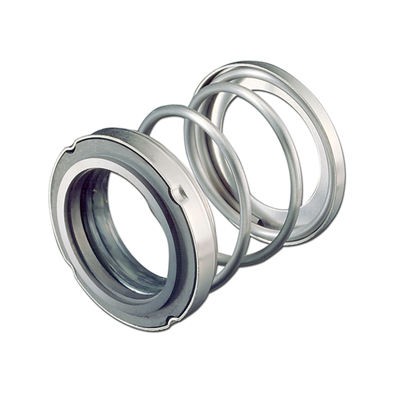
The MTM10-11 is a conical spring mechanical seal developed by Microtem. It is mainly used for general services machinery at low and medium pressure. This unbalanced mechanical seal ...
... manufactured by MICROTEM, is a conical spring mechanical seal that can compensate positioning errors and withstand stresses created by vibrations. The contact surface can be made with silicon carbide, ...
Single mechanical seal, balanced, independent of the direction of rotation with multi-spring configuration. The MTM180 Series represents the mechanical seal with the ...
Aura™ reduces operational and transactional costs using a patented polymeric sealing device. Aura reduces leakage rates by up to 15 percent, lowering the total cost of operation while protecting the environment. An enhanced rotor design ...
The AESSEAL® API Type A, B and C single-seal range offers the user an unprecedented range of API engineered sealing solutions to suit all application ...
Cartridge Seals by CinchSeal are customized mechanical seals for rotary air locks in bulk handling equipment. They are designed to replace lip and packing seals in screw ...
Our Mechanical seal model CR is widely used for GRUNDFOS-PUMP . The normal material combination include SIC/SIC/viton/machined ss304,TC/TC/VITON/machined ss304 and SIC/ SIC/VITON/SS304. ...
Clark Seals Ltd. was contacted by the largest manufacturer of commercial laundry equipment with a problem they were having with seals leaking in sandy environments. Sand was getting between the sealing surfaces of the mechanical seal, grooving the face and causing leakage.
To solve the problem, we designed a custom two-piece integrated sealing solution that sealed against the top and bottom of the tub. The top seal was designed to press-fit around the tub bearing to improve alignment between the transmission, tub and agitator and a triple sealing lip to prevent water, sand and debris from entering the bearing cavity. The bottom seal was designed with a locking pin to resist torque and press-fit into the top seal during installation. To further reduce sand and other contaminants, our engineers developed and patented a unique negative "R"; sealing lip geometry that allowed the sprung lip to perform as an excluder lip and keep all sand out of the sealing environment.
The end result was a patented sealing solution that eliminated warranty claims, cost 80% less and lasted more than 700% longer than the mechanical seal it replaced.

Mechanical seals are utilized when sealing between a rotating shaft and a vessel, such as a pump housing. They are made to keep liquids from entering or exiting a container while enabling the shank to move, allowing machinery to run smoothly and without interruption. The application, installation, and operation must be considered to ensure reliability when choosing a mechanical seal.
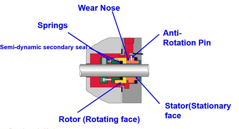
A mechanical seal consists of two flat faces, one rotating and one stationary, mounted perpendicular to the shaft. The rotation of the rotary seal ring against the stationary seal ring causes a rapid pressure drop across the primary seal interface caused by friction on the liquid molecules between the seal faces. Liquid molecules also act as miniature ball bearings to lubricate and reduce friction, reducing heat and wear.
Cartridge, component, and air are the three most widely utilized types of mechanical seals. The types differ in their design, structure, and distribution of the hydraulic forces on their faces.
A cartridge-mounted, end-face mechanical seal is a self-contained mechanism with sealing components, including a gland, sleeve, and hardware. A cartridge seal enables the manufacturer to preassemble and calibrate the unit. Installation and maintenance are simplified because the manufacturer handles these tasks. Cartridges may be supplied with either one or two seals, depending on the application’s needs.
Component mechanical end-face seals consist of a rotating part and a stationary seal that mount to a gland or housing. Since they are not preset, maintenance and installation are more involved than cartridge seals, and installing them requires skilled professionals who can configure them effectively.
Pneumatic, non-contacting air seals are used to seal rotating shafts. These seals are often used when dry powder or slurry is present. Product loss, emissions, and contamination are avoided by using small amounts of air or inert gas, and this air is restricted to provide positive pressure and an efficient seal.
Stationary primary face.This part is attached to the stationary housing of the pump, mixer, or other apparatus where the rotating shaft travels and is sealed against the moving primary sealing component.
Mechanical loading devices.This mechanism presses primary sealing parts together and closes them. Single, multiple, wave or metal bellows can be used.
Static or dynamic secondary seals.These seals are used when there is motion between surfaces, serving as mechanical protection that adjusts on shaft movement that could harm the seal faces.
Mechanical seals are preferred for most industrial applications, especially by pump manufacturers, as mechanical seals reduce fluid leaks better than other approaches. Among its many benefits includes:
Efficient leakage prevention. Mechanical seals are perfect for procedures involving chemicals such as hydrochloric acid, sulfuric acid, and other hazardous substances.
Component durability. Sleeves and shafts do not wear out quickly. Mechanical seals reduce preventive maintenance if well-installed and can ensure durable seals.
Mercer Gasket & Shim offers a variety of high-performance mechanical seals that provide superior sealing capabilities in even the most demanding environments and conditions. Our practical and durable mechanical seals help reduce operational costs and improve production and system reliability.
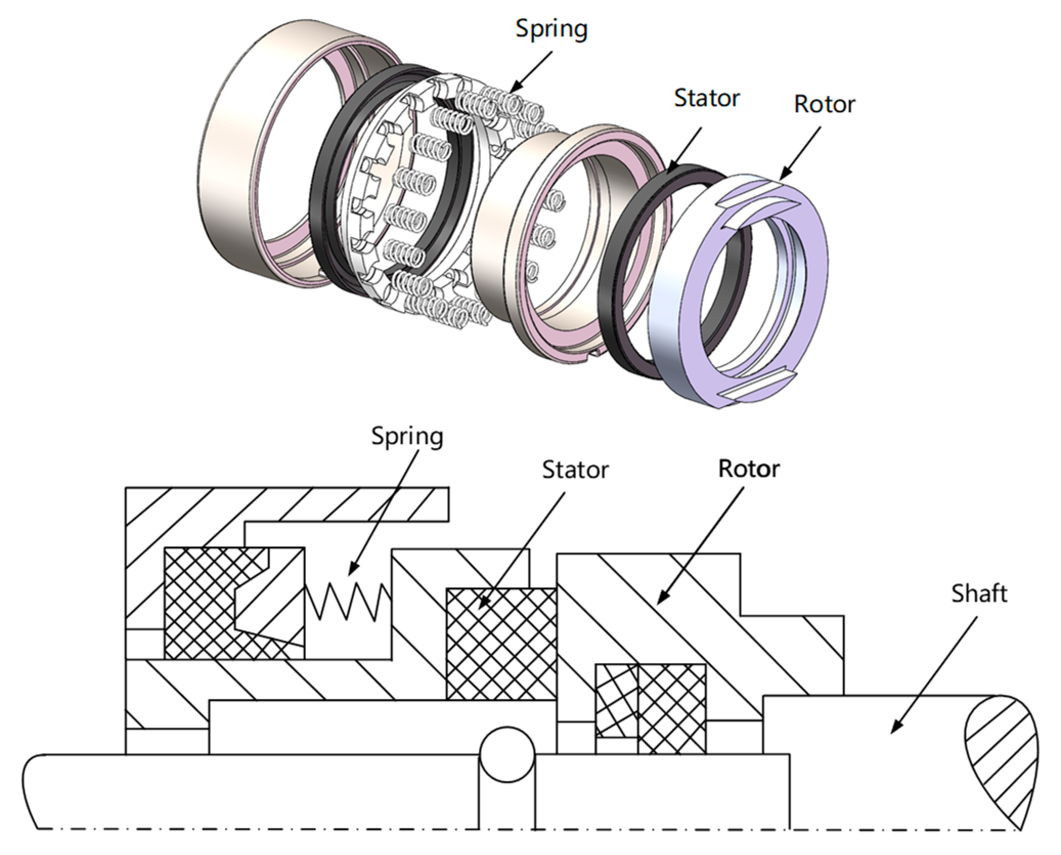
Elements d1 and a1 bear and slide on each other, creating a seal at their interface. One group of parts is connected to the rotating shaft and the other to the machine"s case. The spring keeps the elements tight against each other, maintaining the seal and allowing for wear.
An end-face mechanical seal, or a mechanical end-face seal, also referred to as a mechanical face seal but usually simply as a mechanical seal, is a type of seal used in rotating equipment, such as pumps, mixers, blowers, and compressors. When a pump operates, the liquid could leak out of the pump between the rotating shaft and the stationary pump casing. Since the shaft rotates, preventing this leakage can be difficult. Earlier pump models used mechanical packing (otherwise known as gland packing) to seal the shaft. Since World War II, mechanical seals have replaced packing in many applications.
An end-face mechanical seal uses both rigid and flexible elements that maintain contact at a sealing interface and slide on each other, allowing a rotating element to pass through a sealed case. The elements are both hydraulically and mechanically loaded with a spring or other device to maintain contact. For similar designs using flexible elements, see radial shaft seal (or "lip seal") and O-ring.
An end-face mechanical seal consists of rotating and stationary components which are tightly pressed together using both mechanical and hydraulic forces. Even though these components are tightly pressed together, a small amount of leakage occurs through a clearance that is related to the surface roughness.
The seal ring and mating ring are sometimes referred to as the primary sealing surfaces. The primary sealing surfaces are the heart of the end-face mechanical seal. A common material combination for the primary sealing surfaces is a hard material, such as silicon carbide, ceramic or tungsten carbide and a softer material, such as carbon. Many other materials can be used depending on pressure, temperature and the chemical properties of the liquid being sealed. The seal ring and mating ring are in intimate contact, one ring rotates with the shaft and the other ring is stationary. Either ring may be rotating or stationary. Also, either ring may be made of hard or soft material. These two rings are machined using a process called lapping in order to obtain the necessary degree of surface finish and flatness. The seal ring is flexible in the axial direction; the mating ring is not flexible.
By definition, the seal ring is the axially flexible member of the end-face mechanical seal. The design of the seal ring must allow for minimizing distortion and maximizing heat transfer while considering the secondary sealing element, drive mechanism, spring and ease of assembly. Many seal rings contain the seal face diameters, although this is not a requirement of the primary ring. The seal ring always contains the balance diameter.
The shape of the seal ring may vary considerably according to the incorporation of various design features. In fact, the shape of the seal ring is often the most distinct identifying characteristic of a seal.
By definition, the mating ring is the non-flexible member of the mechanical seal. The design of the mating ring must allow for minimizing distortion and maximizing heat transfer while considering ease of assembly and the static secondary sealing element. The mating ring can contain the seal face diameters, although this is not a requirement of the mating ring. To minimize primary ring motion, the mating ring must be mounted solidly and should form a perpendicular plane for the primary ring to run against. Like seal rings, mating rings are available in many different shapes.
Secondary sealing elements are gaskets which provide sealing between the seal ring and shaft (or housing) and the mating ring and shaft (or housing). Typical secondary sealing elements include O-rings, wedges or rubber diaphragms. The secondary sealing elements (there may be a number of them) are not rotating relative to one another. The secondary sealing element for the mating ring is always static axially (although it may be rotating). Secondary sealing elements for the seal ring are described as being either pusher or non-pusher in the axial direction. The term pusher is applied to secondary seals that must be pushed back and forth by the movement of the shaft or primary ring whereas non-pusher secondary seals are static and associated with bellows seal rings.
In order to keep the primary sealing surfaces in intimate contact, an actuating force is required. This actuating force is provided by a spring. In conjunction with the spring, axial forces may also be provided by the pressure of the sealed fluid acting on the seal ring. Many different types of springs are used in mechanical seals: single spring, multiple springs, wave springs, and metal bellows.
The term "hardware" is used to describe various devices which hold the other components together in the desired relationship. For example, a retainer might be used to package the seal ring, secondary sealing element and springs into a single unit. Another example of hardware is the drive mechanism which is necessary to prevent axial and rotational slippage of the seal on the shaft.
There are a number of different ways in which “seals” may be classified. Sometimes a reference to a “seal” may be to a sealing system whereas other times the reference is to a device such as a gasket, an O-ring, compression packing, etc. In this article, the reference is to an end-face mechanical seal.
One such method of classification considers design features or the configuration in which these features may be used. Classification by Design accounts for the details and features incorporated into a single seal ring/mating ring pair. Classification by Configuration includes the orientation and combination of the seal ring/mating ring pair.
In general, design features are not completely independent; that is, emphasis of a particular feature may also influence other features. For example, selection of a particular secondary sealing element may influence the shape of the seal ring.
The most common seal face design is a plain, flat, smooth surface but there are many special treatments intended for specific applications. The most common objective for the face treatment is to reduce the magnitude of mechanical contact. In general, face treatments provide a means of modifying the pressure distribution between the seal faces through hydrostatic or hydrodynamic topography. Seal face topography refers to the three dimensional aspects of the seal face surface.
In addition to the spring force, the seal faces are pushed together through pressure acting hydrostatically on the geometry of the seal. The ratio of the geometric area tending to close the seal faces to the area tending to open the seal faces is called the balance ratio.
Pusher seals employ a dynamic secondary sealing element (typically an O-ring) which moves axially with the seal ring. Bellows seals employ a static secondary seal (such as an O-ring, high temperature graphite packing, or elastomeric bellows and axial movement is accommodated by contraction or expansion of the bellows.
In addition to retaining the other components, the seal hardware includes the drive mechanism which is necessary to prevent axial and rotational slippage of the seal on the shaft. The drive mechanism must withstand the torque produced by the seal faces while also allowing the seal ring to move axially. In addition to torque, the drive mechanism must withstand the axial thrust produced by hydrostatic pressure acting on the components. The various types of drive mechanisms include: dent drive, key drive, set screws, pins, slots, snap rings and many more. Typically, the retainer for the seal ring might include set screws, a dent or slot drive, recesses for the spring and a snap ring to complete the assembly. In contrast, mating ring hardware might be only a pin or slot to prevent rotation. Corrosion is a major consideration when selecting seal hardware.
Both the seal ring and mating must accommodate secondary sealing elements. In some designs, various retainers, sleeves and other components may also include secondary sealing elements. Whereas a simple O-ring might require only a groove for fitting, some secondary sealing elements (for example, packing) might require mechanical compression. Although O-rings are available in many elastomers, sometimes an elastomer might not be compatible with the fluid being sealed or might be considered too expensive. In such cases, a secondary sealing element might be manufactured from perfluoroelastomer and shaped in the form of a wedge, V or U.
Although all end-face mechanical seals must contain the five elements described above, those functional elements may be arranged or oriented in many different ways. Several dimensional and functional standards exist, such as API Standard 682 - Shaft Sealing Systems for Centrifugal and Rotary Pumps, which describes the configurations for used in Oil & Gas applications. Even though the scope of API 682 is somewhat limited, it may be extended to describe end-face mechanical seals in general.
Configuration refers to the number and orientation of the components in the end-face mechanical seal assembly. For example, springs may be rotating or stationary. Single or multiple pairs of sealing faces may be used. For multiple seals, the individual pairs of sealing faces may be similarly oriented or opposed. Containment devices such as bushings may or may not be used as part of the configuration.
The basic components of an end-face mechanical seal may be installed directly onto the shaft but a popular approach is to pre-assemble the components into some sort of package for ease of installation.
Either the seal ring or the mating ring may be the rotating element. Seals with rotating seal rings are said to be "rotating" seals; seals with stationary seal rings are said to be "stationary" seals. Because the springs are always associated with the seal rings, sometimes the distinction is made as "rotating springs" versus "stationary springs". For convenience, rotating seals are used in most equipment; however, stationary seals have some advantages over rotating seals. In small, mass-produced seals for modest services, the entire seal may be placed in a package which minimizes shaft and housing requirements for the equipment. Stationary seals are also used to advantage in large sizes or at high rotational speeds.
When classifying end-face mechanical seals by configuration, the first consideration is whether there is only one set of sealing faces or multiple sets. If multiple sets are used, are the sets configured to be unpressurized or pressurized.
A tandem seal consists of two sets primary sealing surfaces with the space in-between the two seals filled with a compatible low pressure fluid called the buffer fluid. This buffer fluid/space may be monitored to detect performance of the assembly. Unfortunately, the definition of “tandem seal” was often stated in a confusing manner. In particular, a tandem seal was usually described as two seals pointing in the same direction; that is, in a face-to-back orientation. This orientation is not necessary to the function of the configuration and the API chose to use the term Arrangement 2 instead of tandem in the API 682 standard.
A double seal consists of two sets primary sealing surfaces with the space in-between the two seals filled with a compatible pressurized fluid called the barrier fluid. This barrier fluid/space may be monitored to detect performance of the assembly. Unfortunately, the definition of “double seal” was often stated in a confusing manner. In particular, a double seal was usually described as two seals pointing in the opposite direction; that is, in a back-to-back orientation. This orientation is not necessary to the function of the configuration and the API chose to use the term Arrangement 3 instead of double in the API 682 standard.
An end-face mechanical seal generates heat from rubbing and viscous shear and must be cooled to assure good performance and reliable operation. Typically, cooling is provided by circulating fluid around the seal. This fluid, known as a flush, may be the same as the fluid being sealed or an entirely different fluid. The flush may be heated, filtered or otherwise treated to improve the operating environment around the seal. Collectively, the flush and treating systems are known as piping plans. Piping plans for mechanical seals are defined by American Petroleum Institute specification 682 and are given a number. Some piping plans are used for single seals and some only for multiple seals. Some piping plans are intended to provide a means of monitoring the seal. Some sealing systems include more than one piping plan. See the table below for a summary and description of piping plans.
The first commercially successful mechanical seal to be used on centrifugal pumps was probably made by the Cameron Division of the Ingersoll-Rand Company. The Cameron seal was installed in a number of centrifugal pipeline pumps in 1928.
Mechanical seals in the 1930s often used a face combination of hardened steel versus leaded bronze. Carbon-graphite was not widely used as a seal face material until after World War II. Soft packing was used as secondary sealing elements. The O-ring was developed in the 1930s but not used in mechanical seals until after World War II.
In the late 1930s, probably about 1938 or 1939, mechanical seals began to replace packing on automobile water pumps. The famous Jeep of WWII used a rubber bellows seal in the water pump. After WWII, all automobile water pumps used mechanical seals.
In the mid-1940s pump manufacturers such as Ingersoll-Rand, Worthington, Pacific, Byron Jackson, United, Union and others began to make their own mechanical seals. Eventually most of these companies got out of the seal business but the Byron Jackson seal became the Borg-Warner seal (now Flowserve) and the Worthington seal was sold to Chempro (now John Crane - Sealol).
Cartridge seals were used on a regular basis by 1950; this convenient packaging of seal, sleeve and gland was probably developed by C. E. Wiessner of Durametallic about 1942.
By 1954, mechanical seals were used with such regularity in the refining and process industries that the American Petroleum Institute included seal specifications in the first edition of its Standard 610, "Centrifugal Pumps for General Refinery Services".
By 1956, many of the conceptual designs and application guidelines that are in use today had been developed. Commercially available designs included both rotating and stationary flexible elements, balanced and unbalanced hydraulic loading, rubber and metal bellows, and a wide variety of spring designs and types. Secondary sealing elements included O-rings, wedges, U-cups and various packings. Carbon-graphite was widely used as a seal face material; the mating seal face was often cast iron, Ni-resist, 400 series stainless steel, Stellite or aluminum oxide although tungsten carbide was coming into use. Stainless steel was widely used for springs, retainers, sleeves and glands. Single and multiple seal arrangements were used as necessary to accomplish the required performance. In 1957, Sealol introduced the edge welded metal bellows seal. Previously, metal bellows seals had used a formed bellows which was much thicker and stiffer.
In 1959, John C. Copes of Baton Rouge, LA filed for a patent on a split seal and was awarded Patent #3025070 in 1962. In the Copes design, only the faces were split. Copes chose to provide custom split seals which he manufactured himself so very few of his split seals were produced.
The Clean Air Act of 1990 placed limits on fugitive emissions from pumps. Seal manufacturers responded with improved designs and better materials. In October, 1994, the American Petroleum Institute released API Standard 682, "A Shaft Sealing Systems for Centrifugal and Rotary Pumps”. This standard had a major effect on the sealing industry. In addition to providing guidelines for seal selection, API 682 requires qualification testing by the seal manufacturers.
Today, in addition to face patterns such as spiral grooves and waves, materials have been developed that have special surfaces to promote hydrodynamic lift. Lasers can be used to etch microscopic, performance enhancing textures on the surface of the seal face. Piezoelectric materials and electronic controls are being investigated for creating truly controllable seals. The application of specialized seal face patterns, surfaces, and controls is an emerging technology that is developing rapidly and holds great promise for the future.
API Standard 682, Fourth Edition, 2014, “Pumps – Shaft Sealing Systems for Centrifugal and Rotary Pumps,” American Petroleum Institute, Washington D.C.
Schoenherr, K. S., "Design Terminology for Mechanical End Face Seals", Society of Automotive Engineers Transactions, Vol. 74, Paper Number 650301, (1966).
Buck, G. S., Huebner, M. B, Thorp, J. M., and Fernandez, C. L. “Advances in Mechanical Sealing – An Introduction to API-682 Second Edition”, Texas A&M Turbomachinery Symposium, 2003.
Mechanical seals are critical components in centrifugal pump systems. These devices preserve the integrity of the pump systems by preventing fluid leaks and keeping contaminants out. Mechanical seal systems are used on various seal designs to detect leakage, control the seal environment and lubricate secondary seals.
Depending on the pump type and the process variables, there are various mechanical seal types to choose from. Each seal variant has its unique design and characteristics which make it suitable for a specific application. MES has years of experience with industrial mechanical seals and support systems, making us an authority in this area.
Mechanical seal types vary in design, arrangement, and how they disperse the hydraulic forces acting at their faces. The most common seal types include the following:
Balanced mechanical seal arrangements refer to a system where the forces acting at the seal faces are balanced. As a result of the lower face loading, there is more even lubrication of the seal faces and longer seal life. Learn about our mechanical seal lubrication systems today.
Balanced mechanical seals are particularly suited to higher operating pressures, typicall


 8613371530291