
mechanical seal failure analysis free sample

by Umeet BhachuWeibull analysis is an important statistical tool in the realm of reliability engineering. It helps in the modeling of increasing, decreasing and constant failure rates.
In maintenance organizations where time and cost of repair are crucial elements, it is of paramount importance for a reliability engineer to determine swiftly and accurately the failure modes and root causes underlying a particular issue to avoid further machinery breakdowns. This translates into cost savings because a pro-active approach, rather than a reactive maintenance attitude, forms a basis for implementing advanced programs, such as reliability centered maintenance (RCM), in the operating organization.
It is prudent, however, to assess the data (in our case time between failure) for randomness and distribution prior to performing such an analysis. Data following a renewal process is independent and identically distributed (iid), which means the data arises from a single population. If the failure data does not follow a renewal process, the Weibull analysis leads to incorrect predictions about the nature of machine reliability. This often causes inappropriate action on the part of maintenance, resulting in costly and unwarranted repairs. Improving or degrading trends in reliability leads to failure data that does not follow a renewal process. There are various methods, both graphical and analytical, to assess this data before inputting it for a Weibull analysis. We will use one such method called the Laplace trend test.
Consider the case of an API 610-compliant centrifugal pump, one of the most common and critical pieces of rotating machinery in a refinery. Mechanical seal failures are often the initial reason such pumps are brought down for maintenance or repair. Usually, this is not because of an incorrect seal design selection or a faulty seal, but simply because of the way the mechanical seal is operated. Mechanical seals are one of the weakest links in pumps and turbomachines. They fail due to vibration, misalignment, changes in process conditions, incorrect settings on the seal flush plans and various other reasons. Weibull analysis, when properly used in this context, helps the reliability engineer determine and qualify the failure mode without having to stop the machine or wait for the next failure to happen. By using the past failure and maintenance history of the machine logged in the plant’s computerized maintenance management system (CMMS) to calculate Weibull parameters, such as the shape parameter Beta (ß), Weibull can help in determining why the failure occurs.
As a related case, consider a charge pump in a hydrocarbon service, pumping volatile gas oil as the finished product. The pump has a pressurized dual mechanical seal with an API Plan 02/53B. The normal pumping temperature is 85 degrees C, with a maximum temperature of 120 degrees C. The seal experienced multiple failures in the past that have subsequently caused the unit to shut down for seal replacement on both the inboard and outboard ends of this critical pump. Thorough scans of the CMMS system revealed various work order (W/O) and seal failure histories that helped in determining the time to failure (TTF) during each event. TTF provides the input for analysis that will then help to understand and draw meaningful conclusions on why the seal is failing.
We first use the Laplace trend test to determine if the data is suitable for Weibull analysis. Detailed information on computing and using Laplace testing can be found in the various references provided at the end of this article.
When the score is greater than +1.96 or less then -1.96, we are 95 percent confident that there is a statistically significant upward or downward trend. This disqualifies the data from being iid and coming from Weibull analysis is an important statistical tool in the realm of reliability engineering. It helps in the modeling of increasing, decreasing and constant failure rates. Reliability Engineering for Maintenance reliability engineering Re Analysis of a dec/jan14 a single population, leading to a non-qualification from further analysis using Weibull.
However, in our case, the Laplace score is closer to 0, showing that no discernible upward or downward trend exists and the data is essentially random failures qualifying it for the Weibull analysis. So let us now proceed to performing a Weibull analysis on our failure data.
Weibull distribution can be created for any data and is flexible in modeling a wide range of data. In our example, we use only failure data to model this distribution without incorporating non-failure (also called censored or suspended) data. While the inclusion of suspended data provides a more accurate distribution, we chose to ignore it due to the quality and accuracy of the data from the CMMS. Table 1 shows the filtered data and the time to failure for each of the failure events. The red line item shows seal upgrade from a different seal vendor performed during April 2011.
In reliability engineering, the bathtub curve is used to represent failure rates with passing time. The shape parameter, also called Beta (ß), helps us in understanding if the failure rate is increasing (wear out conditions) where ß>1, constant (random failures) where ß=1, or decreasing (infant mortality) where ß<1.
In Figure 1, prior to the upgrade, and Figure 2, after the upgrade, it is seen that ß is less than 1, pointing to the fact that these seals are failing in the infant mortality zone. It should be noted that we have a small sample size (failures) for both situations. However, it has been observed by Dr. Robert B. Abernethy, a leading expert in Weibull statistics, that the Weibull method works well for performing engineering analysis, even with such small sample sizes.
It is interesting to note that despite the upgrade on the mechanical seal, the failure pattern was not significantly altered. The seal was unable to clear the infant mortality zone successfully. One of the reasons leading to infant mortality in mechanical seals is connected to the incorrect design and application of the seal. When a mechanical seal is incorrectly designed or selected for a given application, there seems to be an increase in the number of failure incidents during the early life of the seal. The Weibull plot helps draw our attention to the fact that careful consideration needs to be implemented when selecting the right seal design for the application.
From Table 2, the reliability of the seal actually dropped further after performing the seal upgrade by the new vendor. This reflects the fact that the upgrade did not have the desired effect on improving seal reliability in this particular application.
Based on the root cause analysis performed on these mechanical seals (both prior and after the upgrade), we have seen them running at higher temperatures and causing face distortion and other issues leading to early failures. The higher running temperatures were attributed to cooling limitations during operation, resulting from the inability of the selected seal flush plan to cool the seal sufficiently in conjunction with the seal design. The initial seal design selected for the pump prior to upgrade was not an effective design, particularly in regards to the seal face orientation for this application. Weibull modeling is a good tool in predicting reliability and determining gross failure modes for many simple and complex engineering and maintenance related equipment breakdowns. The distribution finds prominent use in implementing maintenance strategies in many world-class organizations by quantifying failures. When failures are random (ß=1), a good condition monitoring program coupled with effective preventive maintenance practices help prolong equipment life. When failures are in the infant mortality zone (ß<1), as we have seen with the mechanical seals, then careful attention needs to be given to the design, fabrication, operating procedures etc. And finally, when failures belong to the wear out zone (ß>1), then a decision has to be made to either run the equipment to failure or develop a proper program for maintenance and overhaul of such equipment, which would include availability of spares as required. It is noteworthy that Weibull modeling information also acts as a valuable asset in project engineering by giving the project team important information during design and selection of machinery based on past equipment performance.
This article demonstrates the importance of using a pre-qualification test, such as Laplace, prior to performing a Weibull analysis. Negligence in performing a pre-qualification of the data can lead to incorrect analysis, subsequently causing costly and unwarranted repairs. Plenty of papers dealing with Weibull do not stress the importance of pre-qualification testing of the data before performing analysis. Detailed root cause analysis should have been the key focus after the initial failures on the first seal. However, in the absence of this approach, the second seal upgrade was also found ineffective due to potential incorrect seal/elastomer design and selection, consequently resulting in repeated failures in a short span. The second upgraded seal failed again in the infant mortality zone due to the similar reasons that caused the first seal to fail. The Weibull method is not the be-all and end-all solution to maintenance reliability problems. However, it is but one tool, and an important tool, in complementing other analysis and empirical methods used to troubleshoot and proactively ensure a higher uptime for the plant.
Conducting root cause failure analysis on a failed mechanical seal can in the long run minimize mean time between failure (MTBF) and operating costs by preventing repeat premature failure. If you can find the culprit and resolve the issues, you can prolong the life of the next mechanical seal and save time and money.
A tremendous amount of useful information is available from a failed mechanical seal. With nothing more than your eyes and a measuring device like a dial or digital caliper, you can identify failure modes with great dependability and detail. With this information you can decide if any corrective measures are worth the resources required. In many cases, the payback is many times the outlay in a very short period of time.
And because RCFA (Root Cause Failure Analysis) provides evidence rather than conjecture, it can support the changes needed when other departments are involved. Following are the steps to examine a failed mechanical seal.
Whenever possible, examine shafts, sleeves, bearings, gaskets and other pump parts. Doing this, you can support your interpretation of what you see on the seal parts or even change it as necessary.
Knowing when the seal leaked narrows down the cause of failure. The critical division is whether the seal leaked when liquid was brought to it or before start up, or after the pump started running
Normal seal flatness is just 2 helium light-bands or 23 millionths of an inch! Corrective action here would be to test the seal assembly in a pressure testing rig before installation and/or to inspect the seal faces with a monochromatic light and an optical flat.
Most seals require a working length with only plus or minus .030” tolerance. The working length must come from the factory. There is almost no reliable method to determine the working length of a seal when in the field. This is one reason why cartridge (pre-measured) seals have become so popular.
If you have a PTFE wedge seal design, the wedge can be in backwards or be an incorrect size. An O-ring can be the wrong cord diameter. An O-ring groove could have been machined incorrectly.
Conversely, if the seal leaked after startup, it was not due to one or more of those four issues. You can eliminate these four issues and seek other causes.
This is the mark made by the mechanical seal rotating face rubbing against the stationary face. The seal faces are the lapped parts of the seal that rub against each other. The wear tracks may contain clues that may identify the reason the seal failed. Double seals will have two sets of rotary and stationary faces, so check them both (but keep each set together)
The working length of the seal must be provided by the supplier. It is almost impossible to determine the correct working length in the field. And, this is almost always just a plus or minus .030” tolerance.
If the pump is cavitating, the faces are literally blown apart then they come back together fast when the pressure drops. This jams the seal faces together.
If a pump is vertical, any entrained air will eventually makes its way to the highest point inside the pump. This is often where the seal faces are. If this happens, the faces run dry. Venting this area or having circulation will prevent this.
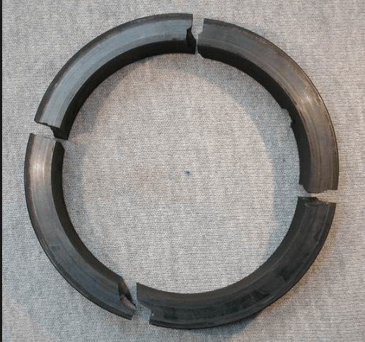
Broken springs are almost always a result of stress corrosion. This happens when stainless steel is flexed in the presence of halogens such as fluorine, bromine, iodine and others. Stress corrosion is actually a chemical attack where small cracks or fissures are created in the stainless steel. Particles can enter this crack and when the springs tries to compress a strong mechanical force is created that can break a spring. Most high-quality industrial mechanical seals have been converted to Hastelloy C springs. Hastelloy C can withstand halogens without cracking. It is interesting to know that springs and metal bellows can actually flex almost indefinitely without breaking if they are flexing within the limits of travel that they were designed for.
Clogged springs indicate that solids in the process flow have accumulated. Seals with multiple small springs are more prone to clog than seals with one large spring or metal bellows.
This chemical incompatibility could be from the process fluid itself. Keep in mind that chemicals become approximately twice as aggressive for every 20 degree rise in temperature. The stuffing box area of a pump can be several hundred degrees F higher than the temperature of the discharge. Additionally, the problem can be a flush fluid or even what a pump is cleaned with. For applications where there is no available elastomer that can handle the chemicals the sealing device will see, you can select a mechanical seal with either PTFE or flexible graphite secondary seals. Neither PTFE nor flexible graphite is a true elastomer. They are considered “plastic” in the sense that when deformed they do not recover their original shape.
Keep in mind that temperature limits published for various O-Ring materials are based on hot air only. These limits are for ultimate failure. Lower temperatures can start the degradation of an elastomer. Again, the temperature in a stuffing box can be hundreds of degrees F higher than at the discharge. Only a temperature gauge connected to the stuffing box, preferably with a tell-tale to indicate the highest temperature reached, can verify how hot the stuffing box gets. The solution for heat is either to reduce the temperature the mechanical seal and its O-Rings actually experience or to select an elastomer with suitable temperature resistance.
Measure the O-Rings from the inside to the outside and from the top to the bottom. This determines the actual deformation. Some deformation is normal. However, if the O-Ring is deformed to where your measurements are at or lower than the nominal dimensions, the O-Ring can no longer seal. Following is some specific dimensional information:
Mechanical seal failures are the most common cause of pump downtime and failure, so mechanical seals and seal support systems must be very carefully designed with components and options selected according to the specific application. However, even high-quality seal support systems can fail unexpectedly for a variety of reasons. When this happens, it’s critical to conduct mechanical seal support failure analysis quickly and accurately, because every minute of downtime results in lost production.
Identifying the failure mode and root cause of a mechanical seal failure allows you to not only correct the immediate problem but prevent it from happening in the future. Thorough mechanical seal support failure analysis can help you understand the conditions under which the seal failed.
In this article, we’ll look at the three most common types of seal support failures—leaks, overheating, and seal failure—what can cause them, and how to prevent them with proactive measures.
Mechanical seals minimize leakage around rotating equipment by creating a “seal” between two very flat surfaces—one stationary and one rotating. These mechanical seal faces inevitably produce some leakage, but the leakage normally evaporates immediately and isn’t a problem. When leaks become noticeable, it’s time to perform mechanical seal support failure analysis to find out why.
When troubleshooting mechanical seal leaks, make note of any unusual noises, damage, or other symptoms accompanying the leak. Use the table below as a starting point to help you identify the cause of the leak.
Overheating indicates either friction between rotating components or excessive fluid temperatures. There are two main reasons mechanical seals overheat: inadequate cooling and excessive friction. Refer to the table below to help diagnose the problem.
As you can see, there is a lot of overlap between the causes of leaks and overheating. Many mechanical seal failure modes can be traced back to the same underlying causes, so be sure to check for leaks as well and use the leak troubleshooting table to investigate.
Excessive heat can eventually lead to heat checking. Mechanical seal heat checking can be identified by fine radial cracks in the seal face caused by excessive stress from the mechanical load and thermal expansion. These cracks may be barely visible to the naked eye, so heat checking can go unnoticed until failure occurs and it’s too late to save the seal. The risk of heat checking increases with high temperatures and high-viscosity fluids like those used in SAGD. It is more common in brittle materials like tungsten carbide.
The same underlying issues that cause leaks and overheating can eventually lead to complete seal failure. A mechanical seal failure likely began as a leak or overheated condition that went unaddressed. The same troubleshooting procedures for leaks and overheating apply, but once the seal has failed, correcting the problem becomes much more difficult. Therefore, it’s important to be proactive and check for problems like leaks and overheating before they cause major problems.
Do you still need help with mechanical seal support failure analysis, or want to learn more about how to be proactive in preventing failures? Field Advisors at Edmonton Valve & Fitting can perform an onsite or remote evaluation to determine the cause of failure and make recommendations on upgrades, component materials, tubing diameters, and instrumentation to help deter mechanical seal failures.
To find out more about how Edmonton Valve & Fitting can help with mechanical seal support failure analysis, contact usthrough our websiteor by calling 780-437-0640.

1. Increase seal chamber pressure if it can be achieved within operating parameters (maintain at a minimum of 175kPa (25psig) above suction pressure)
Note: A review of seal balance requires accurate measurement of seal chamber pressure, temperature and product sample for vapor pressure determination.
Mechanical seal reliability is significantly affected by the operational characteristics of the flush system and its components. In services where the pumped fluid can contain solids, API 610 and API 682 both offer the option of using flush line strainers or cyclone separators.
Flush line strainers can become blocked resulting in immediate seal failure. Cyclone separator effectiveness is dependent on the relative density difference between the fluid and solid particles and the flush line piping (adequate slope for the debris drain line back to the pump suction).
Using an external clean flush, if available, or a dual pressurized seal arrangement will eliminate the need for flush line strainers and cyclone separators and ensure optimum mechanical seal MTBFs.
Flush line strainers and cyclone separators have been the cause of low seal MTBFs (less than 12 months) in many applications where the seal fluid contains solid particles. Eventual modification to a clean external flush or a dual pressurized seal has significantly increased seal MTBFs (greater than 48 months).
This best practice has been used since the 1990s to thoroughly investigate, with the process engineers, the possibility of using a clean external flush source in services where solid particles were contained in the seal fluid. A contingency recommendation where a clean external flush was not available was to use a dual pressurized seal.
In many cases, the additional cost of an external flush or dual pressurized seal was justified on the basis of past plant mechanical seal history and the loss of revenue when the standby pump was under maintenance and the operating pump failed.
The life expectancy of a mechanical seal is determined by a wide variety of factors, most of which are independent from the seal design. Seal selection, installation technique, equipment startup procedure, operation, seal storage conditions, product variables and seal support systems all play a part in how long a seal will last.
Even with so many variables, there are steps users can take to prevent seal failure and increase seal life. Here are four proven methods to ensure any seal operates in peak condition for as long as possible.
Lack of knowledge and information is an obstacle in the seal selection process. Before deciding on a seal, carefully consider the application and normal operating conditions, as well as any potential off-design usage. For example, selecting a seal to operate in hot water may seem easy because the medium is not particularly difficult. However, if the application is boiler feedwater, this assumption is incorrect. Hot water at temperatures above 190 F is unable to appropriately lubricate and cool the seal faces. The sealing process is then compromised by elevated friction between the two mating faces and will culminate in premature seal failure.
To solve this issue, the user must determine if the correct operating parameters are being maintained, then talk with the seal supplier to verify the appropriate American Petroleum Institute (API) flush plan and to choose the correct seal face combination and elastomer materials. Every application has unique requirements, and the proper seals are designed specifically to overcome application challenges.
Seal installation should be performed using the steps outlined by the manufacturer and with great care to avoid damaging the delicate seal faces and/or O-rings. Common issues that may occur when installing a seal include forgetting to tighten set screws before removing setting clips, not tightening gland bolts evenly, damaging O-rings, nicking seal faces or incorrectly using the piping connections. Improper seal installation caused by a lack of knowledge is a significant factor in most seal failures.
Component seal installation is inherently more prone to installation errors when compared with cartridge seals because of the extra steps and measurements needed. This is why, if possible, users should choose a cartridge seal over a component design. There is already enough to be meticulous about when installing a mechanical seal; why add additional opportunity for mistakes?
Excessive heat generation between seal faces will drastically reduce seal life. Dry-running is the most common example of this issue. It typically occurs when a pump is flooded and/or the seal chamber is incorrectly vented before pump startup. Other situations can also lead to excessive heat generation and dry-running.
For example, the seal chamber"s pressure can exceed the seal"s design parameters during upset conditions. In this situation, contact the seal manufacturer. The seal design may need to be altered if condition fluctuations are an ongoing issue.
Shaft runout and elevated vibration levels may cause interruption to the lubrication film established between mechanical seal faces during successful operation. A mechanical seal is often the first visible point of a failure, but the root cause of failure may be located in a different part of the system. Using the correct piping system, verifying sufficient net positive suction head available, carrying out proper pump preparation and ensuring that pump functions are within the original equipment manufacturer"s (OEM) parameters are all important for reliable seal performance.
In another scenario, the process fluid could be unable to properly lubricate the seal faces. This could occur in slurries with a high percentage of solids, media with extremely high or low viscosity, or a process fluid being pumped close to its vapor pressure. The seal manufacturer can help the user choose the best sealing solution based on the specific application and system details.
The use of API 682 flush plans and seal support systems is generally recommended for all applications. Piping plans such as Plan 11 (flush line from pump discharge), Plan 13 (recirculation to pump suction) or Plan 53A (pressurized barrier fluid with a seal reservoir) can be simple or highly complex, but they all have the same goal: to keep the seal faces clean, cool and well-lubricated.
The correct seal support system (based on API 682 flush plans) will have an overwhelming impact on the overall success of production. For example, if abrasives are present in the product, the seal manufacturer may recommend changing a softer carbon face to either silicon carbide or a tungsten carbide face. This hard face combination has proven to be successful in abrasive services. However, if there are no abrasive solids or chemical issues with the process fluid, the carbon versus silicon carbide face may be the best seal face combination to achieve long seal life. In all cases, it is easy to remember: A cool-running seal is a happy seal.
Mechanical seals are composed of many unique parts formed from a variety of materials. Because of the diverse properties and the precise, delicate nature of these components, it is important to understand how long a seal can be stored safely without compromising function.
If the following procedures are followed and the seal is stored in a clean, temperature/humidity-controlled environment, a seal can be stored effectively for five years.
To store a new seal for less than two years, store it in a clean, cool environment. Prevent face lock and loss of face flatness by rotating the seal faces against each other (by rotating the sleeve or shaft) two turns every three months if the seal is not used in operation during that time.
Disassemble the seal and store all parts as individual components. Ensure that O-rings are in a relaxed state and meet the appropriate environmental conditions. For a seal that has been in service, clean and dry all components before storage.
Do not store seal faces (silicon/carbon/tungsten) together in the same packaging. Faces are best separated into individual, protective, bubble-wrapped packages.
These are just a few of the basic recommendations for storage, maintenance and reintroduction to service for a mechanical seal. For more details, see international standards such as Deutsches Institut für Normung (DIN) 7716 and International Organization for Standardization (ISO) 2230, which detail fundamental instructions on the storage and maintenance of elastomeric seal elements.
A facility"s needs are best served when the users capitalize on the seal manufacturer"s knowledge and assistance to choose the right seal for the application. In addition, it is crucial to ensure that the equipment"s operating parameters—such as shaft end and radial play, shaft runout, seal chamber face runout and seal gland register measurements—all fall within the acceptable tolerances as specified by the OEM. Replacing a failed or damaged seal is significantly more costly than taking time at the beginning of the process to ensure the seal is right for the environment.

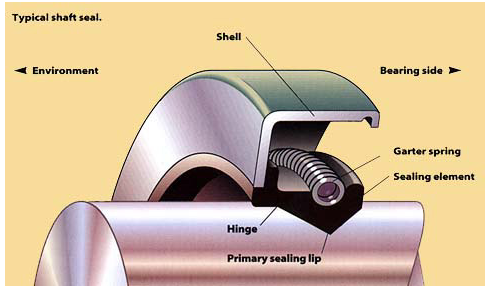
Mechanical sealsare used in pump systems to help join the systems together and prevent leakage of the pumped product, contain pressure, and exclude contamination. A typical system for a simple mechanical seal is comprised of the seal, the stuffing box throat bushing, a liquid flush system, an auxiliary seal and flush, as well as barrier fluid, if necessary. Most modern pump systems are moving more towards mechanical seals as opposed to traditional pump packing and while there are many advantages to using the mechanical method, it does come with its potential failures.
Mechanical seal failure is a common issue, afflicting operators and engineers from many different industries. As with most failures, the most common reason
Before installation, the most critical error that most people make is selecting the incorrect seal for the application. Seals fall into many different
Once you have the correct seal for the application, it’s important to remember that mechanical seals need to operate in a properly controlled environment
cooling systems in place. Mechanical seal faces are incredibly flat making them extremely sensitive to contamination. Even the smallest amount of dirt,
An improperly installed and misaligned seal causes damage to the O-rings and can result in pump vibration, which will cause extensive damage to the equipment
and seals themselves. Vibration can also be the result of pump imbalance or from operating the pump outside of its BEP (Best Efficiency Point). Another
error that is commonly made is using a hammer to pound couplings onto the shaft. Hammers and fragile seal faces do not go well together and continuing
Once the seal has been installed correctly, there are still important points to remember during operation to avoid causing any unnecessary damage. Incorrectly starting the pump can cause the motor to trip and the shaft to twist. This orbital movement will cause the internal parts to contact, resulting in seal failure andbearingwear. Allowing the pump to run dry can also be detrimental to mechanical seals, causing thermal shock and nearly instant shattering. A critical element to using mechanical seals is a coordinating flush plan. Without a flush plan, contaminants build up, causing extreme heat and seal erosion.
To avoid the potential pitfalls mentioned above, look to your trusted, local seal supplier for assistance with selecting the correct seal and for guidance on the best operational and installation practices. AtBearing Centre, we pride ourselves on our superior service and industry expertise. Give us acall today!

Prevention of seal failures through proper design, material selection and maintenance certainly minimizes the risk of failure. Attention to the condition of replaced seals, as well as the equipment performance over time, will result in improved process reliability, reduced operating costs and a safer work environment.
O-ring seals often fail prematurely in applications because of improper design or compound selection. This section is designed to provide the user with examples of common failure modes. By correctly identifying the failure mode, changes in the design or seal material can lead to improved seal performance.
One major factor in possible seal failure is the extreme and harsh environment in which seals are expected to perform. The sealing environment can consist of virtually anything from inert gases at room temperatures to aggressive chemicals at very high temperatures. The sealing environment may result in chemical degradation or swelling of the sealing components. Elevated temperatures may cause seal degradation, swelling or outgassing. And the pressure—or more often, the vacuum environments—can cause outgassing and weight loss.
Analysis of the seal application is crucial to the understanding of possible failure. Most seal design is performed by component suppliers and equipment manufacturers. The designs are refined as experience is gained. As quickly as process technology changes, however, the experience gained with seal design may not be relevant to the latest process technology. Vacuum applications have historically relied on high levels of compression and gland fill to reduce permeation and trapped gases. These techniques, when applied to new materials, or at higher operating temperatures, can result in premature seal failure.
Description:The seal or parts of the seal exhibit a flat surface parallel to the direction or motion. Loose particles and scrapes may be found on the seal surface.
Contributing Factors:Rough sealing surfaces. Excessive temperature. Process environment containing abrasive particles. Dynamic motion. Poor elastomer surface finish.
Description:The seal may exhibit many signs of degradation including blisters, cracks, voids or discoloration. In some cases, the degradation is observable only by measurement of physical properties.
Description:The seal exhibits blisters, pits or pocks on its surface. Absorption of gas at high pressure and the subsequent rapid decrease in pressure. The absorbed gas blisters and ruptures the elastomer surface as the pressure is rapidly removed.
Description:The seal exhibits parallel flat surfaces (corresponding to the contact areas) and may develop circumferential splits within the flattened surfaces.
Description:The seal often exhibits discoloration, as well as powdered residue on the surface and possible erosion of elastomer in the exposed areas.
Contributing Factors:Chemical reactivity of the plasma. Ion bombardment (sputtering). Electron bombardment (heating). Improper gland design. Incompatible seal material.
Description:The seal may exhibit radial cracks located on the highest temperature surfaces. In addition, certain elastomers may exhibit signs of softening—a shiny surface as a result of excessive temperatures.


 8613371530291