
mechanical seal installation price

On the other hand, mechanical seals can become limiting factors in any high-head applications. Mechanical seals can’t run dry, so they’re susceptible to air in the pumping system, and they don’t handle solids well. Cavitation is an issue as any kind of impact, excessive vibration, or excessive heat can harm mechanical seals. Seals also require a different kind of shaft sleeve that’s much tighter. If the pump runs dry, elastomers fail, or contamination enters the system, mechanical seals can fail as a result.
Price —Stuffing boxes are more forgiving and less expensive than mechanical seals. While mechanical seals can range in price from $6,000 to $40,000, stuffing boxes range from $500 to $3,000, depending on shaft size. Expellers can also be more cost-effective than mechanical seals and, since repairing mechanical seals can cost up to 60% of the installation, price is a factor for many.
Maintenance —“Knowing you have a maintenance crew that understands mechanical seals very well and can maintain them properly is another factor,” said GIW Southern Region Manager and slurry pump expert Angela Bryant.
Materials —“There’s a lot of variables that go along when you’re selecting a mechanical seal,” Bryant said. “You’ve got to know temperature, if there’s any chemicals that are going through and what kind of chloride in parts per million is involved so you know what elastomers to use with it. You want to make sure any O-rings in a mechanical seal aren"t going to fail because of the temperature or pH of the materials.”
In addition, mechanical seals don’t handle large particles well and they’ve got to be chemically compatible with the system, so they’re best for thin slurry applications.
“You don’t want anything that’s going to have heavy solids because if the seal faces should open, solids could penetrate and destroy the faces of the ceramic seals,” Bryant said.
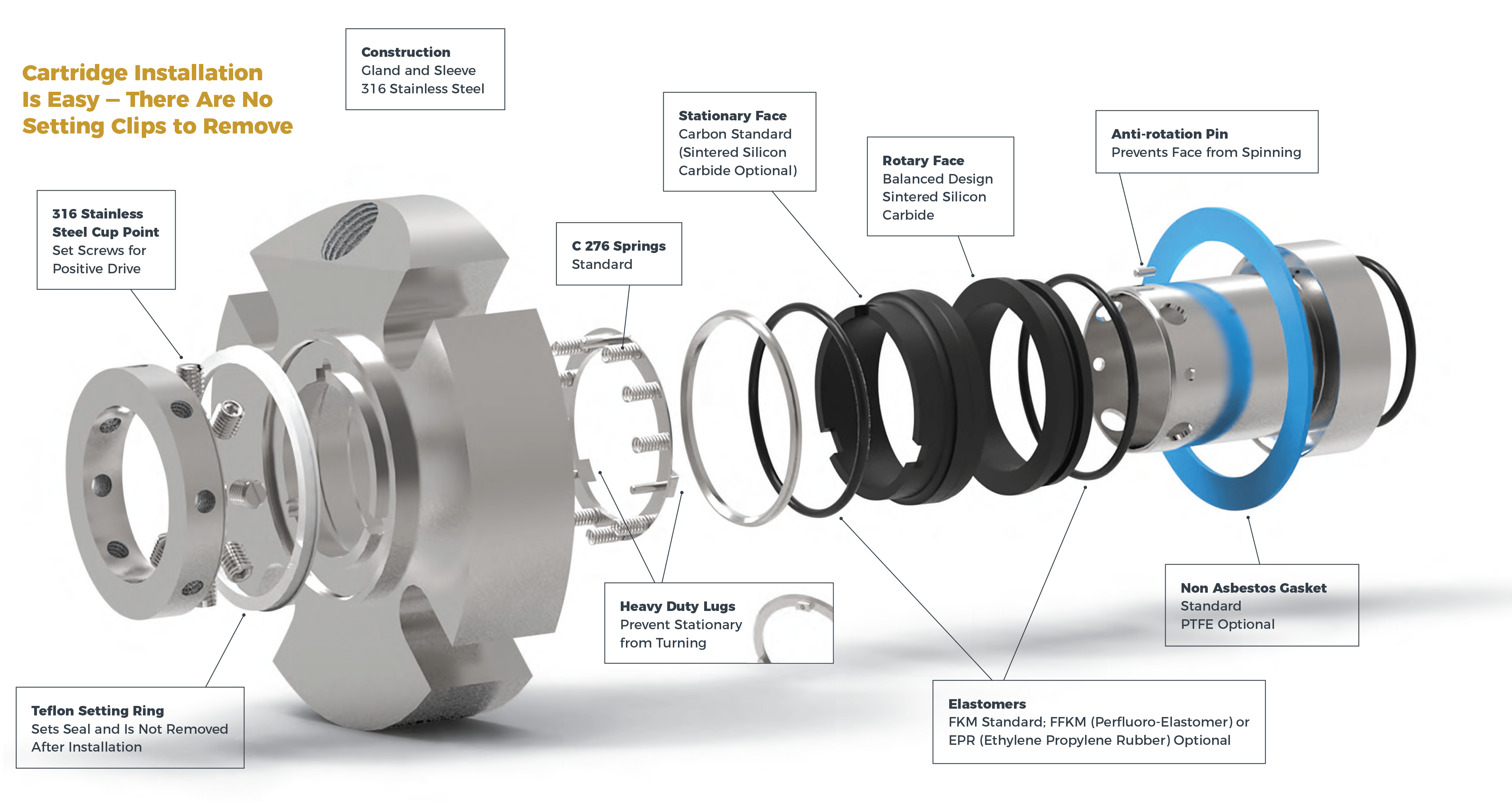
“If installing or replacing a mechanical seal, you’re going to bolt the seal adapter plate to the pedestal, and you’re going to hand-tighten it on,” Bryant explains. “Then, you’re going to locate the seal fit of the adapter of the shaft to make sure it’s centered and everything is concentric. Of course, with mechanical seals, that concentricity has a very close tolerance, much closer than a stuffing box.”
You’ve also got to mount the adapter plate perpendicular to the shaft. Once you’ve got the seal cartridge in, draw it into the adapter on the pedestal evenly by attaching the gland bolts so as not to crack the seal. Check the seal instructions and drawing against the actual parts. Note the location of gaskets and O-rings. Be certain that the locking tabs holding the rotating shaft section of the seal are in place and the fasteners are tight. This keeps the seal faces in contact to prevent damage. Check the fit of the shaft sleeve into the seal bore, and make sure the seal adapter fits into the hub plate or pedestal mounting bore.
Carefully slide the mechanical seal over the shaft sleeve toward the bearing assembly. Do not use any type of tool that could result in impact damage on the seal or any rotating pump part. Move the bearing assembly into position on the pedestal and install the bearing hold-down bolts. Remember that you’ll have to adjust the impeller nose gap later.
Each mechanical seal is equipped with a number of lock tabs to hold the inner section in the proper location during assembly and adjustment. Never rotate the shaft with lock tabs in place. Remove the tabs and store them with their fasteners since they will be required for all future maintenance procedures. If you’re using a quench or lubricating system, install it now.
To adjust the nose gap, install the lock tabs in the seal and then loosen the shaft clamp. This allows the shaft to move axially. Do not rotate the shaft with the faces locked, or it may damage the O-ring between the seal and shaft sleeve. Loosen the bearing assembly hold-down bolts and move it forward carefully until it just contacts the suction plate. Leave one bolt on the drive end snug to keep the housing from tilting. Tighten the shaft clamp, loosen the lock tabs, and rotate the shaft one full turn to verify that the “high spot” is actually making contact.
Before recommending a mechanical seal, the experts at GIW can help you determine if it’s the best shaft seal option for your operation. To see a list of all our offerings and how they can benefit you, check out our Technical & After Sales Services brochure.

FSI Series 1015 mechanical cartridge seals are a premium grade product without the premium price. They"re ideal for use with most ANSI and DIN (standard and big bore) pumps and other types of pumps and rotating equipment. They have the following features:

To improve the performance of any piece of equipment requires a complete understanding of its operation and the effect on its component parts. The definition of mechanical reliability is the probability that a component, device or system will perform its prescribed service without failure for a given time when operated correctly in a specified environment.
A component part is the smallest part that would normally be replaced. A device, such as a pump, compressor, agitator, mixer, etc., is made up of many component parts. A system, such as a process plant, refinery, power plant, ship, etc. is made up of many devices. Thus, when a critical component fails, it can have a tremendous economic impact, not only on the device in which it is installed, but on an entire system. A mechanical seal is just such a component. The major causes for seal failure on a pump are a result of the following conditions:
As the shaft of a pump begins to rotate, a small fluid film develops between the seal faces along with unwanted frictional heat from the seal surfaces in sliding contact. If the amount of frictional heat developed at the seal faces cannot be removed, then the liquid being sealed will flash to a gas or begin to carbonize. Developed frictional heat at the seal faces must be removed.
Each contacting seal has an operating envelope, as illustrated in Fig. 1. The upper limit is determined by wear. More importantly, a seal must operate at a temperature to prevent boiling of the liquid sealed. Operation within the envelope will result in excellent seal life.
Common cryogenic fluids such as argon, nitrogen and oxygen are stored near their atmospheric pressure and pumped near their normal boiling points. These are the most common cryogenic fluids used in industry. The fluids are delivered by over-the-road trucks to industrial users and hospitals. Each truck uses a single stage centrifugal pump driven by a hydraulic motor to move these liquids from the truck to the storage tanks. One fleet operator with 25 trucks began an aggressive program to reduce failures and improve equipment reliability. An analysis of the operation’s seal life and repair costs is shown in Table I. Not only were the maintenance costs excessive, there were also financial losses when deliveries could not be made.
Upon reviewing the seals that failed in this cryogenic service, it became clear that at certain times during the operation of the pump the fluid at the seal faces was flashing and extreme wear and heat checking occurred on the mating ring in the seal assembly. Further complicating the problem was the cool-down period for the equipment. Both the pump and piping had to be cooled down to the liquid gas temperature. Any rise in product temperature could have led to the pump cavitating and the seal running dry.
To be successful in operating near the boiling point of the fluid being sealed requires a seal that eliminates the frictional heat from the sliding services in contact. A seal that is in a controlled environment will allow the liquid to turn to a gas without violent flashing. The properties of the cryogenic fluids to be sealed are given in Table II.
The success from using a non-contacting seal can be explained by reviewing the vapor pressure curve for nitrogen shown in Fig. 2. In this case, nitrogen that is being transported by tank truck is normally at 30 psig/2bar and -320 F/-190 C. When using a contacting seal, the temperature increase at the seal faces is sufficient to start the boiling process at pumping pressure. In an uncontrolled environment such as a contacting seal, continuous flashing damages the seal faces, shortening seal life. During operation of the non-contacting seal design, the temperature rise at the seal faces is only a few degrees, eliminating violent flashing of the cryogenic liquid.
The savings associated with improved seal reliability for the 25 trucks in this cryogenic delivery fleet operation are shown in Table I. These savings were substantial enough to allow the purchase of a new tank truck.
A poor mechanical environment requires a seal to move an abnormal amount during operation. The motion transmitted to a seal can be angular or axial. The most common cause of angular motion is piping stresses transferred to the pump casing. This type of loading will result in premature seal failure.
In one case, a power plant experienced a seal failure every three months. Measurements taken on the pump casing at full operating pressure and temperature indicated 0.016” of deflection. This, in turn, distorted the seal chamber and mating face.
The estimated angular distortion or out-of-squareness at the seal face was greater than 0.012”. The shaft was turning at 1800 RPM. This meant that the seal had to flex 0.012” of travel 1800 times/per minute.
The solution to this problem was to add an expansion joint in the piping in the suction line to the pump, which would eliminate the high load being transferred to the pump casing. Clearly, this failure had nothing to do with the design of the component parts of the seal. The savings per year per pump were estimated to be $18,000.
Axial motion from thermal growth of equipment can cause the seal to run solid, resulting in failure. This is more likely to occur on large pieces of equipment. High thrust bearing wear might be expected on a high-speed boiler feed pump, where, over time, it could lead to seal failure.
A ship’s power plant, with low boiler demands, is a prime example of where axial shaft motion might occur. The greater the wear on the thrust bearing, the more axial travel the seal must handle. When the travel is excessive, the seal will run solid and fail. The cost to the ship’s power plant would be excessive.
A synthetic fuel processing plant implemented a program to reduce maintenance costs and improve the reliability of two large compressors vital to plant operation. The gas compressors can reach process temperatures of 650 F and 370 psia respectively. Steam is used as a buffer fluid to prevent gas in the compressor from reaching atmosphere. Steam pressure is 10 psi above the process gas pressure. At these conditions, steam cutting of the existing sealing surfaces was occurring. Annual maintenance to replace the existing seal was $25,000. Annual bearing repair was $12,500. The annual cost of steam was $100,000.
Review of existing non-contact seal technology determined that it could be redesigned to handle high temperatures. Both compressors were converted to the new technology. Each compressor subsequently operated successfully for 10 years without any major work required. The $2,470,000 in savings over this time period reflected a significant payback from implementation of dry-gas sealing technology for high temperature services. The first compressor will be overhauled this year and the second compressor next year.
As shown by these short case study examples, substantial savings can be achieved by analyzing the reasons for short equipment life and applying the best solution. By the same token, improper specification, application and maintenance of critical components like mechanical seals can lead to reduced reliability and substantial losses for an operation. MT
James P. (Jim) Netzel is an engineering consultant based in Yorkville, IL. His 40+ years of experience in the design and application of mechanical seals includes 20 years of service as chief engineer at John Crane, in Morton Grove, IL. During his career, Netzel has authored (and presented) numerous technical papers through the International Pump Symposium, STLE, ASME, BHRA, AISE, SAE and various trade publications. He also has written chapters on seals and sealing systems for The Pump Handbook, The Centrifugal Pump Handbook and The Compressor Handbook. This article is based on a presentation delivered at MARTS 2008. E-mail: jpnetzel@comcast.net
repair kits keep your Scot Pump in prime condition. Choose a replacement seal or contact us for help finding the right part for your pump. Our Scot Pump product specialists will help you get the right seal at the right price.
We stock mechanical seals and seal kits for all scot pump models. If you need help identifying the seal you need just get in touch and we’re happy to assist.
Mechanical seals are made using both flexible and rigid elements. The combination of materials maintains contact to create a seal at their interface, while allowing the rotating shaft to pass through. A spring or other device is both hydraulically and mechanically loaded to maintain the seal.

A pump which cavitates, has high vibration, or needs an overhaul rather than a seal change is not going to allow a seal to reach its design life of more than 3 yr of continuous service. To obtain maximum seal life, a pump and seal support system must be operating properly.
Modern mechanical seal designs can be extremely cost effective and reliable when installed on correctly sized and maintained pumps. While all of the conditions which must be considered to attain a minimal seal service life cannot be covered, there are typical problems that everyone encounters when installing seals.
Mechanical seals are precision devices, with faces lapped within one micron flatness (Fig. 1). Seals can be very costly, and the installation procedure can determine how much of the dollar value spent is actually realized. With the increase in multicraft personnel doing seal installations, correct procedures become even more important to obtain reliability and value. Poor installation, even with newer cartridge seal designs, is still one of the major causes of short seal life and accounts for up to 20% of seal failures.
The old mechanical seal should be disassembled to determine the cause of failure, unless the causes are obvious. A few minutes taken here can dramatically improve the life of the next installation. Many times, old seals can be field repaired with a kit (Fig. 2). New seals may require installation of different O-ring compounds, based on the failure analysis.
Proper elastomer material choice is essential to seal operation. Temperature limits and chemical compatibility must be checked. Charts are available from seal and O-ring manufacturers. The O-ring selected must be correct for the products being sealed and any cleaners used to flush the system. Be careful to only use the O-ring lubricant supplied with the new seal.
O-ring damage can easily occur. Cutting or nicking is a common problem, especially when the O-ring is compressed in its groove and must slide over holes, snap-ring grooves, key-ways, slots, or threads. Ensure that all surfaces are properly deburred and feel smooth to the touch. It is sometimes possible to cover obstructions with thin tape or plastic wrap to ease installation.
Be certain that O-rings are in their proper position, in grooves or counterbores. Some seal designs have many steps, and the O-ring location may not be obvious. Refer to the installation instructions and drawings or photographs. Silicone grease can be used to keep the O-ring in place when it serves as a gasket. In these cases, a groove is usually machined into the seal gland.
The surface finish on which the secondary seal or O-ring must seal is very important. For a static surface, where there is no relative movement, a maximum of a 45 rms finish can be used. For dynamic surfaces a maximum of 32 rms should be present, and in applications where there is substantial axial movement a finish of 16 rms is preferable. The harder the O-ring durometer, the finer the finish required. Surfaces must be free from defects such as scratches, nicks, and burrs.
Teflon or Teflon encapsulated O-rings are stiff and easily damaged. Placing these O-rings in hot water softens them and facilitates installation. Lubricate them well before installation. Check the orientation of spring-energized Teflon seals because they are typically unidirectional.
Graphite secondary seals must be handled with care. They are fragile and easily damaged; O-rings can be twisted and stretched but graphite rings break. One factor to carefully control is the compression of graphite rings. Very often they are compressed in arrangements which use screws.
It is imperative that the loading be done uniformly to maintain squareness to the shaft on rotary parts and parallelism to the gland on stationary parts. A torque wrench and a dial indicator should be used to maintain squareness and parallelism within the limits specified by the seal manufacturer.
Installation instructions contain a wealth of information. Read the instructions before installing the seal and save the instructions for future reference. They can be useful when a problem arises.
When reassembling the seal, the instructions discuss, at length, a number of precautions to be observed; read and follow them. Don’t force components together; seal faces are easily damaged and expensive to replace. If a seal face or component is damaged it should not be installed.
Work on clean surfaces, with clean hands. Particulates can destroy a seal face in a few revolutions. Take the time to do the installation at a relaxed pace. Do not hurry, as this often leads to tearing the equipment down again.
Be careful when handling the seal, particularly the faces. If the seal is dropped, do not use it. Have the seal vendor check it out thoroughly. If parts do not go together, don’t force them. Measure, check drawings for orientation, and lubricate parts.
Don’t overtighten, which is probably one of the most common mistakes. Never use a “leverage enhancement” method. Wrenches and hex keys are designed for the average person to apply the proper amount of torque to a fastener. Two-bolt glands are easily overtorqued, which distorts stationary seal components and results in face leakage. Overtightening can damage the gasket or cause extrusion, which can also result in leakage.
When installing a noncartridge seal, be certain to use the stationary seal centering shims that are included. If the stationary seal face is not centered, the rotary face can run off of it, shortening seal lie.
Unfortunately, when leaks are encountered the natural tendency is to keep tightening. Instead, try loosening; it often works. The preferred method is to use a torque wrench correctly calibrated in in.-lb. Installation instructions give torque values for gland bolts, set screws, and socket head cap screws.
If there is doubt about anything not being correct, or the seal doesn’t feel right, it’s a good idea to call the manufacturer or the sales representative for help. The seal manufacturer wants to ensure your plant’s success with their product. Calling them two days after the seal started leaking doesn’t help anybody.
Once the seal is assembled, it should be tested. Dual seals are often tested with pressurized air and submerged in water. Seals designed for liquids may let some small bubbles escape past the faces. Slowly rising bubbles between faces are not a problem because liquids do not leak under these circumstances. Bubbles coming from O-rings, through a casting, welding, or a bellows, are not acceptable.
Test for face leakage by rotating the seal by hand. This method usually stops the leak. Put a few drops of water between the faces to verify the integrity of a liquid seal. Use distilled water because tap water leaves mineral residues on the faces once it evaporates. This approach is particularly important if the seal will be stored for several weeks prior to installation.
Although not specifically part of a seal installation, auxiliary equipment installation and placement can have a significant impact on seal performance. Most common problems relate to seal pots/ barrier fluid reservoirs, also referred to as convection tanks.
It is important to place them close to the seal, within 3-5 ft, and at least 1-ft above the seal. Use tubing fit with large radius bends as opposed to piping with a multitude of elbows and other connections. Keep the piping as simple as possible; the more complicated the piping to and from the seal, the poorer the flow of the barrier fluid.
Another common environmental control is a flush, introducing a clean liquid into the seal gland or stuffing box to extend seal life. If installing a flush, determine that it has at least 15-psi more pressure than the stuffing box, and ensure that the flush liquid is properly connected to the correct flush port.
Most balanced seal designs do not require a large volume of flushing; 5-8 gal./hr is normally all that is required for proper heat removal. Unbalanced seals require substantially higher flows. Install a flowmeter/rotometer to visually ensure the flush is entering the seal area (Fig. 3). The flush supply valve should be lockable in the open position.– Edited by Joseph L. Foszcz, Senior Editor, 630-320-7135, j.foszcz@cahners.com
The authors are available to answer questions about seal installation. Henri Azibert can be reached at 617-430-7000, ext. 6697. “Doc” Burke can be reached at 708-596-8400.

Installation or transfer tool is a hollow aluminum cylinder which fits inside the housing protecting the lip seals while mating up to and transferring onto the chamfered / transmission end of your shaft allowing for smooth transition off the tool onto your shaft.

Three variables that most affect the design selection of mechanical seals are: equipmentcharacteristics, application and operating conditions, and the leak rate objective.
The first decision, however, rests in determining if one or multiple seals are required. This often has the potential for a devastating impact on overall performance and reliability.
Relatively clean process fluids with adequate lubricating properties can be contained with a single-seal arrangement. These seals are typically less expensive to install and simpler for teams to operate and maintain. If a separate lubrication system is required, a double seal arrangement will be needed. This will help ensure mechanical seal reliability.
The amount of leakage to atmosphere, which is dictated by the plant’s leak rate objectives and/or regulatory requirements, must be controlled by the seal design chosen. All end-face mechanical seals operating effectively on high-speed applications allow a small amount of vapor to pass through the primary seal interface. Average leakage will be in the 1-cc-per-day range, which is within acceptable tolerances of most process fluids.
Rotating equipmentis the primary application in which end-face mechanical seals can be cost effectively considered and applied. This equipment is used in processing gases, liquids, and slurries.
Cartridge-mounted, end-face seals were primarily introduced for installation on American National Standards Institute centrifugal pumps for making axial shaft adjustments. Their simplicity and ease of installation and maintenance makes cartridge-mounted single and dual units a strong choice for rotating equipment with a stuffing box or seal chamber in which a gland can be installed.
Air seals use a knife of air to seal the process instead of seal faces. They are primarily installed on rotating equipment used to move or mix powders, bulk solids, or heavy slurries.
One factor stands out as the primary cause of premature seal failure — application. This involves defining the conditions inside the seal chamber, which dictate how long and how well the seal performs. Once these conditions are known, the best seal design for the conditions should be selected.
Extending the life of end-face mechanical seals primarily depends on clean and cool operation, which is directly affected by the application.Misapplication of materials of construction is a common error that rapidly leads to premature seal failure. For example, process fluids that are sticky, such as glue, molasses, and paint, can bind the faces together.
Every application, process fluid, and change in the environment adds a new and often unconsidered mix of consequences, which is why the application has such a tremendous impact on seal reliability.
Once the seal design best for the application is selected, precision installation follows. Many seal failures occur because the personnel incorrectly installed the seal. If installing a component seal, an experienced technician should be the installer. Cartridge seals are simpler to install, but errors still occur. Follow the manufacturer’s instructions carefully. If external barrier fluid will be used, ensure that the environmental controls are set up correctly. Correct setup allows for the proper pressure of the barrier fluid into the stuffing box and adequate cooling of the fluid.
Many steps are required to carry out precision installation. The major steps for most cartridge mechanical seals are:Preinstallation check list (including equipment inspection and cleaning)
Inspect and empty the stuffing box, correcting any holes, burrs, or sharp edges and ensuring that adequate space is available to adequately fit the seal assembly
Defining how a mechanical seal will be used and its environment is critical for optimal operation and life. Often, seal environmental controls are over looked, resulting in shorter seal life. Even with the ideal design and precision installation, problems may arise. Any hostile operating conditions or changes in the process parameters can override the capabilities of the design and materials, thereby reducing reliability. To obtain optimal seal life, the seal should be operated and maintained as designed.
One example can be found in wastewater treatment plants where raw sewage must be moved with high-speed centrifugal pumps. These water-based solutions are entrained with solids that can hang up the seal and quickly erode the selected materials if the slurry migrates between the faces.
Flush water from an external source is a common solution for preventing premature failure. It floods the seal cavity with a clean, cool water. This flush must be maintained at a higher pressure than the wastewater because it provides a clean, cool environment that is essential for safeguarding the life of the mechanical seal. These single-seal systems operating properly will increase water consumption and will also dilute the pumped product.
In some facilities, water consumption may be a primary concern or process dilution cannot be tolerated. For these situations, a dual-seal system operating with an independent, clean-liquid flush will be required.
Other environmental factors, such as temperature and pressure, must also be carefully controlled to prevent leakage. Careful attention should be given to the environmental control systems specified for sealing hazardous or toxic fluids. They must meet the allowable leakage tolerances for the fluid being sealed and prevent excessive leakage in case a seal fails.
Mechanical seals prevent pumps from leaking by containing the pressure of the pumping process. They withstand the friction caused by the pump shaft rotating. This results in less wasted product, more cost savings, and less clean up.

The drive to reduce costs and environmental concerns have caused many design and processing engineers to turn to perfluoroelastomer sealing parts as the most cost-effective sealing solutions. The value-in-use of perfluoroelastomer can be proven in operating conditions where conventional elastomers fail. Even under less arduous conditions, DuPont Kalrez perfluoroelastomer seals can be the best solution, as they can last significantly longer than conventional sealing solutions.
When considering the economics of elastomeric seals, it is vital to look beyond the total cost related to the sealing solution. The total system cost in use is the sum of the cost of the O-ring seal plus the installation cost plus the downtime cost (including loss of productivity through leakage and clean-up costs).
The following case studies highlight the total system cost comparison. They take into consideration the frequency and cost of seal replacement as well as the attendant downtime cost.
In this situation the seals are not being replaced, as they last for the life of the pump or the equipment. Strictly on a cost basis, perfluoroelastomers cannot be justified.
This is a situation in which seals need to be replaced for failure or maintenance reasons once or twice during the life of the equipment, introducing the added factor of downtime cost each time the seal is changed. Using DuPont Kalrez perfluoroelastomer seals could be the most cost-efficient solution.
In this situation, seals need to be replaced several times. Using a conservative estimate of service life of perfluoroelastomer seals being four times that of conventional sealing material, the replacement and downtime costs associated with repeated, multiple replacements of existing seals far outweigh the initial higher costs for perfluoroelastomers. In addition, the unplanned replacement of existing seals would further increase downtime costs, as well as having other, possible serious, effects.
When seal are replaced on a regular basis rather than waiting for them to fail -- for reasons of safety, service, quality or economy -- the downtime costs incurred in replacing the existing seals are usually constant. The added expense of switching to DuPont Kalrez perfluoroelastomer seals should be offset by doubling periods between overhauls. In certain cases, this period could be tripled or quadrupled.
Manufacturing facilities continually strive to extend time between maintenance to reduce costly downtime. The example below shows costs related to a standard, cartridge, dual mechanical seal for the chemical process industry. Even with a relatively low 20 percent seal replacement rate over the lifetime of its assembly, savings could be realized from using DuPont Kalrez parts.
The second example below, on O-rings installed in couplings, shows that the lifetime of the O-ring has an even more dramatic impact on cost savings. Of course, each plant has its unique replacement rate and downtime cost. The chemical environment influencing the choice of the sealing material used must be considered when evaluating the potential savings from using DuPont Kalrez seals in an assembly.
Application 1: O-ring seals fitted to product filling line, processing solvents, surfactants and concentrated herbicides at temperatures ranging from 10°C to 45°C, and pressures from 1.5 to 3.5 bars Eff.
We hope this case study has been useful. We also want to take this opportunity to alert you to a special webinar next month, a joint effort of Gallagher Fluid Seals and Freudenberg.
*Downtime costs; without an in-line spare pump=$3,000 an hour, no downtime cost with an inline pump. Cost takes into account a pump going down, process shutting down, two hours to replace a seal, getting the process lined out and running again.

Recently we received a call from a customer. He was attempting to install a mechanical seal and had broken two of them. After a short discussion with one of our service technicians, it became clear that the customer was demonstrating a classic example of how to kill a mechanical seal, not using the correct lubricant.
When I heard about this, I asked the service technician to tell me more. I asked him to share with me the top 5 ways he has seen mechanical seals go down due to installation. He did not disappoint.
Mechanical seals are easily damaged during installation. That’s why it’s imperative to read the installation instructions carefully before attempting to install the seal. See photo here. The installation instructions stated to remove the spacers before starting the unit. The spacer became lodged in the seal, damaging internal components.
Pump misalignment is caused by pipe strain, deflection during a hard start, shaft run out, or a myriad of other scenarios. Misalignment puts undue stress on mechanical seal components, causing them to not function properly, wear prematurely, and potentially fail.
Be sure to follow proper installation guidelines and use laser alignment tools to ensure the pump (and ultimately the mechanical seal!) is set up for success.
Lubrication is necessary for proper mechanical seal installation. Lack thereof can damage o-rings or rubber bellows on the seal, causing them to tear, or roll. There are many options available, from petroleum jelly, to silicon grease, to special lubricants. Always check the installation instructions to ensure the lubrication you choose is compatible with seal components and the product pumped.
Dirt on the seal face, even oil from finger prints, can set a mechanical seal up to fail. Tiny particles can create wear and destroy seal faces, causing leakage.
This is probably one of the most common mistakes. Over-tightening fasteners can cause seal components to become distorted and leak. Oftentimes when a seal starts to leak, the natural reaction is to tighten even further! Unfortunately this just exacerbates the problem. Instead, try loosening a bit, the problem may correct itself, if the internals haven’t broken already from mechanical shock.
After reviewing this list of 5 ways to kill a mechanical seal, the service technician I worked with on this said he could come up with many more ways. Maybe that will be a follow up post. How have you seen a mechanical seal go down? Let me know in the comments!
Not sure why your mechanical seal is failing? Ask us about it! We gladly provide technical assistance to businesses and municipalities in Wisconsin and upper Michigan.
Mechanical seals come in different configurations, and each variant has its advantages and disadvantages. Among the most common variants are component mechanical seals and cartridge mechanical seals.
When selecting a mechanical seal type, pump users must consider the cost of installation, long term running costs, pump characteristics, and the anticipated operational conditions (heat, vibration, and pressure). Keep your technical staff in mind as well, because having a skilled technician on-hand for regular maintenance vs. having to outsource maintenance and repairs makes a significant difference.
A cartridge mechanical seal is a completely enclosed seal system with preassembled components. Typically, this seal type is composed of a gland, sleeve, and other hardware that make pre-assembly possible.
Component mechanical seals are composed of separate dynamic and stationary parts. Unlike cartridge seals, component seals are not preassembled and require skilled technicians to install them. Incorrect installation of seal faces, O-rings, and seal axial setting on the pump shaft will result in reduced seal life or in some cases, immediate seal failure.
The major cons for non-cartridge mechanical seals are their susceptibility to damage. Other than cartridge type seals that are completely encased within secure housings, component mechanical seals usually have exposed parts that are more susceptible to damage during transportation or installation.
Further, non-cartridge type seals require precise measurements during installation to prevent seal failure. Properly installing this type of seal requires more operator time and thus a higher cost to install or re-install after a repair.

The scope of our mechanical seal product range far exceeds any other seal manufacturer. From small elastomer bellows seals used in millions of domestic water pumps to double mechanical seals that ensure maximum sealing safety and large, highly customized dry-running gas seals for mission critical high speed turbo compressors, John Crane has the right product for any application.
Our world-class rotating equipment technologies, paired with an unmatched breadth of applied engineering expertise, meet virtually all international standards including API 682 and help plants reduce maintenance costs, slash down time and improve reliability. When it comes to keeping your rotational equipment running 24/7, John Crane’s comprehensive range of mechanical seals and systems has you covered.
A range of seals for mission-critical applications, designed to solve the application-specific challenges of each industry. From API 682 compliance for the oil and gas industries, using gas seal technology on our innovative pump gas seals to eliminate fugitive emissions, dealing with slurry in the mining and minerals processing industries, to the difficulties associated with maintenance on large pumps and rotating equipment — we have a solution.
Dry-running, non-contacting gas seals have been the industry standard since the early 1980s for turbomachinery. John Crane gas seals, separation seals and support, monitoring, control and conditioning systems — the heart of any reliable sealing solution — are constantly evolving to meet the needs of customers. The product portfolio is supported by unrivaled global service capability providing repair, retrofit, gas seal storage and reliability expertise, delivering total solutions throughout the product lifecycle.
In industries like chemical, pharmaceutical, pulp and paper, and food and beverage, safeguarding and compliance with industry standards, avoiding contamination and efficiency are always top priorities. Our range of vessel and agitator seals optimize equipment performance, maintain product purity and conform to industry regulations, no matter where you are.
Our range of mechanical seals, packing and bearing isolators combines advanced, thoroughly proven technologies with extensive industry expertise to create a range of products characterized by innovative design concepts and outstanding manufacturing quality. Tried, tested and effective solutions for virtually any application that deliver robust performance, reduced installation times and lower maintenance costs.
Create the optimum operating environment that will ensure outstanding seal performance and reliability. Our comprehensive range of engineered pressure reservoirs, gas seal control panels, heat exchangers and abrasive separators can be combined to produce the perfect seal support system for any application.
Designed to overcome rigorous challenges, our comprehensive suite of seal face technologies combat limited seal face lubrication that adversely affects reliability, cost and durability. Our engineers designed these face treatments to extend rotating equipment life through advanced micro machined patterns and features improving seal face lubrication that optimizes equipment performance. We deliver the right face technology for the right application.

One of the most common questions we get through the phone or through email is how to fix a leaky pump. The answer to that will of course depend on where the leak is located, but for leaks that happen in the middle of the pump or is located in the middle of the motor and the impeller (a dead giveaway is a leak coming from the vents of your motor) then it’s 99% that it’s a mechanical seal problem and you will need to replace it as soon as possible.
Now why do we need to replace it ASAP? Well, it’s simple. While your pool pump deals with water all the time, your pool pump water must be kept dry at all times! A leaky seal is actually a blessing in disguise, it gives you a tell-tale sign that maintenance is required. It’s better than a complete seal failure with no warning right?
Aside from opening up your pump and checking the mechanical seal manually, the best way to determine which mechanical seal to use is to get the part number from the user"s manual. If you don"t have your manual then don"t worry, just shoot us an email at the contact form at the bottom with your pump brand and model and we"ll sort out what seal is best for your pump.
Now that the impeller is off, we can now see the two parts of the mechanical seal. The white part should be attached to the seal plate while the black spring part is attached to the impeller. Remove the old mechanical seals by pushing them out with your hands. If they’re stuck, a rubber mallet can help, use something like the head of a screwdriver to push against the existing seal and give it a couple of gentle taps with a rubber mallet to pop them out.
Many people would just pop in the new mechanical seals, close it up and call it a day. But really, why rush? Since it’s already there, take a couple of minutes to inspect your impeller and clean it up properly. See if anything is stuck inside and for wear and tear. If you do spot any signs of damage, then make sure to note down your impeller model and order a replacement in advance, just in case.
Very Important: Wear gloves when handling the new seals. Oils from our hands (human body oils) can cause deterioration to the seals and may lead to premature damaging and leaking in the future. Did you take note of the way the seals were seated before popping them out? Well, if you didn’t, don’t worry! Here’s how they’re put together.
Lubricate the white porcelain seal half on the rubber cup on the ceramic seat. Once that’s all nice and lubed up, gently push it into the seal plate, white side up. Set aside.
Once the mechanical seals are in, reattach the seal plate and the impeller. Again, secure the pump shaft with a 7/16” wrench then screw in the impeller clockwise. Don’t forget to re-secure the capacitor before closing up the back of the motor. Reassemble everything (don’t forget the diffuser!) and slide the motor assembly back into the pump body. Screw everything back in place, (don’t overtighten even if you’re tempted to do so! Overtightening can cause cracks which can lead to permanent damage) and reattach all of the electrical fittings. Once done, you can reopen the valves and that’s it! You’re done!
Sometimes a mechanical seal doesn"t give you warnings and will fail on you causing catastrophic flooding of your pool pump motor. Now, you can always replace the motor itself, but we don"t recommend that. A couple of reasons why we don"t recommend simply replacing the motor when a a mechanical seal fails are the following:
A sudden mechanical seal failure can also be a symptom of something else wrong in the pump (excess vibration and other problems) and it may happen again to your brand new motor.
In cases of mechanical seal failures causing motor failture, we recommend to simply replacing the whole pump itself, that way you"ll be assured that the failure doesn"t reoccur anytime soon, plus you"ll have the peace of mind of a brand new warranty just in case. Browse our collection of pool pumps by clicking the button below.
Replacing a mechanical seal takes about 2 minutes and the part only costs a few dollars, what takes time is taking everything else apart. But this little maintenance trick will save you hundreds, if not thousands of dollars down the line so when you see your pump leaking near the middle or near the motor part, get yourself a new mechanical seal and fix it asap!


 8613371530291