
agitator mechanical seal design pricelist
In industries like chemical, pharmaceutical, pulp and paper, and food and beverage, safeguarding and compliance with industry standards, avoiding contamination and efficiency are always top priorities. You can use John Crane’s range of mixer and agitator mechanical shaft seals for reaction vessels to optimize safety and equipment performance, and conform to industry regulations, no matter where you are. Modern dry running mechanical seal technology and optional hygienic design features maintain product purity in mission-critical pharmaceutical applications.
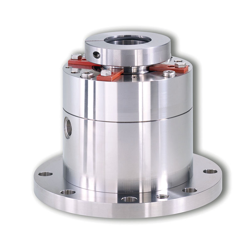
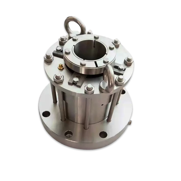
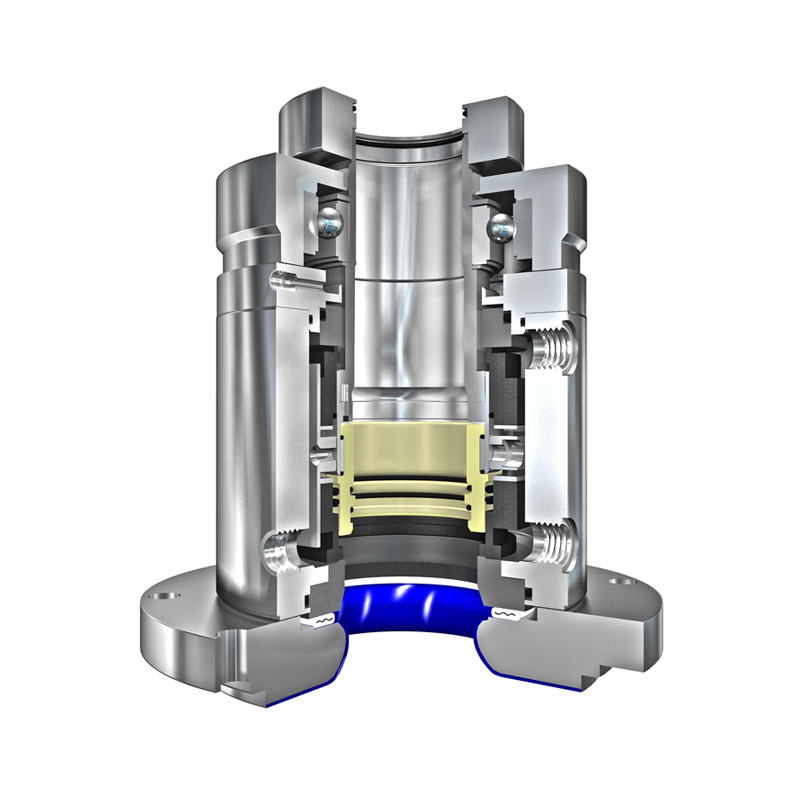
The first choice for ultra-clean pharmaceutical and biotechnology applications, Type 5280 vessel seals apply Qualified Hygienic Design (QHD) and GMP standards and guidelines to enable the cleaning and sterilization of the product wetted process area with the seal in place (CIP, SIP). Due to the rotating seat design, the inboard sealing components protrude into the vessel, making them accessible for cleaning and/or sterilization devices installed in the reaction vessel. To avoid recontamination of the process vessel via the applied barrier fluid, a steam sterilization of the seal"s barrier room is feasible on request. The rotating seat design allows for application to top, side, or bottom entry mixers or agitators as well as products with a higher viscosity or solid content. This makes the seals a perfect solution for special equipment such as dryers or process filters.
Due to their modular design concept, Type 5280 seals are available in liquid-lubricated (5280 W), gas-lubricated (5280 G) and dry-running (5280 D) versions as well as a unique gas/dry face combination (5280 GD). Advantages of contacting dry-running seals include freedom from contamination by barrier liquid and a low face wear rate together with a cost-efficient, easy-to-install (gas) supply system. Advantages of gas-lubricated versions (G, GD) include the non-contacting and wear- and particle-free operation. The GD design reduces the overall barrier gas consumption compared to G version.
Type 5280 is part of a seal family consisting of different seal types that are suitable for different vessel materials: Type 5280 for steel, Type 5281 for glass-lined and Type 5282 for special alloy vessels.
Mixer and agitator mechanical seal designs with vibration-isolated faces which withstand conditions of drag and shear that destroy common seals. Our mixer / agitator seals also offer excellent motion tolerance and instant pressure shift capabilities.
Double-acting liquid-lubricated mechanical seals are the most common type for mixing applications. These seals can be used under nearly all operating conditions in a mixing vessel. They can also be designed as a gas-lubricated version in which a continuous supply of gas into the seal chamber maintains a marginal gap, thus preventing wear of the seal rings.

The use of the word “seal” is a misnomer; as a mechanical seal is a restrictive flow path,that is either an angular or radial gap.The flow through this gap is generally so low it goes unnoticed if a liquid or inconsequential if a gas.
A mechanical seal works byretaining a liquid or gas inside a rotating piece of equipment. Mechanical seals can be designed to prevent contamination of the process by the environment and prevention of leakage of the process into environment.
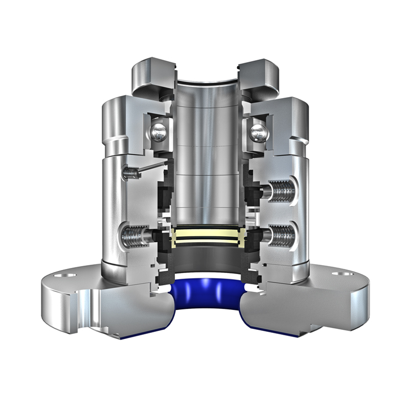
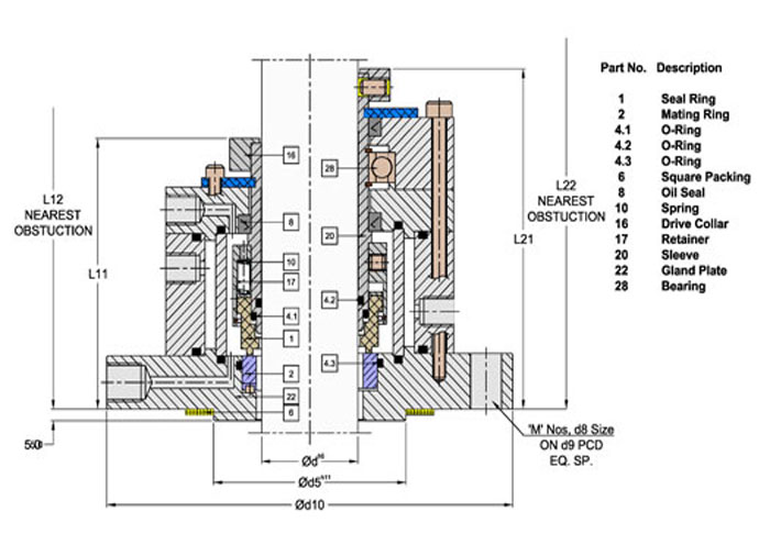
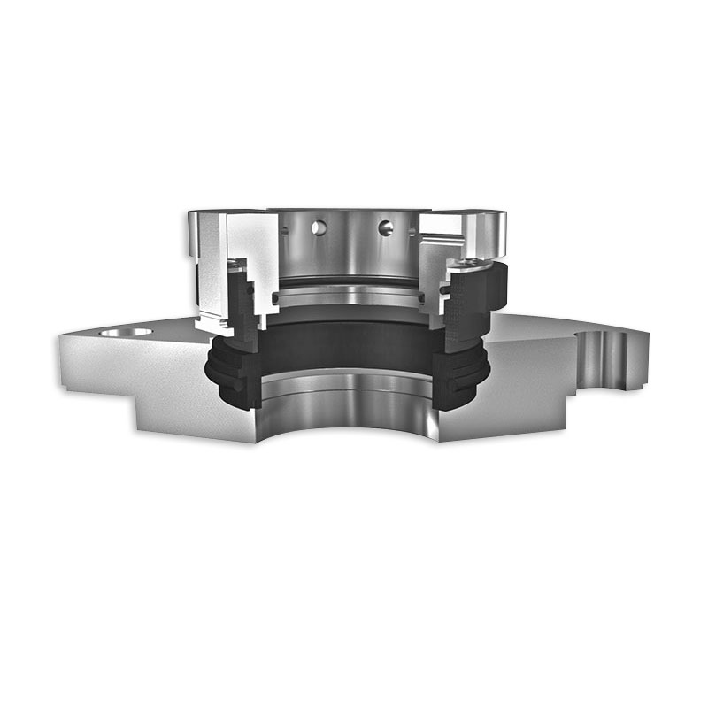
The basic components of a mechanical seal are a Rotating Part and a Stationary Part. The primary seal of a mechanical seal consists of a rotating face and a stationary face. The faces are kept lubricated by maintaining a thin film of fluid between each face. There is a very small gap between these 2 components which creates a restrictive flow path.
There are other components namely o-rings or gaskets which are used as secondary seals and hardware which is used to support the seal faces and to attach them to the rotating part (i.e shaft) and stationary part (i.e cover plate).
The primary seal of a mechanical seal is made up of 2 seal faces where these two parts meet is where the seal gap is located. The mating surface of the seal face is machined to a very tight tolerance.
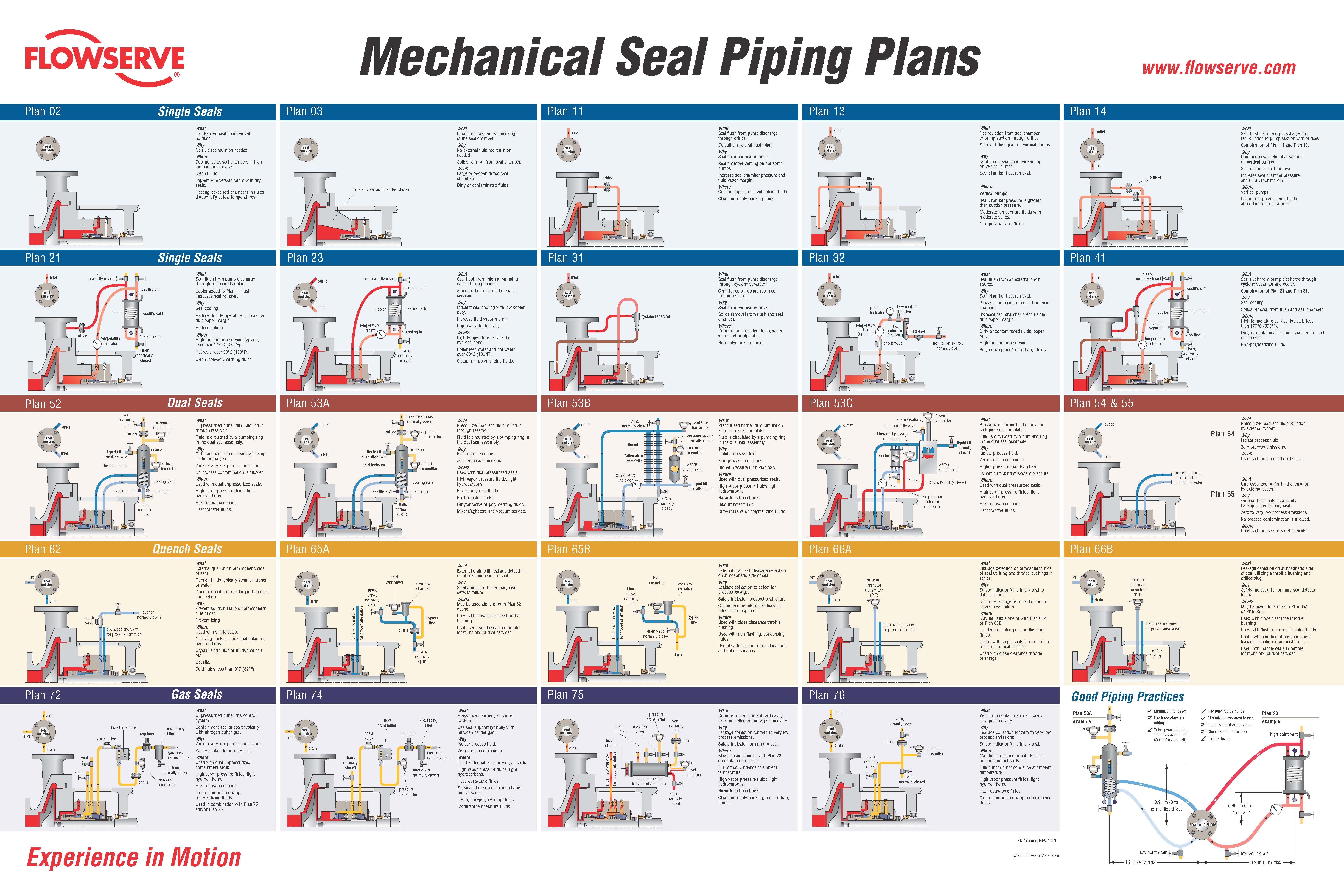
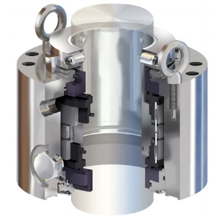
Double Seal (Barrier) => consists of two primary seals in various arrangements. There is a barrier fluid between the two primary seals which is at a higher pressure than the process. There is always some leakage of the barrier fluid in process & out to atmosphere. As long as barrier pressure is maintained there is no leakage of process to atmosphere or contamination of process by environment.
Double Seal (Barrier) – Wet => is a double seal where the barrier is a liquid. It is generally the most robust seal. It has a good pressure, speed and temperature capabilities.
Gas Contacting Seal– the seal faces are in contact, the soft face wear acts as a lubricant. Low pressure, speed and temperature capabilities and possibilities of wear getting into the process.
Gas Non Contacting Seal – the seal faces are NOT in contact. They are kept apart by a flow of gas between the faces. Good temperature, speed and pressure capabilities. If operated correctly their is no wear but care must be taken in order to minimise shaft run out.
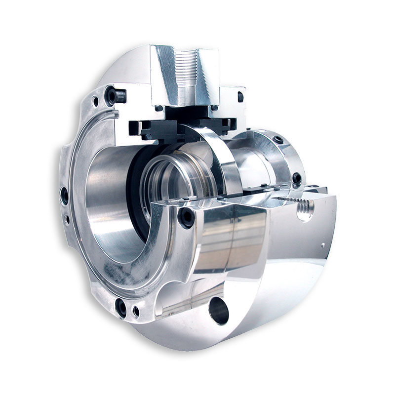
Cartridge seal =>is where the rotating and the stationary hardware are pre-assembled before mounting onto the pump/mixer. Cartridge seals are much easier to fit & maintain compared to the component seal.
A lip seal is a specific type of seal, it is a radial seal, where the part that seals against the rotating surface is a narrow cross section, soft material i.e the lip and it is made from an elastomer or non-elastomer material with a backup spring. Most commonly used to seal bearings in Mixers/Agitators. A lip seal rotates too quickly to be used on pumps.
Abarrier fluid is any gas or liquid which is used to pressurise a double mechanical seal. It must be compatible with the process, generally non-toxic and a good lubricant.
Please consult the pump manufacturer/distributor for guidance on these calculations for mixer seals, the barrier pressure is set at a certain value above the maximum vessel pressure.
Packing is a material that is stuffed between a rotating shaft and a stationary part gland to maintain pressure. Packing is a low cost alternative to mechanical seals.
We supply mechanical seals into the pharmaceutical, bio-technology, chemical processing, mineral and ore processing, semi-conductor and general industries.
Depending on your particular application, if you are looking mechanical seals to suit a pump application; Mechanical Seal for Pumps, or if you are trying to source mechanical seals for an agitator or tank mixer; Mechanical Seal for Agitator, or perhaps you have a hygienic application in mind, take a look at our range of Mechanical seal for Hygienic & Aseptic applications.
Our Mechanical Seal specialists can advise you on the appropriate selection of a seal support system which will deliver years of reliable service and operating cost savings in the longer term.
If you have any query around how to install mechanical seals or have some concerns around seal failures, why not contact one of our seal specialists below to discuss it in more detail and find out how we can help solve your issues and get your process running reliably again.
To improve the performance of any piece of equipment requires a complete understanding of its operation and the effect on its component parts. The definition of mechanical reliability is the probability that a component, device or system will perform its prescribed service without failure for a given time when operated correctly in a specified environment.
A component part is the smallest part that would normally be replaced. A device, such as a pump, compressor, agitator, mixer, etc., is made up of many component parts. A system, such as a process plant, refinery, power plant, ship, etc. is made up of many devices. Thus, when a critical component fails, it can have a tremendous economic impact, not only on the device in which it is installed, but on an entire system. A mechanical seal is just such a component. The major causes for seal failure on a pump are a result of the following conditions:
As the shaft of a pump begins to rotate, a small fluid film develops between the seal faces along with unwanted frictional heat from the seal surfaces in sliding contact. If the amount of frictional heat developed at the seal faces cannot be removed, then the liquid being sealed will flash to a gas or begin to carbonize. Developed frictional heat at the seal faces must be removed.
Each contacting seal has an operating envelope, as illustrated in Fig. 1. The upper limit is determined by wear. More importantly, a seal must operate at a temperature to prevent boiling of the liquid sealed. Operation within the envelope will result in excellent seal life.
Common cryogenic fluids such as argon, nitrogen and oxygen are stored near their atmospheric pressure and pumped near their normal boiling points. These are the most common cryogenic fluids used in industry. The fluids are delivered by over-the-road trucks to industrial users and hospitals. Each truck uses a single stage centrifugal pump driven by a hydraulic motor to move these liquids from the truck to the storage tanks. One fleet operator with 25 trucks began an aggressive program to reduce failures and improve equipment reliability. An analysis of the operation’s seal life and repair costs is shown in Table I. Not only were the maintenance costs excessive, there were also financial losses when deliveries could not be made.
Upon reviewing the seals that failed in this cryogenic service, it became clear that at certain times during the operation of the pump the fluid at the seal faces was flashing and extreme wear and heat checking occurred on the mating ring in the seal assembly. Further complicating the problem was the cool-down period for the equipment. Both the pump and piping had to be cooled down to the liquid gas temperature. Any rise in product temperature could have led to the pump cavitating and the seal running dry.
To be successful in operating near the boiling point of the fluid being sealed requires a seal that eliminates the frictional heat from the sliding services in contact. A seal that is in a controlled environment will allow the liquid to turn to a gas without violent flashing. The properties of the cryogenic fluids to be sealed are given in Table II.
The success from using a non-contacting seal can be explained by reviewing the vapor pressure curve for nitrogen shown in Fig. 2. In this case, nitrogen that is being transported by tank truck is normally at 30 psig/2bar and -320 F/-190 C. When using a contacting seal, the temperature increase at the seal faces is sufficient to start the boiling process at pumping pressure. In an uncontrolled environment such as a contacting seal, continuous flashing damages the seal faces, shortening seal life. During operation of the non-contacting seal design, the temperature rise at the seal faces is only a few degrees, eliminating violent flashing of the cryogenic liquid.
The savings associated with improved seal reliability for the 25 trucks in this cryogenic delivery fleet operation are shown in Table I. These savings were substantial enough to allow the purchase of a new tank truck.
A poor mechanical environment requires a seal to move an abnormal amount during operation. The motion transmitted to a seal can be angular or axial. The most common cause of angular motion is piping stresses transferred to the pump casing. This type of loading will result in premature seal failure.
In one case, a power plant experienced a seal failure every three months. Measurements taken on the pump casing at full operating pressure and temperature indicated 0.016” of deflection. This, in turn, distorted the seal chamber and mating face.
The estimated angular distortion or out-of-squareness at the seal face was greater than 0.012”. The shaft was turning at 1800 RPM. This meant that the seal had to flex 0.012” of travel 1800 times/per minute.
The solution to this problem was to add an expansion joint in the piping in the suction line to the pump, which would eliminate the high load being transferred to the pump casing. Clearly, this failure had nothing to do with the design of the component parts of the seal. The savings per year per pump were estimated to be $18,000.
Axial motion from thermal growth of equipment can cause the seal to run solid, resulting in failure. This is more likely to occur on large pieces of equipment. High thrust bearing wear might be expected on a high-speed boiler feed pump, where, over time, it could lead to seal failure.
A ship’s power plant, with low boiler demands, is a prime example of where axial shaft motion might occur. The greater the wear on the thrust bearing, the more axial travel the seal must handle. When the travel is excessive, the seal will run solid and fail. The cost to the ship’s power plant would be excessive.
A synthetic fuel processing plant implemented a program to reduce maintenance costs and improve the reliability of two large compressors vital to plant operation. The gas compressors can reach process temperatures of 650 F and 370 psia respectively. Steam is used as a buffer fluid to prevent gas in the compressor from reaching atmosphere. Steam pressure is 10 psi above the process gas pressure. At these conditions, steam cutting of the existing sealing surfaces was occurring. Annual maintenance to replace the existing seal was $25,000. Annual bearing repair was $12,500. The annual cost of steam was $100,000.
Review of existing non-contact seal technology determined that it could be redesigned to handle high temperatures. Both compressors were converted to the new technology. Each compressor subsequently operated successfully for 10 years without any major work required. The $2,470,000 in savings over this time period reflected a significant payback from implementation of dry-gas sealing technology for high temperature services. The first compressor will be overhauled this year and the second compressor next year.
As shown by these short case study examples, substantial savings can be achieved by analyzing the reasons for short equipment life and applying the best solution. By the same token, improper specification, application and maintenance of critical components like mechanical seals can lead to reduced reliability and substantial losses for an operation. MT
James P. (Jim) Netzel is an engineering consultant based in Yorkville, IL. His 40+ years of experience in the design and application of mechanical seals includes 20 years of service as chief engineer at John Crane, in Morton Grove, IL. During his career, Netzel has authored (and presented) numerous technical papers through the International Pump Symposium, STLE, ASME, BHRA, AISE, SAE and various trade publications. He also has written chapters on seals and sealing systems for The Pump Handbook, The Centrifugal Pump Handbook and The Compressor Handbook. This article is based on a presentation delivered at MARTS 2008. E-mail: jpnetzel@comcast.net

The use of the word “seal” is a misnomer; as a mechanical seal is a restrictive flow path,that is either an angular or radial gap.The flow through this gap is generally so low it goes unnoticed if a liquid or inconsequential if a gas.
A mechanical seal works byretaining a liquid or gas inside a rotating piece of equipment. Mechanical seals can be designed to prevent contamination of the process by the environment and prevention of leakage of the process into environment.
The basic components of a mechanical seal are a Rotating Part and a Stationary Part. The primary seal of a mechanical seal consists of a rotating face and a stationary face. The faces are kept lubricated by maintaining a thin film of fluid between each face. There is a very small gap between these 2 components which creates a restrictive flow path.
There are other components namely o-rings or gaskets which are used as secondary seals and hardware which is used to support the seal faces and to attach them to the rotating part (i.e shaft) and stationary part (i.e cover plate).
The primary seal of a mechanical seal is made up of 2 seal faces where these two parts meet is where the seal gap is located. The mating surface of the seal face is machined to a very tight tolerance.
Double Seal (Barrier) => consists of two primary seals in various arrangements. There is a barrier fluid between the two primary seals which is at a higher pressure than the process. There is always some leakage of the barrier fluid in process & out to atmosphere. As long as barrier pressure is maintained there is no leakage of process to atmosphere or contamination of process by environment.
Double Seal (Barrier) – Wet => is a double seal where the barrier is a liquid. It is generally the most robust seal. It has a good pressure, speed and temperature capabilities.
Gas Contacting Seal– the seal faces are in contact, the soft face wear acts as a lubricant. Low pressure, speed and temperature capabilities and possibilities of wear getting into the process.
Gas Non Contacting Seal – the seal faces are NOT in contact. They are kept apart by a flow of gas between the faces. Good temperature, speed and pressure capabilities. If operated correctly their is no wear but care must be taken in order to minimise shaft run out.
Cartridge seal =>is where the rotating and the stationary hardware are pre-assembled before mounting onto the pump/mixer. Cartridge seals are much easier to fit & maintain compared to the component seal.
A lip seal is a specific type of seal, it is a radial seal, where the part that seals against the rotating surface is a narrow cross section, soft material i.e the lip and it is made from an elastomer or non-elastomer material with a backup spring. Most commonly used to seal bearings in Mixers/Agitators. A lip seal rotates too quickly to be used on pumps.
Abarrier fluid is any gas or liquid which is used to pressurise a double mechanical seal. It must be compatible with the process, generally non-toxic and a good lubricant.
Please consult the pump manufacturer/distributor for guidance on these calculations for mixer seals, the barrier pressure is set at a certain value above the maximum vessel pressure.
Packing is a material that is stuffed between a rotating shaft and a stationary part gland to maintain pressure. Packing is a low cost alternative to mechanical seals.
We supply mechanical seals into the pharmaceutical, bio-technology, chemical processing, mineral and ore processing, semi-conductor and general industries.
Depending on your particular application, if you are looking mechanical seals to suit a pump application; Mechanical Seal for Pumps, or if you are trying to source mechanical seals for an agitator or tank mixer; Mechanical Seal for Agitator, or perhaps you have a hygienic application in mind, take a look at our range of Mechanical seal for Hygienic & Aseptic applications.
Our Mechanical Seal specialists can advise you on the appropriate selection of a seal support system which will deliver years of reliable service and operating cost savings in the longer term.
If you have any query around how to install mechanical seals or have some concerns around seal failures, why not contact one of our seal specialists below to discuss it in more detail and find out how we can help solve your issues and get your process running reliably again.
Munaco Sealing Solutions provides OEM and MRO gaskets from in house CNC tool-less gasket cutting equipment. Munaco"s CNC gasket cutter provides prototype, one off, low volume, and high volume gasket cutting services. The precision CNC machine"s reciprocating blade technology yields precision gaskets without waiting on tooling. Munaco"s customers simply send dimensions, drawings, DXF files, or even used gaskets for quick turn around. Precision cut custom gaskets from Munaco require no-tooling cost solutions from most. Call Munaco today for quick turnaround custom gaskets. CLICK HERE FOR CUSTOM GASKET DETAILS

A Cartridge Seal assembly is "pre-set" so that no installed length calculations must be performed for determining where to set the seal. Only the external seal in a double cartridge have "set tabs" that are removed once the seal is installed and the pump assembled.
Some products are not compatible with a single cartridge mechanical seal. Examples include toxic liquids whose leakage into the environment would be hazardous, liquids whose suspended abrasives would rapidly wear the faces, or corrosive liquids requiring seals made of costly materials. In recent years most states are requiring double mechanical seals to maintain fugitive emissions limitation requirements. In an effort to limit water usage, many users are converting to double seals. There are two ways to design for such products.
The year 1997 started with some memorable events depending on your political and/or sporting interests. On January 20, President Bill Clinton was inaugurated for his second term of office, and later in the month, on January 26, the Green Bay Packers won 35 to 21 over the New England Patriots during Super Bowl XXXI. In the world of mechanical sealing, an agitator seal was installed in a high-pressure reactor of a plastics company in Point Comfort, Texas. At that time, the seal manufacturer had no way of knowing that 13 years later, this seal would prove to be a major success story.
This agitator seal is a mechanical seal designed for process-oriented applications—such as the chemical pharmaceutical industry and tight-tolerance, clean-in-place and aseptic environments. The seal offers high reliability and long service life, upwards of 15 to 20 years or more. This long service life is due to a proprietary heat-shrink technology featuring a hard-on-soft seal face combination. With this technology, the seal offers increased lubrication properties and more precise temperature control at the seal face.
In this particular application, the plastics company, a producer of polypropylene, discovered leakage on both the inboard and outboard portions of the seal, following a system disruption. The reactor had to be shutdown and all production curtailed so that the seal could be removed from service and repaired.
The agitator seal was in good condition, even after 13 years of service. A system upset had caused the seal to fail. Without this, it would probably have had a life expectancy of longer than 13 years.
Polypropylene production is a problematic process and can be “finicky” at times. In the agitator, polypropylene must be in a malleable state and kept at a constant temperature and molecular weight for proper processing. If the material becomes contaminated or solidified, the batch has to be discarded. During part of the process, the polypropylene is a very fine powder and care must be taken to avoid back-up into the seal and to prevent the powder from coming into contact with the fluid used to flush the seal.
Unfortunately, there were some system disturbances that caused the seal to fail. The polypropylene production process requires the reactor to run at very high pressures (650 psi) and very slow speeds (approximately 26 rpm)—a real nightmare production scenario.
Typically, agitator seals last only about five years, and even less, depending on the pressures and speeds used in an application. Some production facilities do not expect more than a two-year lifespan. That this seal ran for 13 years is a major accomplishment.
Reactor downtime became an enormous financial burden for the polypropylene facility. When the reactor was down, the company estimated that it lost approximately $1.2 million per week. It took a few days to make repairs and get the system up and running every time the agitator went down.
Overall, the seal showed normal wear on most areas. On dismantling the seal, the seal manufacturer"s engineers determined that the seal had not had an adequate velocity (15 feet/second) of propylene flush under the carbon bushing to ensure that the inboard seal was not exposed to the polypropylene. Polypropylene passing under the carbon bushing into the flushing cavity caused excessive product build-up over a long period.
The seal manufacturer has repair facilities throughout the U.S. One of these facilities was not far from the plastics company, and personnel were able to quickly pick-up the inboard seal for repair and return it to the customer over a short time period.
Due to the size (13 inches) and nature of this type seal, the standard repair time would be a minimum of 3 to 4 weeks and sometimes up to eight weeks. The repair facility was able to turn around the seal in less than five days—a huge cost and time savings for the plant.
When the repair personnel pulled the seal apart, they found a large ring of polypropylene dust that had built-up inside the seal faces. This build-up prevented proper material flow from one area to another, and eventually, the seal began to leak. Once material begins to leak, it is a safety issue, not only for process contamination but also, more importantly, for personnel considerations.
To prevent future malfunctions, the seal manufacturer"s engineers worked closely with the plastics company personnel to implement several system changes. They suggested the installation of pressure gauges and flow control valves to monitor the flow of propylene fluid. This would help ensure that the inboard seal faces remain in a clean process on the product side of the faces. The plant operators were given a checklist of procedures to follow before starting up the reactor to make sure that all the equipment was operating safely and properly.
The seal manufacturer visits the company bimonthly. During these visits, the personnel do a walk-through and check the agitator to make sure that everything is working correctly. The real key to why the seal performed so well for 13 years lies in the shrink-face technology. The hard-on-soft seal configuration allows the seal to provide better lubricity, especially in a difficult process such as polypropylene production, while providing the same strength and quality as a hard-on-hard seal face.
The manufacturer"s proximity to the plastics company and its ability to fix the seal in just a few days prevented massive product loss and ultimately saved the company money by deterring future shutdowns. Suggested process improvements and guidelines, along with check-ups will ensure that all equipment is in good working order.
In continuation to our legacy journey as a customer-centric company "Expert Engineering" which started in 2021, we are now delighted to expand our business portfolio to Mechanical Seal and Seal Support System under the name of "Maffs Seals Pvt Ltd".
We “Macwell Seal are a Sole Proprietorship based firm, engaged as the foremost manufacturer of Mechanical Seal, Cartridge Seal, Unbalanced Seal in mumbai Maharashtra india Brochure

A basic mechanical seal contains three sealing points: – The stationary part of the seal is fixed to the pump housing with a static seal –this may be sealed with an O-ring or gasket clamped between the stationary portion and the pump housing. The rotary part of the seal is sealed on the shaft generally with an O ring. This sealing point can also be considered as static as this part of the seal revolves with the shaft.
One portion of the seal, either to the static or rotary part, is always resiliently mounted and spring loaded to accommodate any minor shaft deflections, shaft movement due to bearing tolerances and out-of-perpendicular arrangement due to manufacturing tolerances.
Sealing PointsWhile two of the sealing points in a seal arrangement are simple static seals, the seal between the stationary and rotating member requires a little more consideration. This primary seal is the foundation of all seal design and is vital to its efficiency.
The primary seal is basically a spring loaded vertical bearing – consisting of two extremely flat faces, one fixed, one rotating, running against each other. The seal faces are pushed together using a combination of hydraulic force from the sealed fluid and spring force from the seal design. In this way a seal is designed to prevent process leaking between the rotating (shaft) and stationary areas of the pump.
If the seal faces revolved against each other without any form of lubrication they would wear and quickly fail due to face friction and heat generation. For this purpose, some form of lubrication is necessary between the rotary and stationary mechanical seals face; this is known as the fluid film
The Fluid FilmIn most mechanical face seals the faces are kept lubricated by maintaining a thin film of fluid between the seal faces. This film can either come from the process fluid being pumped or from an outside source.
The requirement for a fluid film between the faces presents a design challenge – enabling ample amounts of lubricant to flow between the seal faces without the seal leaking an unacceptable amount of process fluid, or letting contaminants in between the faces that could damage the seal itself.
This is achieved by maintaining a particular gap between the faces that is big enough to allow in a small amount of clean lubricating liquid but small enough to stop contaminants from entering the gap between the mechanical seal faces.
The gap between the faces on a typical seal is as tiny as 1 micron – 75 times thinner than a human hair. Because the gap is so small, particles that would otherwise damage the seal faces are unable to enter, and the amount of liquid that escapes through this space is so minor that it appears as vapour – around ½ a teaspoon a day on a typical application. This micro-gap is upheld using springs and hydraulic force to push the seal faces together, while the pressure of the liquid between the faces (the fluid film) acts to push them away from each other. Without the pressure pushing them apart the two seal faces would be in full interaction, this is known as dry running and would lead to rapid seal failure.
Without the process pressure (and the force of the springs) pushing the faces together the seal faces would separate too far, and allow fluid to leak out.
Mechanical seal manufacturing focuses on increasing the durability of the primary seal faces by ensuring a high quality of lubricating fluid, and by selecting suitable mechanical seal faces materials for the process being pumped.
Modern pumps, compressors, mixers, agitators and other rotary shaft equipment are assembled using either compression pump packing or mechanical seals to minimize emissions and fluid.
Compression pump packing controls leakage whereas mechanical seals will tend to stop any visible leakage all together, keeping work environment clean and hazard free.
Compared to compression packing the initial cost of a mechanical seal is high, however overtime, the associated cost accrued by using compression packing, for example power consumption, maintenance and downtime, could be far in excess of the initial cost of a mechanical seal, which works unattended for a long time.


 8613371530291