
silicon carbide mechanical seal free sample
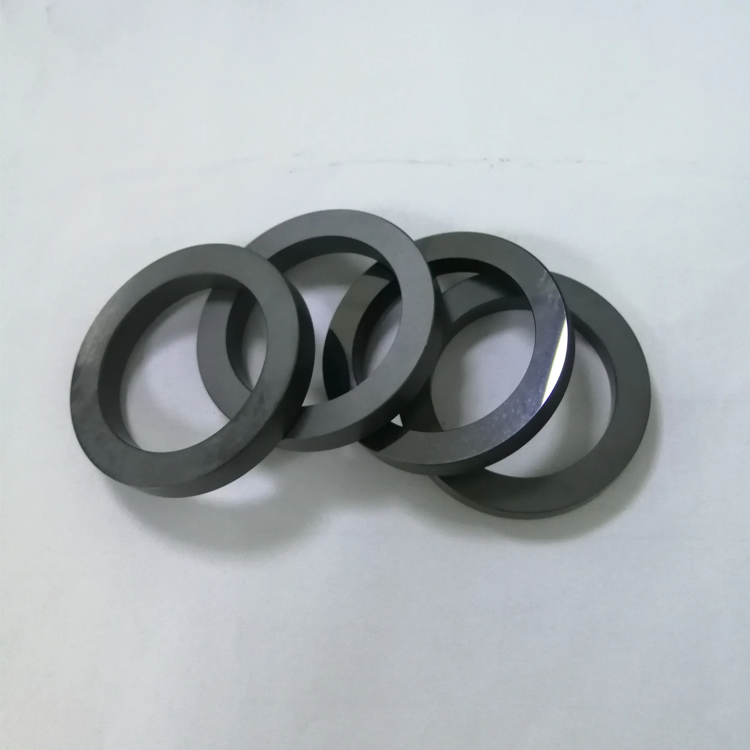
We are specialized in sintered reaction bonded silicon carbide (RB SIC) and pressureless sintering silicon carbide(SSIC) mechanical part, the material is alpha sintered silicon carbide.
Lepuseal was founded in 1998, located in Guangzhou, China. We focus on manufacturing mechanical seal and seal spare parts in the past 20 years. now lepuseal is one of the leading mechanical seal manufacturer in china, and maybe the best cartridge mechanical seal manufacturer in south of china.
Lepuseal have more than 20 years experience in manufacturing mechanical seal, we established a strong technology team include 20+ engineer R&D team, more than 150 skilled workers team, more than 10 person quality control team, that help us to provide strong technology support to our users.
Lepuseal have more than 10000 square meters workshop and 60+ advanced CNC machine to provide strong ability for production. And make sure we can offer fast delivery service to our clients.

1. Lepu double mechanical seal arrangement is made by adopting international advanced technologies. Same quality as the original cost less than the original
2. The popularity of double mechanical seal arrangement also can not be achieved without the contribution of service team. Lepu mechanical seals create excellent quality
Back to back: Two rotating seal rings are arranged facing away from each other. The lubricating film is generated by the barrier fluid. This arrangement is commonly found in the chemical industry. In case of leakage, the barrier liquid penetrates the product.
Face to face:The spring loaded rotary seal faces are arranged face to face and slide from the opposite direction to one or two stationary seal parts. This is a popular choice for the food industry, particularly for products which tend to stick. In case of leakage, the barrier liquid penetrates the product. If the product is considered “hot”, the barrier liquid acts as a cooling agent for the mechanical seal.
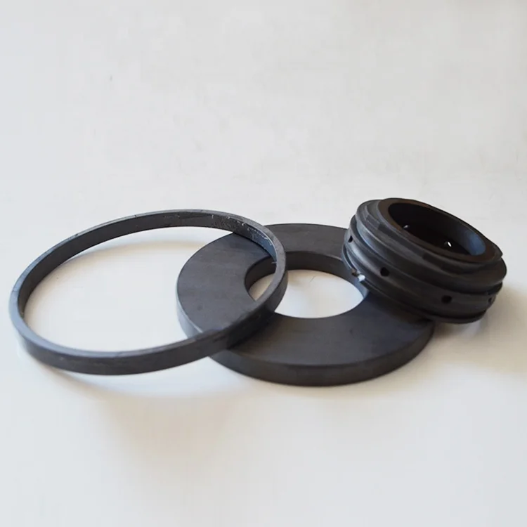
Users can choose different material for this double mechanical seal 208, matching for different liquid conditoncarbon, silicon, and tungsten carbide for this mechanical seal as seal face, if for high temerperature, we suggest to choose rubber seal viton for the rubber parts.
Lepu seal make this dual mechanical seal for many years, and offer professional suggestion when client need this grundfos seal, so we are your reliable specialist for grundfos mechanical seal.
Double mechanical seals are commonly used in the following circumstances:If the fluid and its vapors are hazardous to the operator or environment, and MUST be contained
Guangzhou Lepu machinery CO., LTD becomes one of the leading mechanical seal supplier in south of china, we focus in designing and manufacturing mechanical seal for many kinds of famous brand pumps, our mechanical seal cover many kinds of industry like food, petrol chemical, paper making, sea ship, and so on.

Materials used for the manufacture of mechanical seal faces. These materials must meet the tribological demands unique to mechanical seals. Industry has evolved primarily to the use of mechanical carbons and ceramics for these components. A mechanical seal (Fig. 1) is by its very nature a collection of components that are designed to control leakage of a fluid through a sealing interface. These components serve a wide variety of functions and correspondingly require a wide range of material properties. Many of these properties, such as mechanical strength, thermal conductivity, or corrosion resistance, are similar to considerations made for many other devices. Some properties, however, are unique to mechanical seals, such as coefficient of...
M.B. Huebner, Material selection for mechanical seals, in Proceedings of the 21st International Pump User’s Symposium, Turbomachinery Laboratory, Texas A&M University, College Station, Texas (2005)
Editors and AffiliationsDepartment of Mechanical Engineering and Center for Surface Engineering and Tribology, Northwestern University, Evanston, IL, USA
Machine lapping is the production method of lapping Mechanical Seal Faces. Kemet Lapping Systems are used in both manufacturing and reconditioning processes. The following techniques are applicable to Bench Mounted and Free Standing Machines, as well as Kemet Hand Lapping Systems.
The machine size to be used would normally be determined by the largest seal to be lapped. For example, a Kemet 15 machine could lap seals up to approximately 125mm diameter (5”), whereas a Kemet 24 machine would be required if seals up to 200mm (8”) diameter were to be lapped. In most cases, if the following procedures are adopted, it should be possible to produce high quality reflective surfaces flat to less than 2LB.(0.0006mm)
Many materials used for the manufacture of mechanical seals are now too hard to be lapped using old fashioned conventional abrasives like aluminium oxide and silicon carbide. A Kemet composite lapping plate with a diamond slurry will generate a good cutting rate, and a highly reflective surface finish meaning a secondary polishing stage is not needed.
Kemet Flat Lapping Systems are available to fit most Lapping Machines up to 72” diameter, but for the majority of seal repair workshops 15” or 24” machines are adequate.
Flat Mechanical Seals can only be produced on flat lapping plates. It is therefore essential to regularly check plate flatness. This is the most important skill to master when operating a flat lapping machine.
Seals can then be lapped by placing them inside the machine’s control rings and applying a pressure. If multiple parts are to be lapped inside the same conditioning ring, it is essential that they are the same thickness (+/- 0.5mm). To keep the parts in position during lapping either a work-holder, (sometimes called a nest), should be manufactured. This is typically a 3mm disc of Tufnell with the profile of the parts to be lapped machined into it. Alternatively the pressure weights themselves can be faced with a Kemet Facing Kit. This special material has non-skid properties that hold the parts in position during lapping without the need for a work-holder.
Single seals may be allowed to run freely inside a control ring, but it is important to apply a weight to obtain optimum stock removal. This weight should be balanced. An ideal weight is a large steel ball that can simply be placed on top of the seal. It is also recommended that a rubber band be placed around single seals as this gives them drive within the control rings, thus avoiding tracking on the lapping plate. .
If a large seal is to be lapped on a relatively small lapping machine, then it is possible to remove a control ring and substitute the seal, which will then run in the Roller Yoke Assembly.
Parts were lapped for 10 minutes on the diamond lapping machine and then lapped by hand on the Kemet Copper plate until they were polished. Hand lapping took up to 30 seconds. As the parts were spring loaded the parts had to be put on top of an optical flat to get a light band reading. rather than putting an optical flat on top of the seal.

The present invention relates to a mechanical seal used as a sealing device for a rotating shaft in a pump, a refrigerator, or the like, more particularly to a sliding part (ring) of a mechanical seal which is made of a silicon carbide sintered body.
Materials used for sliding parts (e.g., a stationary ring or rotary ring) of mechanical seals include carbon materials such as bonded carbon bodies and resin-impregnated carbon bodies, cemented carbide bodies, silicon carbide sintered bodies, alumina sintered bodies, and silicon nitride sintered bodies. Increased use is being made of combinations of silicon carbide sintered body parts with other carbon material parts or with other silicon carbide sintered body parts, because silicon carbide sintered parts enable use at a higher PV limiting value (product of pressure applied to sliding surface and circumferential speed of rotary part). A high PV limit enables an increased performance and miniaturization of the sealing device and the apparatus using same. Further, combinations of two silicon carbide sliding parts are frequently used where there is a problem in particle wear due to handling of the slurry.
Silicon carbide sintered bodies have a high hardness, high wear resistance, and a crystal structure with few vitreous grain boundaries. Although silicon carbide sintered bodies are not self-lubricating as are carbon and hexagonal system boron nitride, silicon carbide sintered bodies have a superior smoothness, and therefore, have a small friction coefficient when sliding.
However, when a mirror surface of a silicon carbide sliding part comes into contact with a mirror surface of another silicon carbide sliding part, problems such as abnormal noise (squeaking) and linking at the startup (initial) period easily occur. To solve these problems, an improvement of the dimensional accuracy of the parts, the accuracy of the device and the accuracy of mounting have been proposed. Hard material contacts, however, have a poor familiarity, and thus the problems have not been solved.
When a mirror surface of a silicon carbide sliding part comes into contact with another carbon material sliding part having a self-lubricity, no abnormal noise and linking occur, but carbon blisters appear. This phenomenon starts with a generation of blisters on the sliding surface of the carbon material part, advances to formation of microcracks, and finishes with worm defects (e.g., chipping). Since the defects cause liquid leakage (spill), carbon blisters are a serious defect in mechanical seals. Carbon blisters occur in combinations of carbon material parts and parts of other materials including silicon carbide. It is considered that the frictional heat generated at the startup period causes an alternate expansion and contraction of the carbon material part surface, and that this causes fatigue, and simultaneously, thermal stress failure at the surface. Other factors behind carbon blisters are considered to be (a) thermal decomposition of the impregnating oil in the carbon material part and (b) the explosive reaction of oil held in pores of the carbon material part caused by the frictional heat. Combinations of carbon material sliding parts and other silicon carbide sliding parts are often used in applications involving a high sliding surface pressure. In such cases, the problem of carbon blisters due to the frictional heat at the starting period becomes particularly serious.
The following measures have been proposed to deal with the problem of blisters: (a) increase of strength of the carbon material; (b) improvement of mounting accuracy of two sliding rings to bring them into contact more uniformly; (c) adoption of a double seal; (d) flushing by a low viscosity fluid; and (e) steam heating to raise the sliding surface temperature and lower the viscosity of the sealed liquid. These measures, however, are not sufficient.
In any case, the true solution to the problems is to lower the frictional heat at the start up period, and to lower the frictional heat, it has been proposed to use a reaction-sintered silicon carbide including residual metallic silicon, and to impregnate pores of a porous silicon carbide sintered body with a solid lubricant, as disclosed in Japanese Unexamined Patent Publication (Kokai) Nos. 62-148384, 62-270481, and 63-79775.
Furthermore, a silicon nitride sintered body (ring) for a mechanical seal free from abnormal noise (squeaking) is proposed in Japanese Unexamined Patent Publication No. 62-176970. In this case, one of a pair of sliding parts (rings) is made of a silicon nitride sintered body having either a porosity of from 8% to less than 13% and an average pore diameter of from 50 to 500 μm or a porosity of 13% or more and an average pore diameter of from 25 to 500 μm.
A silicon carbide sintered body produced by the reaction sintering method and containing metallic silicon has less drag and abnormal noise than a silicon carbide sintered body produced by a pressureless (atmospheric pressure) sintering method. The former silicon carbide sintered body, however, has an inferior corrosion resistance, and cannot be widely used. Also, to impregnate a porous silicon carbide sintered body with solid or liquid lubricant such as molybdenum disulfide, graphite, boron nitride, or fluorocarbon oil, it is necessary to repeat vacuum impregnation several times, which raises the production cost. Small pores having a pore diameter of less than 50 μm cannot be impregnated within a short time, whereas large pores having a pore diameter of 50 μm or more lower the strength and wear resistance of the sintered body.
An object of the present invention is to provide a silicon carbide sintered body for a mechanical seal which has a high wear resistance and corrosion resistance, maintains its strength without lowering, and prevents linking, drag, abnormal noise, seizing, and blistering.
Another object of the present invention is to provide a mechanical seal in which damage (e.g., wear) to a pair of sliding parts (rings) of a silicon carbide sintered body part and a part of a soft material such as a bonded carbon body or resin-impregnated carbon body or of a hard material such as a silicon carbide sintered body, alumina sintered body, or cemented carbide body, is prevented as much as possible, and in which liquid spillage is prevented.
The present inventor prepared many silicon carbide sintered bodies having pores by using various techniques and investigated the pore characteristics required for preventing drag, abnormal noise, and blistering of the carbon material when the pores are utilized as oil reservoirs.
The above and other objects of the present invention are attained by providing a silicon carbide sintered body for a mechanical seal which has independent pores having an average pore diameter of from 10 to 40 μm and has a porosity of from 4 to 13 vol %.
The mechanical seal includes a pair of a stationary sliding ring and a rotary sliding ring. At least one of the rings is made of the above-mentioned silicon carbide sintered body. The other ring can be made of a material selected from the group consisting of carbon materials including bonded carbon bodies and resin-impregnated carbon bodies, high-density silicon carbide sintered bodies, cast iron, alumina sintered bodies, and cemented carbide bodies.
The pores must effectively serve as liquid reservoirs, and must have a minimum diameter for easily extruding liquid impregnated therein upon frictional heat at startup, to form a liquid film, and a maximum diameter for maintaining the effect of the liquid reservoirs without runout in a short time and for preventing abnormal wear of the other sliding ring. Therefore, preferably the pores have an average diameter of from 10 to 40 μm, more preferably from 10 to 30 μm. In the case of an average pore diameter of less than 10 μm, the liquid in the pores does not appear on the surface of the sintered body in a short time at startup. In the case of an average pore diameter of more than 40 μm, leakage occurs in the mechanical seal, and the other carbon material sliding ring is considerably worn. When the average pore diameter exceeds 30 μm, the strength of the silicon carbide sintered body is slightly lowered, which causes micro-chipping. Furthermore, in the case of the other carbon material sliding ring, an increased friction coefficient and acceleration of wear may occur.
A cross-section of the silicon carbide sintered body was observed with a scanning electron microscope to measure the diameter of the pores. The average pore diameter was that obtained on the basis of the measured values.
The high-density silicon carbide sintered body usually contains pores having a diameter of 2 μm or less at a porosity of 3 vol % or less at the grain boundaries. Such pores do not give effects similar to those attained in accordance with the present invention.
Bodies having a 5 vol % porosity provide a greater improvement than bodies having a 4 vol % porosity. Where the porosity exceeds 10 vol %, when the other material sliding ring is a silicon carbide sintered sliding ring, micro-chipping occurs.
In general, the porosity of a sintered body is a volume percentage of the sum of open pores and closed (independent) pores to the volume of the sintered body and is obtained by calculation on basis of the sintered density and true density. The pores in the silicon carbide sintered body according to the present invention are almost all independent from each other.
Therefore, the most suitable ranges of the average pore diameter and porosity of the silicon nitride sintered body disclosed in the above-mentioned Japanese Unexamined Patent Publication No. 62-176970 are different from the silicon carbide sintered body according to the present invention.
Regarding the pore shape, the pore must be rounded to avoid stress concentration in a hard material of a silicon carbide sintered body. "Rounded" means that the pore does not have an edge serving as a stress concentrator and has a smooth curved surface.
The methods of forming pores in a silicon carbide sintered body may be roughly classified into two groups: (a) adding a spherical organic material (a large number of organic globulites) to a mixture of sintering raw materials, and calcining the mass to form pores by decomposition and sublimation and (b) inhibiting the densification of a silicon carbide sintered body by changing the sintering conditions to retain pores. In the latter case, for example, there are parameters such as an addition of coarse grains (powder) of a sintering raw material, reduction of sintering aids, raising or lowering of the temperature elevation rate to the sintering temperature, lowering of maximum soaking temperature, and shortening of the maximum soaking time. In this case, the formed pores are generally less rounded and are apt to intercommunicate. Since the former case can easily make the pores more rounded than the latter, it is preferable to use the former process.
The production process for producing a sliding ring of silicon carbide sintered body commonly includes the steps of mixing raw materials (powders) in a ball-mill using water; granulating the mixture by a spray drying method; and compacting the granules into a ring shape with a cold isotactic press or a mold press. Taking the production process into consideration, the organic material to be added should be one which does not dissolve in water and has a suitable heat resistance i.e., will not soften or become fluid at the spray drying step. Preferably, the spherical organic material is made of a synthetic or natural polymer, and may be polystyrene beads made by emulsion polymerization, starch globulites, or pulp globulites.
α-type silicon carbide (α-SiC) powder having an average grain diameter of 0.45 μm was prepared, and polystyrene beads having grain diameters shown in Table 1 were prepared. Then 100 parts by weight of the α-Sic powder, 0.8 part by weight of boron carbide (B4 C) powder, 2.5 parts by weight of carbon black powder, 2.5 parts by weight of polyvinyl alcohol (PVA), and the amounts of polystyrene beads shown in Table 1 were mixed to form mixture samples 1 to 10. Water was added to each mixture to form a slurry having a 40% concentration, and the slurry was stirred in a ball mill for 10 hours and then granulated with a spray dryer.
The obtained granules were loaded in a mold and molded at a pressure of 1.5 ton/cm2 to form a green compact. The green compact was sintered at 2050° C. under an argon atmosphere to obtain test piece samples 1 to 10, respectively, of a silicon carbide sintered body as shown in Table 1.
The obtained test piece samples had the properties shown in Table 1. The bulk specific gravity was measured by a water-displacement method, and the average pore diameter was measured by using a scanning electron microscope. The porosity was obtained by calculation on the basis of the theoretical density of silicon carbide of 3.21 g/cm3. The flexural strength was obtained by a method of testing flexural strength of high performance ceramics (JIS R1601-1981), in which a load is applied at a crosshead speed of 0.5 mm/min at the loading points on the test piece, and the maximum load until the test piece breaks is measured.
As shown in FIG. 1, each of the test piece samples 1 to 10 of the silicon carbide sintered body was set in a wet system friction coefficient measuring device as an upper sample 1. The measuring device included a stationary shaft 2, a rotary shaft 3, and a water bath 5. The stationary shaft 2 was provided with a torque detector 6, was loaded with a spring (not shown), and gripped the upper sample 1 at the bottom thereof. The rotary shaft 3 was driven by a motor (not shown) and gripped a lower sample 7 having the same dimensions as the upper sample 1 at the top thereof. The water bath 5 was filled with water and surrounded the upper and lower samples.
On a pump type testing device for a mechanical seal, a furan resin-impregnated carbon ring was set as a stationary sliding ring and one of the test piece samples 1, 7, and 10 was set as a rotary sliding ring. The testing device (pump) having a rotary shaft 40 mm in diameter was intermittently operated, to circulate C-heavy oil at a pressure of 10 kg/cm and a rotating speed N of 3000 rpm for 15 minutes, and then stopped for 5 minutes to observe the generation of blisters on the carbon ring. In this case, the resin-impregnated carbon ring had an outside diameter of 60 mm and an inside diameter of 41 mm.
When the mechanical seal was used for viscous liquids, an intermittent operation with frequent stoppages, and a high PV value, blistering of the carbon ring usually occurred within a relatively short period. However, when the test piece sample 1 (silicon carbide sintered body), according to the present invention was used in a mechanical seal operating under the above-mentioned conditions, blistering did not occur even after 100 hours of operation (300 interruptions). At this time, the liquid spill of the mechanical seal was 0.5 cc/hr. The sliding surface of the carbon ring had a dull gloss.
In the case of the mechanical seal using the test piece sample 7 (high-density silicon carbide sintered body) according to the comparative example, leakage occurred after 5 hours of operation (15 interruptions). The mechanical seal was then dismantled to check the carbon rotary ring, and five blisters were found on the sliding surface of the carbon ring.
In the case of a mechanical seal using the test piece sample 10 (having a large average pore diameter) according to the comparative example, after 100 hours of operation, the liquid spill of the mechanical seal was 4 cc/hr. The sliding surface of the carbon rotary ring had no luster and was very worn.
As mentioned above, the use of the sliding ring of the silicon carbide sintered body according to the present invention has the advantages of a prevention of blister generation and a reduction of wear in the carbon material sliding ring, as well as a prevention of linking, chipping, abnormal noise, drag, and seizing.
As shown in FIG. 2, the silicon carbide sintered body is used in a mechanical seal. The mechanical seal of FIG. 2 includes a set screw 1, a spring 2, a drive pin 3, a coup ring 4, shaft packings 5, a seal ring 6, insert packings 7, and an insert 8. The seal ring 6 is the silicon carbide sintered body of the present invention.


 8613371530291