
api mechanical seal plans pdf in stock
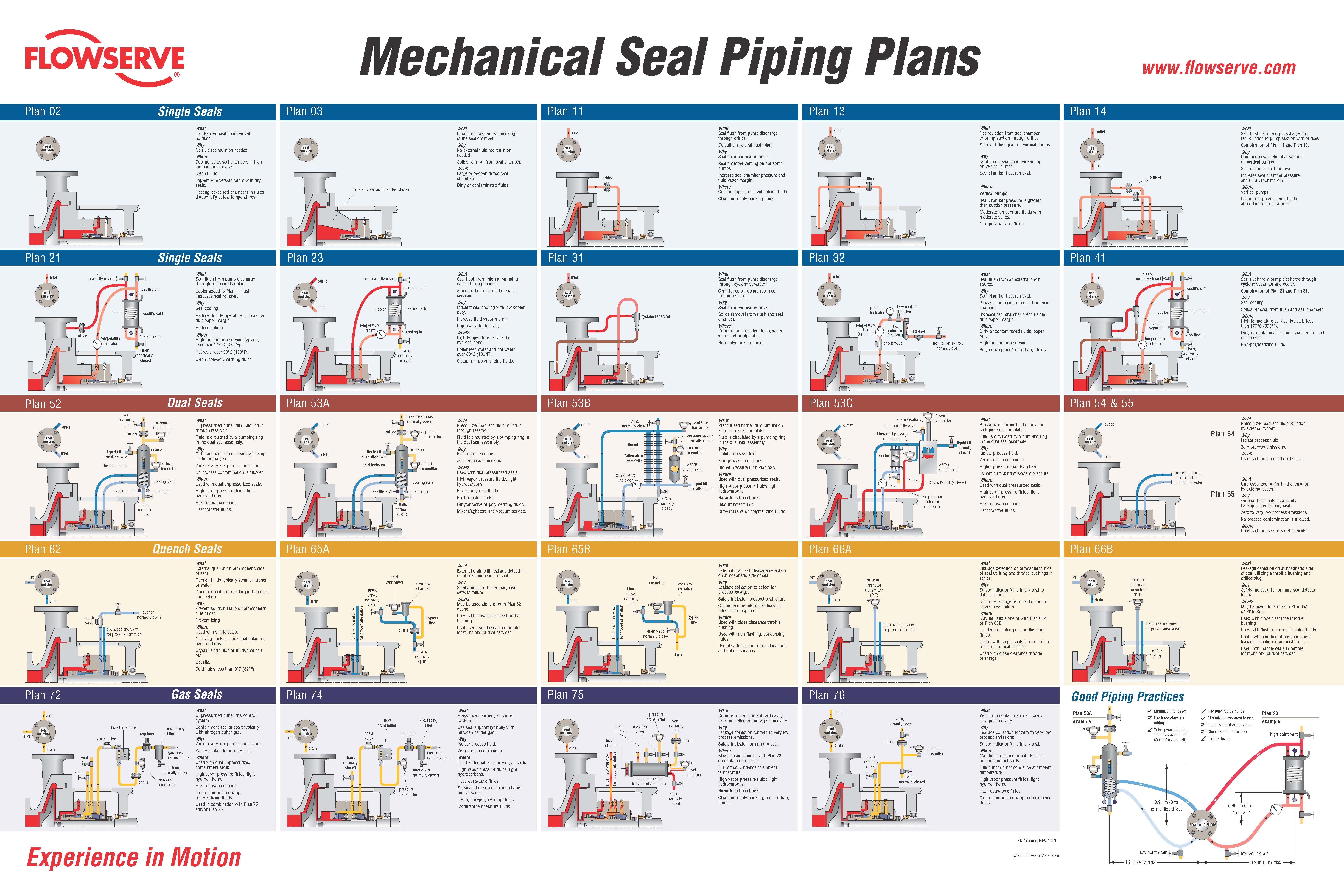
Single Seals plans 01, 02, 03, 11, 13, 14, 21, 23, 31, 32, 41 Dual Seals plans 52, 53A, 53B, 53C, 54, 55 Quench Seals plans 62, 65A, 65B, 66A, 66B Gas Seals plans 72, 74, 75, 76 Mechanical Seal Piping Plans
Flowserve recognizes that one of the most effective ways to achieve long,uninterrupted mechanical seal life is to create a healthy environment aroundthe seal faces. Piping plans help keep mechanical seals running cool andclean, promote safe handling of dangerous fluids, and extend the operationalavailability of rotating equipment. This reference book provides a concisesummary of the most essential piping plans used successfully in today’sprocess plants.
Each plan shows all the standard and optional auxiliary components referencedin API Standard 682 and recommended by Flowserve. Consult your localFlowserve sales engineer to identify the right solution that satisfies yourapplication requirements.Page Layout
Seal End View Piping Plan Layout What, Why, and Where• Viewed from drive end • Illustrated schematic • Describes piping plans, • Shows preferred gland of auxiliary components their purpose, and connection orientation typical applications
What pressure source, Pressurized barrier fluid circulation through reservoir. normally open Fluid is circulated by a pumping ring in the dual seal assembly. outlet pressure Why seal transmitter Isolate process fluid. Zero process emissions. Plan 53A
Plan 53A liquid fill, reservoir Where inlet normally closed Used with dual pressurized seals (”double”). High vapor pressure fluids, light hydrocarbons. level indicator Hazardous/toxic fluids. level transmitter Heat transfer fluids. Dirty/abrasive or polymerizing fluids. cooling coils Mixers/agitators and vacuum service. cooling out cooling in Preventative Maintenance - Reference Appendix B Piping loop must self-vent to reservoir locate at highest elevation. drain, Pressurize reservoir at all times, maximum gas charge 10 - 14 bar (150 - 200 psi). normally Barrier fluid must be compatible with process. closed Reservoir level gage indicates both inboard and outboard seal leakage.
Pump Cross-section Mechanical Seal Preventative Maintenance• Simplified centrifugal • Shows typical seal • Provides general tips to pump shown for all plans arrangements improve reliability and for troubleshooting seal end viewPlan 01
WhatInternal seal chamber flush from pump discharge.Operates similar to Plan 11.WhySeal chamber heat removal.Seal chamber venting on horizontal pumps.
Plan 01Reduce risk of freezing/polymerizing fluid in exposed Plan 11 piping.WhereCustom seal chamber, most likely an ANSI/ASME pump.Clean, moderate temperature fluids.Used with single seals, rarely with dual seals.Preventative MaintenanceFlush typically can not be directed over seal faces and seal heat removal is limited.Calculate flush flow rate based on head loss through internal porting. seal end viewPlan 02 flowserve.com
Plan 02Cooling jacket seal chambers in high temperature services.Clean fluids.Top-entry mixers/agitators with dry seals.Heating jacket seal chambers in fluids that solidify at low temperatures.Preventative MaintenanceProcess must have adequate boiling point margin to avoid vaporization.Cooling fluid in seal chamber jacket may be needed at all times in hot services.Horizontal equipment must be self-venting.Often used in combination with steam quench, Plan 62. seal end viewPlan 03
Plan 03WhereLarge bore/open throat seal chambers.Dirty or contaminated fluids.Preventative MaintenanceProper seal chamber design helps prevent solids from collecting at the seal faces. inlet
Plan 11Seal chamber venting on horizontal pumps.Increase seal chamber pressure and fluid vapor margin.WhereGeneral applications with clean fluids.Clean, non-polymerizing fluids.Preventative MaintenanceUse an orifice with a minimum 3 mm (1/8 inch) diameter.Calculate flow rates to size orifice for adequate seal chamber flow.Increase boiling point margin with proper orifice and throat bushing sizing.Flush should be directed over seal faces with piping at 12 O’clock position.Typical failure mode is a clogged orifice - check temperatures at pipe ends. outlet
WhatRecirculation from seal chamber to pump suction through orifice.Standard flush plan on vertical pumps.WhyContinuous seal chamber venting on vertical pumps.Seal chamber heat removal.
Plan 13WhereVertical pumps.Seal chamber pressure is greater than suction pressure.Moderate temperature fluids with moderate solids.Non-polymerizing fluids.Preventative MaintenanceVent piping loop prior to starting vertical pumps.Use an orifice with a minimum 3 mm (1/8 inch) diameter.Calculate flow rates to size orifice for adequate seal chamber flow.Reduce seal chamber pressure with proper orifice and throat bushing sizing.Typical failure mode is a clogged orifice - check temperatures at pipe ends. outlet
WhatSeal flush from pump discharge and recirculation to pump suction with orifices.Combination of Plan 11 and Plan 13.WhyContinuous seal chamber venting on vertical pumps.Seal chamber heat removal.
Plan 14Increase seal chamber pressure and fluid vapor margin.WhereVertical pumps.Clean, non-polymerizing fluids at moderate temperatures.Preventative MaintenanceUse an orifice with a minimum 3 mm (1/8 inch) diameter.Calculate flow rates to size orifice for adequate seal chamber flow.Increase boiling point margin with proper orifice and throat bushing sizing.Flush should be directed over seal faces.Vent piping loop prior to starting vertical pumps.Typical failure mode is a clogged orifice - check temperatures at pipe ends. vents, normally closed inlet
WhatSeal flush from pump discharge through orifice and cooler.Cooler added to Plan 11 flush increases heat removal.WhySeal cooling.Reduce fluid temperature to increase fluid vapor margin.
Plan 21Reduce coking.WhereHigh temperature service, typically less than 177°C (350°F).Hot water over 80°C (180°F).Clean, non-polymerizing fluids.Preventative MaintenanceSeal cooler and piping must have air vents at highest elevation - vent before starting.When using 682 Seal Cooler, pipe with series flow to maximize heat transfer.Use an orifice with a minimum 3 mm (1/8 inch) diameter.Calculate flow rates to size orifice for adequate seal chamber flow.Increase boiling point margin with proper orifice and throat bushing sizing.Regularly monitor cooler inlet and outlet temperatures for signs of clogging or fouling. vent, normally closed
WhatSeal flush from internal pumping device through cooler.Standard flush plan in hot water services.WhyEfficient seal cooling with low cooler duty.Increase fluid vapor margin.
Plan 23Improve water lubricity.WhereHigh temperature service, hot hydrocarbons.Boiler feed water and hot water over 80°C (180°F).Clean, non-polymerizing fluids.Preventative Maintenance - Reference Appendix ASeal cooler and piping must have air vents at highest elevation - vent before starting.When using 682 Seal Cooler, pipe with parallel flow to minimize head loss.Seal chamber requires close clearance throat bushing to isolate process fluid.Tangential seal gland taps should enter at bottom and exit at top.Regularly monitor cooler inlet and outlet temperatures for signs of clogging or fouling.Process fluids with iron should flow through magnetic separator before cooler. inlet
WhatSeal flush from pump discharge through cyclone separator.Centrifuged solids are returned to pump suction.WhySeal chamber heat removal.Solids removal from flush and seal chamber.
Plan 31WhereDirty or contaminated fluids, water with sand or pipe slag.Non-polymerizing fluids.Preventative MaintenanceCyclone separator works best on solids with a specific gravity twice the process fluid.Seal chamber pressure must be nearly equal to suction pressure for proper flows.Piping should not include an orifice and is not expected to vent the seal chamber.Typical failure mode is clogged separator or pipes - check temperatures at pipe ends. inlet
WhatSeal flush from an external clean source.WhySeal chamber heat removal.Process and solids removal from seal chamber.Increase seal chamber pressure and fluid vapor margin.
WhatSeal flush from pump discharge through cyclone separator and cooler.Combination of Plan 21 and Plan 31.WhySeal cooling.Solids removal from flush and seal chamber.
Plan 41WhereHigh temperature service, typically less than 177°C (350°F).Dirty or contaminated fluids, water with sand or pipe slag.Non-polymerizing fluids.Preventative MaintenanceSeal cooler and piping must have air vents at highest elevation - vent before starting.When using 682 Seal Cooler, pipe with series flow to maximize heat transfer.Cyclone separator works best on solids with a specific gravity twice the process fluid.Seal chamber pressure must be nearly equal to suction pressure for proper flows.Typical failure mode is clogged separator or pipes - check temperatures at pipe ends. vent, normally open pressure outlet transmitter orifice seal end view inlet reservoirPlan 52
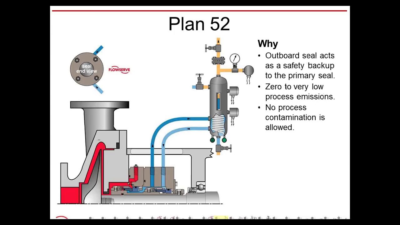
WhatUnpressurized buffer fluid circulation through reservoir.Fluid is circulated by a pumping ring in the dual seal assembly.WhyOutboard seal acts as a safety backup to the primary seal.Zero to very low process emissions.
Plan 52No process contamination is allowed.WhereUsed with dual unpressurized seals.High vapor pressure fluids, light hydrocarbons.Hazardous/toxic fluids.Heat transfer fluids.Preventative Maintenance - Reference Appendix BPiping loop must self-vent to vapor recovery/flare system near atmospheric pressure.Process vapor pressure is generally greater than reservoir pressure.Buffer fluid must be compatible with process leakage.Primary seal leakage is indicated by increased vent pressure.Reservoir level indicator shows outboard seal leakage. pressure source, normally open
outlet orifice pressure seal transmitter end view reservoirPlan 53A
WhatPressurized barrier fluid circulation through reservoir.Fluid is circulated by a pumping ring in the dual seal assembly.WhyIsolate process fluid.Zero process emissions.
Plan 53AWhereUsed with dual pressurized seals.High vapor pressure fluids, light hydrocarbons.Hazardous/toxic fluids.Heat transfer fluids.Dirty/abrasive or polymerizing fluids.Mixers/agitators and vacuum service.Preventative Maintenance - Reference Appendix BPiping loop must self-vent to reservoir located at highest elevation.Pressurize reservoir at all times, maximum gas charge 10 - 14 bar (150 - 200 psi).Barrier fluid must be compatible with process.Reservoir level indicator shows both inboard and outboard seal leakage. vent, normally closed pressure outlet transmitter seal pressure source, end view finned pipe normally closedPlan 53B
WhatPressurized barrier fluid circulation with bladder accumulator.Fluid is circulated by a pumping ring in the dual seal assembly.WhyIsolate process fluid.Zero process emissions.
Plan 53BHigher pressure than Plan 53A.WhereUsed with dual pressurized seals.High vapor pressure fluids, light hydrocarbons.Hazardous/toxic fluids.Heat transfer fluids.Dirty/abrasive or polymerizing fluids.Preventative Maintenance - Reference Appendix BPiping loop must be fully vented before starting.Accumulator must be pressurized at all times, usually by gas charge.Barrier fluid must be compatible with process.Regularly monitor barrier pressure - manually add barrier fluid when pressure decays. level indicator level transmitter
outlet vent, normally closed differential pressure seal transmitter liquid fill, end view normallyPlan 53C
WhatPressurized barrier fluid circulation with piston accumulator.Fluid is circulated by a pumping ring in the dual seal assembly.WhyIsolate process fluid.Zero process emissions.
Plan 53CHigher pressure than Plan 53A.Dynamic tracking of system pressure.WhereUsed with dual pressurized seals.High vapor pressure fluids, light hydrocarbons.Hazardous/toxic fluids.Heat transfer fluids.Preventative Maintenance - Reference Appendix BPiping loop must be fully vented before starting.Reference line must tolerate process contamination without plugging.Barrier fluid must be compatible with process.Reservoir level indicator indicates both inboard and outboard seal leakage. outlet
Plan 54WhereUsed with pressurized dual seals.High vapor pressure fluids, light hydrocarbons.Hazardous/toxic fluids.Heat transfer fluids.Dirty/abrasive or polymerizing fluids.Mixers/agitators.Preventative MaintenancePiping loop must be fully vented before starting.Circulating system must be pressurized and energized at all times.Barrier fluid must be compatible with process.Circulating system level indicator shows both inboard and outboard seal leakage. outlet seal end viewPlan 55
WhatUnpressurized buffer fluid circulation by external system.WhyOutboard seal acts as a safety backup to the primary seal.Zero to very low process emissions.No process contamination is allowed.
Plan 55Additional heat removal from the inner seal.Seal cannot induce circulation.WhereUsed with unpressurized dual seals.Hazardous/toxic fluids.Fluids that may solidify in contact with atmosphere.Preventative MaintenancePiping loop must be fully vented before starting .Buffer fluid must be compatible with process leakage.Accumulated process leakage should be routed to a recovery system. inlet seal end viewPlan 62
WhatExternal quench on atmospheric side of seal.Quench fluids typically steam, nitrogen, or water.WhyPrevent solids buildup on atmospheric side of seal.Prevent icing.
Plan 62WhereUsed with single seals.Oxidizing fluids or fluids that coke, hot hydrocarbons.Crystallizing fluids or fluids that salt out.Caustic.Cold fluids less than 0°C (32°F).Preventative MaintenanceQuench inlet should be on top of gland with outlet/drain on bottom.Quench pressure should be limited to 0.2 bar (3 psi) or less.Use throttle bushing on atmospheric side of seal to direct quench flow to seal drain.Monitor regularly, checking for closed valves, blocked lines, and steam trap condition. seal level end view block transmitter valve,Plan 65A
Plan 65AMay be used alone or with Plan 62 quench.Used with close clearance throttle bushing.Useful with single seals in remote locations and critical services.
Preventative MaintenanceDrain must be on bottom of gland with downward-sloped piping.Continuously drain to liquid recovery system.Orifice downstream of level switch transmitter 5 mm (1/4 inch) must be oriented vertically.Bypass line from overflow chamber must re-enter below orifice.Piping may require heat tracing when used with solidifying fluids.Monitor regularly, checking for closed valves, blocked lines, and working level transmitter. seal level end view block transmitter overflowPlan 65B
WhatExternal drain with leakage detection on atmospheric side of seal.WhyLeakage collection to detect for process leakage.Safety indicator to detect seal failure.Continuous monitoring of leakage rates to atmosphere.
Plan 65BWhereUse with close clearance throttle bushing.Use with non-flashing, condensing fluids.Useful with seals in remote locations and critical services.
Preventative MaintenanceDrain must be on bottom of gland with downward sloped piping.Empty collection vessel when level transmitter indicates the vessel is full.Bypass line from collection vessel must re-enter below drain valve.Piping may require heat tracing when used with solidifying fluids.Monitor regularly, checking for closed valves, blocked lines, and working level transmitter. pressure PIT seal indicator end view transmitterPlan 66A
WhatLeakage detection on atmospheric side of seal utilizing two throttle bushings in series.WhySafety indicator for primary seal to detect failure.Minimize leakage from seal gland in case of seal failure.
Plan 66AWhereMay be used alone or with Plan 65A or Plan 65B.Used with flashing or non-flashing fluids.Useful with single seals in remote locations and critical services.Used with close clearance throttle bushings.
Preventative MaintenanceDrain must be on bottom of gland with downward sloped piping.Continuously drain to a liquid recovery system.Monitor for high pressure. pressure PIT seal indicator end view transmitterPlan 66B
Plan 66BMay be used alone or with Plan 65A or Plan 65B.Used with close clearance throttle bushing.Used with flashing or non-flashing fluids.Useful when adding atmospheric side leakage detection to an existing seal.Useful with single seals in remote locations and critical services.
Preventative MaintenanceDrain must be on bottom of gland with downward sloped piping.Continuously drain to a liquid recovery system.Monitor for high pressure.Check orifice regularly for build up and plugging. vent flow coalescing inlet seal filter check transmitter end view regulator valvePlan 72
WhatUnpressurized buffer gas control system.Containment seal support typically with nitrogen buffer gas.WhyZero to very low process emissions.Safety backup to primary seal.
Plan 72WhereUsed with dual unpressurized containment seals.High vapor pressure fluids, light hydrocarbons.Hazardous/toxic fluids.Clean, non-polymerizing, non-oxidizing fluids.Used in combination with Plan 75 and/or Plan 76.Preventative MaintenanceClean, reliable, low pressure gas must be supplied to seal at all times.Bottled gas supply is not recommended except as part of emergency backup system.Primary seal leakage is indicated by pressure in the vent line.Vent or drain are usually connected to low pressure vapor recovery/flare system. inlet flow coalescing seal transmitter filter end view check regulator valvePlan 74
Plan 74WhereUsed with dual pressurized gas seals.High vapor pressure fluids, light hydrocarbons.Hazardous/toxic fluids.Services that do not tolerate liquid barrier seals.Clean, non-polymerizing fluids.Moderate temperature fluids.Preventative MaintenanceClean, reliable, pressurized gas must be supplied to seal at all times.Barrier pressure is typically at least 1.75 bar (25 psig) above seal chamber pressure.Flow indicator shows both inboard and outboard seal leakage.Bottled gas supply is not recommended except as part of emergency backup system. pressure test transmitter connection isolation level valve vent, seal end view indicator normally open orifice
Drain - see end view level transmitter reservoir located below seal drain port
WhatDrain from containment seal cavity to liquid collector and vapor recovery.WhyLeakage collection for zero to very low process emissions.Safety indicator for primary seal.
Plan 75WhereMay be used alone or with Plan 72 on containment seals.Fluids that condense at ambient temperature.High vapor pressure fluids, light hydrocarbons.Hazardous/toxic fluids.Clean, non-polymerizing, non-oxidizing fluids.Preventative MaintenanceCollection reservoir must be located below seal drain and downward-sloped piping.Continuously vent collection reservoir to low pressure vapor recovery/flare system.Drain collection reservoir to liquid recovery system as needed.Primary seal leakage is indicated by increased vent pressure.Monitor regularly for liquid level, valve settings, and low vent pressure. vent vent, normally open seal end viewPlan 76
WhatVent from containment seal cavity to vapor recovery.WhyLeakage collection for zero to very low process emissions.Safety indicator for primary seal.
Plan 76WhereMay be used alone or with Plan 72 on containment seals.Fluids that do not condense at ambient temperature.High vapor pressure fluids, light hydrocarbons.Hazardous/toxic fluids.Clean, non-polymerizing, non-oxidizing fluids.Preventative MaintenanceContinuously vent to low pressure vapor recovery/flare system.Vent piping should include a condensate drain.Primary seal leakage is indicated by increased vent pressure.Monitor regularly for valve settings, blocked lines, and low vent pressure. Single Seals - Plan 23 shown What Minimize restrictions in piping systems high point vent Why Optimum flow rate for best piping plan performance WhereAppendix A
low point Horizontal drain Equipment 0.9 m (3 ft.) maxGood Piping Practices Dual Seals - Plan 53A shown Minimize line losses Use large diameter tubing Only upward sloping lines (slope shall be 40 mm/m [0.5 in/ft]) Use long radius bends
low point Horizontal drain Equipment 1.2 m (4 ft.) max Airfin Coolers TM Seal Cooler 682 Seal Cooler ReservoirsAccessories
Forced air or natural Compact design Seal cooler for General duty and convection seal coolers dual coil seal cooler complete API 682 API 682 compliant specifications reservoirs
Plans 21, 23 & 41 Plans 21, 23 & 41 Plans 21, 23 & 41 Plans 53, 53A & 53B flowserve.com
AccessoriesAccumulator Control Panel Standalone dual seal Mobile cart to manually Complete control support system fill liquid reservoirs system for dual gas seals
Plan 53C Plan 54 Plans 52 & 53 Plans 72 & 74 Seal Gard I & II Orifice Magnetic Separator Cyclone SeparatorAccessories
Combination flush Plug and plate Iron particle separator Solid particle separator flow regulator and style flush line for seal flush used in dirty flush stream meter orifices
Plan 32 Plans 11, 13, 14, & 21 Plan 23 Plans 31 & 41 flowserve.com
Plan 62 Plan 62 modified Plans 52, 53 & 54NotesNotesNotesNotesFTA160eng REV 1-15 Printed in USA USA and Canada To find your local Flowserve representative Kalamazoo, Michigan USA and find out more about Flowserve Corporation Telephone: 1 269 381 2650 visit www.flowserve.com Telefax: 1 269 382 8726

Swagelok’s standard designs can quickly and easily be configured to meet your specific needs whether single-seal, dual-seal, quench or gas seal. Our plans meet API 682 standards that support the use of tubing instead of piping, reducing potential leak points and providing enhanced vibration resistance.
Watch episode 5 of Swaging with Garyas he interviews Technical Advisor JakeJones, a former millwright, and I&E tech and planner, with one of the largest rubber plants on the Gulf Coast about the benefits of Swagelok"s Seal Support Systems.
Kits adhere to API best practices by showing technicians where to bend tubing to eliminate potential leak points through the reduction of elbow fittings and pipe threads.
In the past there was only one Plan 53, but with the 2nd Edition of API 682 and the 1st Edition of ISO 21049 other variations of Plan 53"s were created.
The major difference in the plans is that Plan 53A uses an external reservoir, while Plans 53B and 53C run within a closed loop system with a make-up system piped to it for replenishment of the barrier fluid.
In dual pressurized sealing arrangements the inner process seal can have its own flush plan; in such applications the complete flush plan system designation should include both plans. For example, Plan 11/53A means that the inner seal has its own flush plan, Plan 11. The API/ISO default is for no separate flush plan when using any of the Plan 53"s, but this can vary with the application conditions.
With the older traditional back-to-back seal arrangement the inboard seal usually does not require a separate flush. In applications such a hydrofluoric acid, where it is both extremely hazardous and corrosive, a Plan 32 can be used in conjunction with a Plan 53. The dual pressurized face-to-back seal arrangement eliminates some of the potential problems associated with the back-to-back design. This face-to-back seal arrangement sometimes incorporates a reverse pressure capability that is not a default with the back-to-back design.
Also, face-to-back arrangements do not have a dead zone underneath the inboard seal that can become clogged by dirty process fluid and lead to seal hang-up. However, the face-to-back arrangement is not a cure-all. With the product on the seal O.D. and with it being used on API pumps that still incorporate throat bushings, it is advantageous to provide a flush for the inboard seal on a number of applications.
Abrasives can accumulate in the more closed API type seal chambers compared to the newer generation chemical duty pumps with large cylindrical bore or tapered bore chambers. The use of a Plan 11 or similar bypass type flush for the inner seal has advantages. It can help keep the seal chamber clean. It also has an improved overall heat transfer setup versus just using a Plan 53 system alone.
In comparison to a Plan 54, Plans 53A/B/C are usually less complex and less expensive. With Plans 53A/B/C, both the inner and the outer seals are lubricated by the barrier fluid, which can be selected for optimum seal performance. Plans 53A/B/C are usually selected for dirty, abrasive, or polymerizing process services which might be difficult to seal directly with single seals or with dual unpressurized seals using a Plan 52. There will always be some leakage of the barrier fluid into the process with any pressurized system.
With some of the Plan 53 systems the volume of barrier fluid is limited, especially compared to a Plan 54 system. Venting of the seal chamber is essential for all Plan 53"s where vapor locking can if vapor bubbles collect near the pumping ring or in the piping.
Plan 53A uses an external reservoir to provide barrier fluid for a pressurized dual seal arrangement. Reservoir pressure is produced by a gas, usually nitrogen, at a pressure greater than the maximum process pressure being sealed. The gas pressure is regulated by a system that is outside the schematic of the piping plan. Circulation of the barrier fluid is maintained by an internal pumping ring.
Like Plan 52 reservoirs, cooling is accomplished internal coil of tubing to remove the heat. Also like Plan 52 reservoirs, the volume of barrier liquid can vary from two gallons to 5+ gallons, where API and ISO standards specify 3-gal and 5-gal, depending upon the shaft diameter.
For non-API specifications, smaller reservoirs - typically 2-gal - are often used, especially at ambient pumping temperatures. Pressure alarms, pressure gages and level switches are typically standard equipment and are required by API 682/ISO 21049.
The usual guideline for Plan 53 barrier pressures is that they be a minimum of 20-psi to 50-psi above the maximum process pressure seen by the seal. Barrier pressure is normally supplied by a plant wide distribution system. Nitrogen bottles should not be used as they require a lot of attention and maintenance.
API 682/ISO 21049 recommends that the system be limited to 150-psig due to gas entrainment into the barrier fluid. Field experience has shown that with the proper barrier fluid, Plan 53A systems can be used up to 300-psig if the temperature is controlled to less than 250-deg F. A variation to this would be to use an accumulator to eliminate gas entrainment.
Installation should be limited to a single seal installation even on between bearing pumps. Therefore for a large number of installations, Plan 53A can be more expensive than Plan 53B or 53C.
Flow in the circulating system is usually induced by an internal pumping device. The make up system can be configured a number of ways based upon the customer"s preference, ranging from a simple hand pump to an elaborate pumping system feeding multiple pumps/seals.
API 682, 3rd edition does not provide guidelines for sizing the accumulator of Plan 53B, but the total fluid volume of the system should be about the same as the volume of a 53A system.
The finite volume of the accumulator requires a designed pressure operating range between refills (in excess of that required for a Plan 53A) and this must be built into the pressure rating of the seals.
Plan 53C is a variation of Plan 53B that uses a piston accumulator to track the pressure of the seal chamber. In Plan 53C, the piston accumulator has a reference line from the seal chamber to the bottom of the accumulator. There are differences in diameter of the internal piston so that a higher pressure is generated on the top half, which in turn is piped to the circuit loop into and out of the seal chamber.
The advantages and disadvantages are the same as the Plan 53B system. Additionally, the disadvantage of this system is that pressure spikes or pressure drops in the process pressure will vary the pressure on the outer seal that may create a temporary leakage condition. Also, tracking pressures can always be subject to delays that can cause a temporary loss of positive pressure differential across the inboard seal.
PHOTO : https://www.eagleburgmann.com/media/literature-competences-products-solutions/division-mechanical-seals/competences/brochure-barrier-buffer-media-for-mechanical-seals
A sealing system, consisting of a mechanical seal and an associated supply system that is balanced by individual applications, is the utmost guarantee for a reliable sealing point and uninterrupted pump service. The performance of the seal is greatly influenced by the environment around the seal faces, making the provision of suitable, clean fluids as well as a moderate temperature an essential topic.
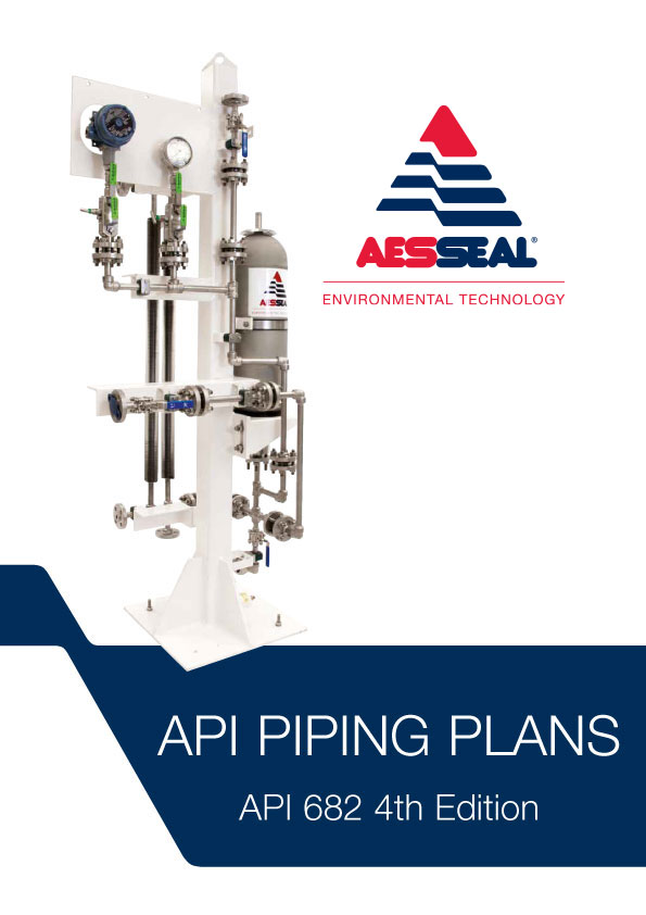
This guiding booklet provides a condensed overview of all piping plans established by the API 682 4th edition guidelines. Each illustrated piping plan is briefly described, and a recommendation that considers the media characteristics in terms of the relevant application and corresponding configurations is given to help you reliably select your sealing system. Furthermore, the content of this booklet has been enriched by providing clues – so-called ‘remarks and checkpoints’ – where EagleBurgmann shares the experiences gained from multiple equipped plants.
Several factors play a major role when choosing the product, the product type, the materials used and how it is operated: process conditions at the sealing location, operating conditions and the medium to be sealed.
No matter what requirements our customers have, EagleBurgmann understands how these factors affect functionality and economic viability, and they translate this expertise into outstanding long-term, reliable sealing solutions. EagleBurgmann has all the expertise needed to manage and support the entire development, life and service cycle of its sealing solutions.
EagleBurgmann offers customers the widest product portfolio of seals and seal supply systems according to API 682 4th edition. The configurations listed for each individual piping plan are to be understood as recommendations including possible utilizations which may also be applied.
EagleBurgmann is one of the internationally leading companies for industrial sealing technology. Their products are used wherever safety and reliability are important: in the oil and gas industry, refining technology, the petrochemical, chemical and pharmaceutical industries, food processing, power, water, mining, pulp & paper and many others. More than 6,000 employees contribute their ideas, solutions and commitment towards ensuring that customers all over the world can rely on their seals and services. More than 21,000 EagleBurgmann API-seals and systems are installed world-wide.


 8613371530291