
goulds pump mechanical seal free sample

Locke Well & Pump Company is an independent dealer and is not affiliated with the manufacturers of the products it sells except where expressly noted otherwise.

Locke Well & Pump Company is an independent dealer and is not affiliated with the manufacturers of the products it sells except where expressly noted otherwise.

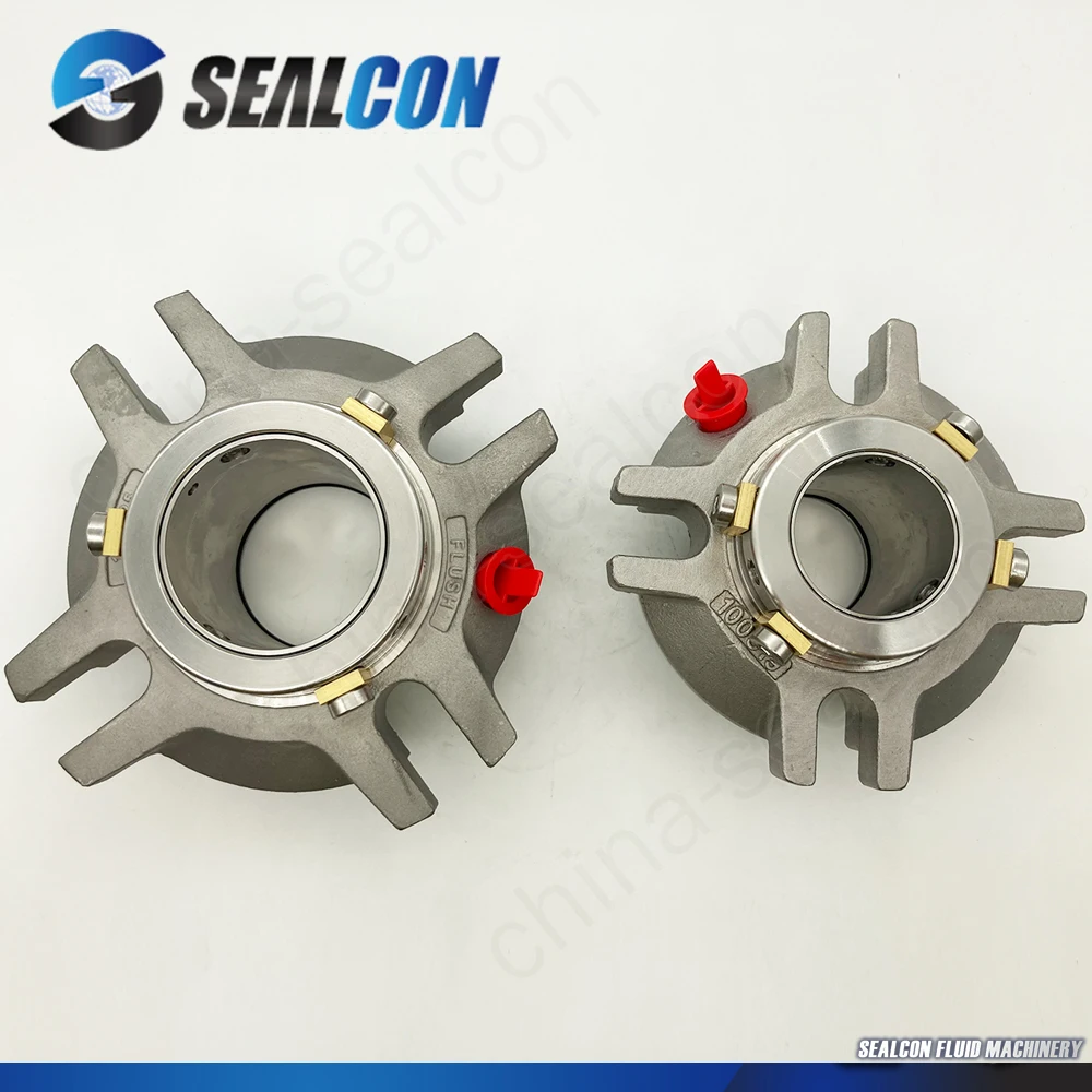
1. Stardard in dustrial 92N mechanical seal for water pump as John crane which is widely used in oil ,water,organic solvent,and other weak corrosive medium.
The mechanical seal is one of the most important components of a pumping system. As the name suggests, the seal is a simple component that forms a barrier between the motor and the volute of a pump, protecting the motor against leakage.
Leakage is death to any mechanical instruments and pumps are no exception. Fluid leakage often results in corrosion of the casings, sleeves and bearings. Corrosion left unattended over a period of time will will degrade the construction material of the pump. Fluid leakage that enters the motor shaft can short circuit the motor.
Naturally, these problems will impede proper pump functioning and eventually could stop the pump from running altogether. Companies often spend a lot in terms of money, wasted manpower and lost operational time to fix leakage.The mechanical seal is designed to prevent that leakage from ever happening. Mechanical seal shaft failure is the number one cause of pump downtime according to WaterWorld magazine.
Submersible wastewater pumps, such as sewage pumps, are particularly susceptible to the dangers of leakage as their operation depends on being surrounded by water that may contain potentially corrosive or clogging waste solids. This water can accumulate in the motor casing and obviously a submersible pump cannot be drained without interrupting operation.
A wide variety of seal types are available for any number of applications. The type of seal most commonly used in sewage pumps is an end face mechanical seal.
In an end-faced seal two ringed “faces” or seal heads rest flat against each other (but are not attached) in the seal chamber, which is located between the volute (the “wet end” of the pump) and the motor. An actuator, such as a spring, presses the faces close to each other.
The rotating motor is inserted through the two ringed faces and attached to the impeller. As the motor shaft rotates, the upper seal (closer to the motor) rotates with the shaft. The bottom seal closer to the volute remains stationary.
This action creates a sealing interface which keeps the water in the volute and prevents leakage. A minimal amount of water might escape the sealing interface but this liquid essentially acts as a lubricant for the seal and will eventually evaporate from heat.
All the components of an end faced mechanical seal work in unison to prevent leakage and are equally important to proper functioning. The main components are:
1. The primary seal faces that rest against each other. The primary seal faces are typically made of durable materials such as silicon carbide, ceramic carbide or tungsten. Certain materials work better for certain applications. For instance, silicon carbide is resistant to acidic liquids, less so to alkaline liquids. Generally, face materials should be of high hardness and should have the ability to slide on each other.
2. Secondary seal surfaces or faces. The secondary faces surround the primary seal faces, but do not rotate. The secondary surfaces hold the primary faces in place and create an additional barrier. Secondary faces can come in a variety of forms – examples include o-rings, elastomers, diaphragms, mating rings, gaskets and wedges. The secondary face also allows for shaft deflection and misalignment.
3. Actuator or a means of pressing the seal faces together and keeping the entire seal properly aligned to the shaft. Often (but not always) a loaded spring. The actuator is mounted above the seal face closer to the motor while the motor shaft passes through the spring.
Mechanical seals are precise, sensitive and temperamental instruments. Even seemingly minor mishandling can negate the seal’s functionality. Therefore Pump Products highly recommends leaving the mounting and installation of mechanical seals to qualified technicians.
Before you actually handle your mechanical seal, be sure to wash your hands thoroughly. Because the faces are meant to be extremely flat, even small particles from the oil of human hands can damage the surface integrity of the faces and render the seal useless. Make sure to wipe the seal itself with an alcohol solution, in case another person touched the seal faces during the packing or shipping process.
The following is a basic guide to replacing a defective mechanical seal. Each seal should come with its own specific instructions, but this is overview covers the most essential parts of the mounting process.
2. Carefully remove the old seal head, taking care not to scratch the motor shaft. Take note of how the seal was mounted; the new seal will be mounted in the same manner.
Mechanical seals are classified by construction type and the construction type is expressed through a letter code. The seal listing code will designate the construction material of each component. For example, here is a construction code guide from U.S. Seal:
The construction materials of the seal will in turn inform what specific seal is suited for your specific pumping application. You can consult a material recommendation chart to best choose the right mechanical seal.
The above chart is a guide to identifying and sizing the appropriate mechanical seal for your pump. Because seals are specifically engineered instruments, making sure that the seal is properly sized for a specific pumping system and application is critical. Manufacturers often make specific recommendations for the type of material to use for an application as well – a recommendation chartis helpful.

The need for a leak-free pump became urgent in the modern age when industrial pumps began handling hazardous liquids. In the case of a toxic or flammable liquid, it is essential to protect both people and the environment from any leaks. Also, every leak means wasted product, which becomes significant when pumping expensive media, such as pharmaceutical materials.
Consider why it is so challenging to prevent pumps from leaking. Take the common centrifugal pump as an example. In this pump, a shaft and impeller are rotated by a motor, but the motor is located outside the pump. It is where the shaft exits the pump, specifically at the points of contact between the rotating and stationary parts, that leaks can and do occur.
The stuffing box is a chamber situated on the outside of the pump case where the shaft exits. Within it, sealing material—a soft packing substance—is laid around the shaft.
Using a special device (a nut in the simplest case), the packing is then compressed, causing it to press against the walls of the chamber and the shaft, thus preventing liquid from flowing out of the pump.
However, the shaft has to be in close contact with the packing material in order for the seal to be tight. This can create friction and lead to a shortened service life.
The main elements of mechanical seals are two rings: a moving one, which rotates with the shaft, and a stationary one, which is attached to the pump body with a pin.
Tightness against leaks is created by contact between the ring surfaces, which forms a so-called friction pair. To provide the contact, the moving ring is pressed against the fixed ring by a spring, spring unit or bellows—which is an elastic single-layer or multilayer corrugated sheath made of metallic, nonmetallic and composite materials. For additional sealing, secondary seals are used, which are O-rings made of elastomer.
Choosing the right seal ring materials is not a trivial task. The rings need to have sufficient strength and wear resistance to withstand the effects of pump operation and be chemically resistant to the pumped medium. In addition, they must be able to withstand the high temperatures that arise due to friction. For these reasons, friction pairs are surprisingly sophisticated technologies, requiring the theoretical and calculation disciplines of mechanics, thermodynamics, hydraulics and tribology. Due to the small clearance between the rings, the manufacture of modern mechanical seals actually falls into the category of nanotechnology.
Single friction pair mechanical seals may only minimize leaks, not eliminate them. To further attempt to eliminate leaks, double mechanical butt seals were created. The auxiliary system—called a flushing plan or piping plan—feeds a special fluid, called a barrier, to the area of the seal between the two rings of the friction pair. Its pressure is held a bit higher than that of the pumped medium in the sealing area and, in this way, tightness is achieved. The barrier fluid also performs the necessary tasks of heat removal and lubrication in the event that the pumped media lacks the properties to do so. Water, for example, loses its lubricating properties at about 176 F (80 C).
Mechanical double butt seals can eliminate leaks of the pumped fluid to atmosphere. However, they can be relatively expensive and difficult to maintain. In addition, even the most carefully constructed friction pair will fail in time due to wear, so they require continuous monitoring and replacement.
The principle of magnetic coupling is based on the transmission of torque from the driver to the impeller of the pump using permanent magnets made of rare earth metals (Image 3). The motor rotates the shaft with the driving magnets attached to it, which are located outside a sealed pump casing. The driven magnets are located inside the pump casing and are attached to the impeller. The movement of the driving magnets causes the driven magnets to rotate.
Due to this remote transmission of power, the shaft does not need to pass through the casing, so there are no holes and there can be no leaks. However, these pumps tend to be more expensive, due to the cost of the state-of-the-art magnets they require. Usually, these are made of exotic alloys of neodymium, cobalt and samarium, but neodymium iron boron (NdFeB) alloy is now considered more effective. The service life of these magnets can be tens, or even hundreds, of years—often longer than the service life of the pump itself.
The other advance that came about from the development of electromechanics and electromagnetic theory was the canned motor pump. This device combines the function of the electric motor with that of the classic centrifugal pump. It is similar to a pump with a magnetic coupling, but the role of the magnets is performed by the windings of the stator (fixed part of the electric motor) and the rotor. It is called “canned” because the motor is protected from short circuits by a special cylinder (shell) and located inside the pump casing in the pumped liquid, which simultaneously lubricates and cools the bearings.
Because canned motor pumps use fewer parts, they are compact. However, because the coils of the stator and the rotor are separated by several partitions, their efficiency can be relatively low. Therefore, these devices are ruggedly useful but do consume more power.
Persistent effort over many years has now produced a variety of options to achieve a leak-free pump. Each has its own mix of advantages and drawbacks. To determine which is best for your operation, specialists will select a design depending on the properties of the pumped liquids, operating conditions and economic constraints.


 8613371530291