
api 610 mechanical seal code quotation
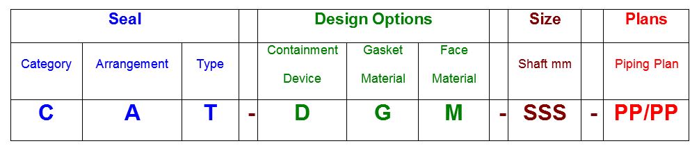
A seal code is an abbreviated method of communicating basic specifications for the mechanical seal. Sadly, the seal code has been changed with every edition of API 682. Fortunately, the new code, described in API 682 4th Edition Annex D, is the best to date and includes some concepts and codes from the historical API 610 seal code. The new code uses eight fields:
API 682 4th Edition was the first edition to include materials in the description and in many ways represents a combination of API 682 coding and the old API 610 codes.
4th Edition coding comprises four sections, some being sub-divided. The table below shows the construction of a typical seal code, it is intended to accurately describe the seal and seal system being implemented in a given application.
T: Seal type A, B or C per API 682 4th Edition definitions. For dual seals using different inner and outer seal types, show both types using the format inner/outer.
Note that the codes used for Design Options are the same as those used in API 610 for materials that are included in both systems. On the other hand, some materials cannot be specified because API 682 does not recommend them. Such materials must be specified with an “X”.
For many years the pump standard API 610 contained a mechanical seal coding system which became widely used in industry. This coding method provided a reference to the nomenclature and features used with mechanical seals that were current during that time period. While this coding method is obsolete it still is still being used in some areas of industry. It is presented herein as a historical reference only.
A very commonly used code was BSTFM which translates to a balanced single seal with throttle bushing in the gland plate. Gaskets would be FKM (fluoroelastomer). Seal faces would be carbon vs nickel bound tungsten carbide.

API (American Petroleum Institute) is a set of standards used to define systems, tests, and equipment design, mainly in the Oil & Gas industry. There are other standards, such as ISO, ASME, NEMA, or ANSI. Although these standards may be referred to alongside API, they are not otherwise related, and although some of these standards overlap, each one is generally focused on a different sector.
API standards include design criteria for a wide range of equipment and components. Power Zone is involved daily with the API standards relating to pumps and pump components, as well as API guidelines for pump testing and API design criteria for pump baseplate design.
Even though there is no overall rule or law that API standards must be adhered to (many pumps and equipment are built to no standard at all) the API standard is often referred to in pumping systems when the highest quality is needed.
API 610 is the API standard relating specifically to centrifugal pumps and centrifugal pumping systems. It provides design criteria for the design of the actual centrifugal pump, as well as how the centrifugal pump is to be tested, and what type of base it is to be mounted on.
Within the API 610 Centrifugal Pump Standard, there are various configuration codes for different types of centrifugal pumps. These are called out by a set of two letters followed by a single number. The letters are used to define the main different pump types, where OH stands for Overhung, BB stands for Between-bearings, and VS stands for Vertically Suspended. The number is used to differentiate more detailed configuration options within each section.
The API OH1 is a horizontal, foot mounted, single stage, overhung pump with end suction. The pump is mounted to a baseplate and driven via a flexible coupler.
The API OH2 is a horizontal, centerline mounted, single stage, overhung pump with end suction, and a single bearing housing. The single bearing housing helps absorb the forces imposed on the pump shaft and maintain the position of the rotor during pump operation.
The API OH3 is a vertical inline, single stage, overhung pump with separate bearing brackets. The bearing housing is integral with the pump to help absorb the loads imposed on the pump, and the motor is generally mounted on a support that is also integrated with the pump. The pump and motor are coupled with a flexible shaft coupling.
The API OH4 pump is a vertical inline, single stage, overhung pump with a rigid coupling on the pump and motor shafts. The C-face of the motor is mounted directly to the pump housing.
The API OH5 pump is a vertical inline, single stage, overhung pump that is close-coupled with the motor. In the close-coupled design, the pump impeller is mounted directly to the motor shaft (the motor shaft is designed to be extra-long), and the C-face of the motor is mounted directly to the pump housing.
The API OH6 is a horizontal or vertical, single-stage, overhung, high-speed pump that has an integral gearbox mounted to the pump housing. The gearbox is driven by the motor with a flexible coupling, and the pump impeller is mounted directly to the high-speed shaft of the gearbox.
API 674 is the API standard relating to reciprocating positive displacement pumps and includes design criteria for both direct acting reciprocating pumps and power-frame type pumps (pumps driven by a motor via a crankshaft). The standard defines topics such as maximum and minimum speeds, pulsation and vibration control requirements, and testing requirements.
The mechanical seal is the most likely part of the pump to fail. Approximately 70% of the pumps removed from service for maintenance are victims of mechanical seal failure. Mechanical seal parts are highly engineered with very close tolerances and any upset in the pump or associated system can cause seal failure, including:
Mechanical seals are based on positioning two very flat and smooth discs called seal faces, one rotating on the shaft, and one stationary in the pump, against each other. The discs are flat and smooth enough to ALMOST prevent the pumped fluid from leaking out between them. However, the faces do rely on a very thin film of fluid between the faces to lubricate that rubbing fit. Without this film of fluid, the seals will overheat and fail. Lack of lubrication is the PRIMARY cause of seal failure.
If the fluid is very hot, it can flash to vapor as the fluid moves across the faces, again resulting in a lack of lubrication. Note that gas seals use a gas film between the faces to minimize face contact and heat buildup.
Seal flush plans are intended to keep the area around the seal in the most seal friendly environment practical, usually meaning clean and cool. Dual seal plans also provide backup and leak detection for safety.
Note that seal flush plans use pressure differences at the pump to drive the flush fluids. The pump suction is low pressure, the seal chamber is a medium pressure, and the pump discharge is at high pressure.
As the seal faces rub together (with their thin film of lubricating fluid), they generate heat. The heat can build up in the seal chamber and push the fluid towards its boiling point, resulting in premature flashing, lack of lubrication, and failure. This first set of seal plans is intended to create circulation through the seal chamber to dissipate the heat out of the seal chamber and back into the pumped fluid.
Flush fluid flows from high pressure at pump discharge to the medium pressure seal chamber and back into the main flow to remove heat from the seal chamber
Can be used to increase the seal chamber pressure. The increased chamber pressure may be required to keep chamber fluid from flashing to vapor or to provide enough pressure to push the fluid between the faces for lubrication. (Seal chamber must be 5 psi minimum above external atmospheric pressure)
These seal plans are intended to provide the seal with the friendliest environment possible by cooling and/or cleaning the fluid in the seal chamber. The throat that separates the seal chamber from the main pumped fluid can be further restricted by adding a close clearance bushing in the bottom of the seal chamber, better isolating the cool, clean seal chamber fluid from the hot, abrasive fluid in the pump.
Rather than a Plan 21 single-pass system, a Plan 23 is a multi-pass system. Fluid comes FROM THE SEAL CHAMBER instead of the pump discharge is cooled, and directed back to the seal chamber
Fluid is driven out of the chamber and through the cooler by a “pumping ring” or other “pumping feature” built into the seal. These features provide very little differential pressure. Connecting tubing must have long, sweeping bends, well vented high points, and low point blowouts to ensure fluid flows
Quench piping does NOT change conditions inside the seal chamber, on the wet side of the seal faces. Rather, it affects or monitors the environment on the ATMOSPHERIC side of the seal faces.
Pumps that leak when they are filled, even before they are started, often have a flush line intended for a Plan 11 or 13 connected to the QUENCH port, leading to the atmospheric side of the seal. There should be a “Q” or the work “QUENCH” stamped in the gland at this port.
For flush plans Plan 65A, 65B, 66A, and 66B, facility owners may want to know if their seals are leaking excessively without going to the expense of dual seals. These seal plans direct excessive leakage on the outside of the seal to an alarm instrument. Remember that seals leak a little bit. They need to in order to lubricate the faces and function correctly. The plans below handle the nuisance leakage in different ways.
Used in salting services like sodium hydroxide. The leakage across the seal faces will turn to salt when it reaches atmosphere. The salt crystals can wear the faces or build up in the seal, preventing the movement necessary to keep the seal faces in contact. The salt on the outboard of the seal can be washed away with a water quench through the quench and drain ports. Usually, a close clearance bushing is installed at the extreme outboard end to the seal assembly to help keep the quench fluid moving from the quench to the drain port (or vice versa) and not just run out along the shaft. Also used for slurry services
Grease can be introduced into the quench port. This external grease can provide temporary lubrication to the seal in case the pump sees large air or vapor pockets which would normally rob the seal faces of the required lubricating fluid film
Quench can also be gas. In hot hydrocarbon services, the fluid will turn to solid coke when it reaches the atmospheric side of the seal. The fluid would remain a liquid if the area outside the seal faces is robbed of oxygen with a flood of nitrogen or steam
An alarm does NOT necessarily mean a failed seal. The collection vessel might be full from years of nuisance leakage. Try emptying the vessel and observing how fast the vessel fills
Two throttle bushings are used to ensure that the vapor (or fluid) leakage is limited along the shaft and out of the drain. A pressure switch picks up a rise in pressure above nuisance levels on the outboard side of the seal
Dual seals provide a backup seal in case the primary seal fails. They prevent hazardous fluids from leaking to the surrounding area, desirable for both environmental protection and the safety of nearby personnel.
Dual seals also capture and control any leakage of pumpage across the primary seal. The backup seal is kept lubricated by introducing a buffer/barrier fluid (often a mineral or synthetic oil, a water/glycol mix, or diesel) into the space between the primary (inboard) and secondary (outboard or backup) seals. The buffer/barrier fluid is contained in a tank (5 gallons is most common) adjacent to the pump. The instrumentation on the tank indicates what is happening with the seals.
Remember that a lubricating fluid film will flow from high pressure to low pressure. If the pump seal chamber pressure is higher than the pressure on the other side of the seal, the pumpage will be the lubricating film. If the pump’s seal chamber pressure is lower than the external pressure, the external atmosphere will migrate into the pump.
Pumps under vacuum cannot use an ordinary single seal, since air from the atmosphere would be drawn between the faces, causing them to run dry and fail. Using a dual seal allows fluid to be present at the outside of the seal. In a pump under vacuum, the buffer fluid would be pulled into the pump between the seal faces, keeping the inboard seal well lubricated.
If the pump seal chamber pressure is higher than the BUFFER fluid between the primary and backup seal faces, then the pumped fluid will flow from the high seal chamber pressure into the low-pressure buffer fluid. This is called a DUAL UNPRESSURIZED seal (formerly called a tandem seal), and the fluid is called a BUFFER fluid.
If the pump seal chamber pressure is lower than the BARRIER fluid between the primary and backup seal faces, then the barrier fluid will flow across the primary seal from the space between the primary and backup seals into the pump. This is called a DUAL PRESSURIZED seal (formerly called a double seal), and the fluid is called a BARRIER fluid.
Buffer fluid circulates from the buffer fluid reservoir, through the space between the primary and backup seal, and back to the reservoir. The fluid is circulated by a weak pumping action built into the seal
If the fluid flashes to vapor at low pressure, the vapor is piped to a flare or vapor recovery system, through an orifice at the top of the tank. If the primary seal is allowing too much leakage, the vapor will build pressure in the reservoir against the orifice and a pressure instrument can alert the operator
If the fluid remains as a liquid under low pressure, any leakage will cause the fluid level in the buffer tank to rise, where a high-level alarm can be tripped. Just because the high-level alarm is tripped does not mean that the primary seal is failing; it is the rate of leakage filling the tank which matters. The high level may have been reached after collecting years of nuisance leakage. Often, an oil change to the original level is all that is required. Be sure the fluid is disposed of properly
Seal face friction or hot pumpage can add heat to the buffer fluid. A cooling water coil is often installed in the reservoir to cool the buffer fluid
Dual pressurized system (seal barrier fluid is at a higher pressure than the pump seal chamber). Pressurized systems are used to ensure that very dangerous fluids remain in the pump. The difference between 53A, 53B, and 53C is the method of pressurizing the barrier fluid. Pressure in the barrier fluid should be at least 10 psi over the pressure in the pump seal chamber.
Barrier fluid circulates from the barrier fluid reservoir, through the space between the primary and backup seal, and back to the reservoir. The fluid is circulated by a weak pumping action built into the seal
A low-level alarm in the reservoir alerts the operator that a seal may be failing, allowing the barrier fluid to enter the pump through the primary seal or the atmosphere through the backup seal
Seal faces can be designed to maintain a gas film between them rather than a fluid film. These piping plans are intended to work with theses gas film (dry running) seals. Plan 72 and 74 bring the buffer or barrier gas into the seal; plans 75 and 76 are for the gas exiting the seal.
The secondary seal is ordinarily running with a gas film between the faces. When the primary seal fails, the pumped fluid will fill the space between the primary and backup seal. The backup seal is now working as a liquid seal rather than a gas seal and is designed to run for about 8 hours, allowing the operators time for an orderly pump shutdown.
Plan 72 buffer gas flow keeps the gas in the seal from becoming concentrated from nuisance leakage over time so that any leakage from the gas backup seal is mostly inert flush gas and not toxic pump vapors
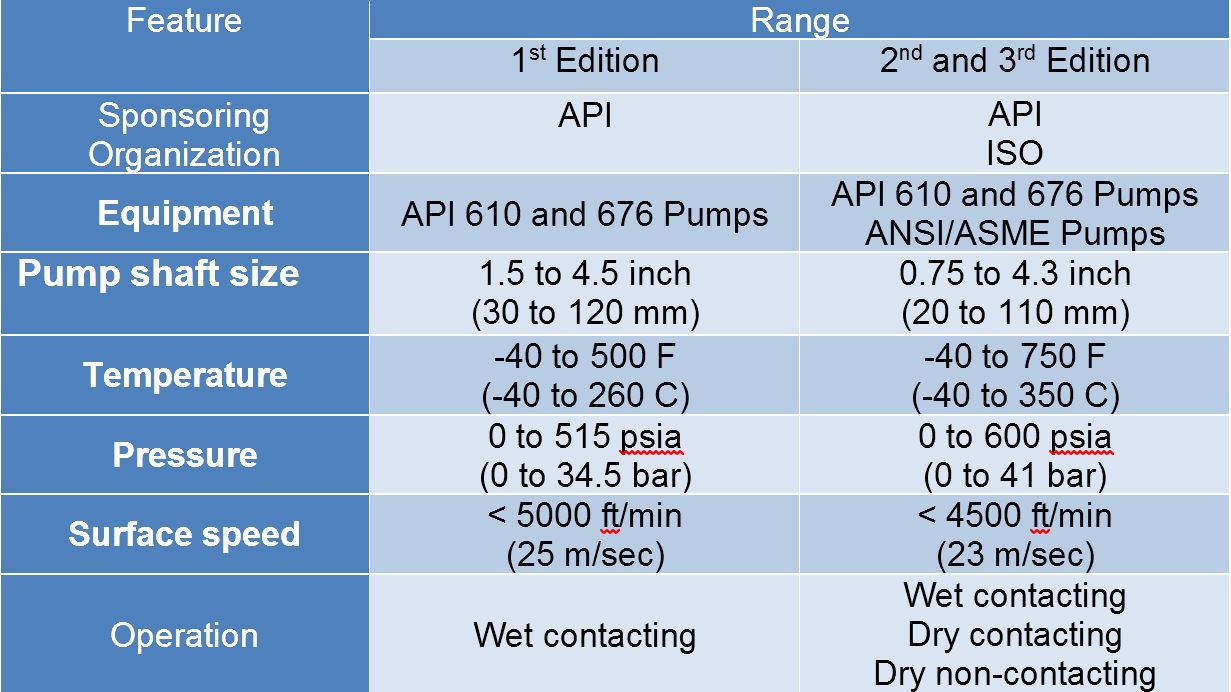
After more than five years of planning, the American Petroleum Institute (API) is preparing to release the 4th edition of API Standard 682 (ISO 21049:2011). The API 682 standard, which dates back to 1994 and is formally known as Shaft Sealing Systems for Centrifugal and Rotary Pumps, offers specifications and best practices for mechanical seals and systems to pump end users.
The standard’s latest edition began to take shape in 2006, when API formed a 4th edition task force to respond to end users’ questions and comments about previous editions. The task force soon realized that major changes, including reorganization and editing, would be necessary. While addressing every aspect of the resulting 4th edition (which is more than 250 pages long) would be impossible, this article summarizes the standard’s main points.
Those who use API 682 should understand the standard’s scope and remember that the standard does not include specifications for equipment outside that scope, such as engineered seals or mixers. Another important but often misunderstood point is that API 682’s figures are illustrative and not normative in their entirety.
For example, one of API 682’s figures shows a fixed throttle bushing combined with a rotating Type A seal, but seal manufacturers do not always have to combine these two components. The standard provides normative details in clauses and tables to help purchasers distinguish between requirements and suggestions.
The 4th edition continues to divide seals into three categories, three types and three arrangements. For all practical purposes, seal manufacturers can combine a seal’s component parts into nearly any orientation or configuration. Each orientation and configuration has advantages and disadvantages with respect to certain applications, performance and system disturbances.
Before the 4th edition, API 682 did not specify a minimum clearance between the inside diameter of a stationary seal part and the outside diameter of a rotating seal part. The 4th edition specifies this minimum clearance—typically the clearance between the sleeve and the mating ring. The specified clearances are representative of standard clearances that end users have used for decades. End users should not consider seal components to be “shaft catchers” to restrict shaft movement. The minimum clearance specified in API 682 also applies only to equipment within the standard’s scope. Equipment outside that scope, such as non-cartridge seals, older pumps, non-API 610 pumps and certain severe services, might benefit from larger clearances.
The new standard also updates the default bushings for the gland plate for the three seal categories. Fixed throttle bushings are now the default for Category 1 only, while floating bushings are the default for Categories 2 and 3.
While the 4th edition features the recommended seal selection procedure from the standard’s first three editions, it adds an alternative selection method in Annex A. Proposed by task force member Michael Goodrich, this alternative method recommends using material data sheet information to select a sealing arrangement.
Plans 66A and 66B are new to the standard, although end users have used them previously in pipeline applications. These plans detect and restrict excessive leakage rates in case of an Arrangement 1 seal failure.
The 4th edition has revised the data sheets in Annex C extensively to make them the same for all seal categories. Only two data sheets are included in the 4th edition—one in metric units and one in U.S. customary units. The new edition also folds Annex J into Annex E.
Previous editions of API 682 required metal plugs and anaerobic sealants when shipping new or repaired cartridges. After much debate, the task force decided that threaded connection points should be protected with plastic plugs for shipment. These plastic plugs should be red and have center tabs that operators can pull easily to distinguish the plugs from metal plugs. Shippers should also attach yellow warning tags to the plugs to indicate that end users need to remove the plugs before operation.
Although tutorial notes are scattered throughout API 682, this edition expands the tutorial section, Annex F, from seven pages to 42 pages. The expanded annex includes illustrative calculations. In particular, users interested in systems such as Plan 53B will find Annex F to be useful.
The 4th edition of API 682 is the product of more than 20 years of discussion, debate, usage and peer review. It includes a strong set of defaults and is by far the best and most logical starting point for mechanical seal and systems use. Equipment operators should take the time to familiarize themselves with API 682 to get the most out of this comprehensive standard.
The RO-FT between-bearing configuration provides a reliable, robust and easy to maintain pump for the midstream and downstream refining, petrochemical and chemical processing industries. Designed specifically for demanding low-flow high-head services, this pump fully meets the requirements of API 610. The operating characteristics of the Roto-Jet® RO-FT API 610 pump are simple and similar to a conventional centrifugal pump. Energy is added to the fluid via the rotor, and the stationary Pitot tube converts the fluid velocity energy into static pressure. In addition, the Roto-Jet® RO-FT API 610 pump has been specifically designed to achieve a broad operating range without generating damaging hydraulic forces during a process upset. These attributes result in improved mechanical seal and bearing life to maximise Mean Time Between Failure, and decrease operational and maintenance costs, which make the Roto-Jet the most cost effective choice for low-flow high head process applications.
The MP52 series aligns with API 682 Plans 52 and 53A. The Plan 52 is designed to support liquid buffer fluid for a containment seal chamber that is below the seal chamber pressure. The Plan 53A is a pressurized system designed to isolate the seal from the process completely by providing liquid barrier fluid at a pressure higher than the seal chamber.
Our seal reservoirs are built to ASME Section VIII standards and are available with ASME U code stamps. Flexaseal Engineered Seals and Systems, LLC provides standard and custom buffer fluid reservoirs that meet API 682 Standards. As an industrial seal pot manufacturer for the chemical, petrochemical, and industrial industries, our seal pot systems help protect the environment and your workers from hazardous materials.

First Introduced in 2000 the API 685 standard describes requirements for sealless centrifugal pumps for petroleum, heavy-duty chemical, and gas industry services. API 685 is the sealless pump equivalent to API 610, which is well known and accepted as industry standard for sealed centrifugal pumps for many years.
By eliminating the requirement for costly mechanical shaft seals and complicated seal flush plans Klaus Union"s SLM-AVP range provides a more reliable, safer and more cost effective solution for many critical applications – 100 % emission free.
A wide variety of over 30 available AVP-hydraulics from a 1.5X1X6 to a 16X16X20 cover flow rates up to 18,000 GPM sealless – ideal for handling critical liquids where leakage cannot be tolerated.

ANSI and API are two process pump styles that are sometimes confused. This uncertainty can lead to users choosing a less expensive ANSI pump when the application demands API (or at the very least, an API pump could do the job more efficiently at a lower operating cost). Less often, a user may choose the more expensive API pump when an ANSI pump could effectively handle the job.
In recent years there has been much discussion on adapting ANSI pumps for expanded use in the oil and gas industry—the domain of the API pump. To meet the environmental demands of the field, the pumps must meet additional standards such as reliability in extreme conditions.
API pumps meet Standard 610 for General Refinery Service as set by the American Petroleum Institute (API). This U.S. trade association for the oil and natural gas industries develops standards for petroleum and petrochemical equipment.
Unlike the ANSI standards, which are dimensional, API Standard 610 centers around the pump’s construction and design, particularly as they pertain to the pump’s ability to handle high temperatures, pressures and emissions.
API pumps are the choice for more aggressive applications in the oil refinery industry. Their casings, bearing houses, mounting feet and back cover arrangement are all designed for maximum efficiency and reliability in oil refinery applications, as well as controlling emissions and safely handling fluids that can cause environmental damage.
In general, ANSI pumps provide reliable service across a range of applications and are the pump of choice for chemical processing. They offer tremendous flexibility and ease of operation. API pumps are heavier duty and should be considered for higher pressure and temperature applications. They are the pump of choice for aggressive oil refinery processes.
For assistance choosing an ANSI or API pump, the experts at C&B are here to help. Let us help you find the best fit for your application.Contact ustoday.


 8613371530291