
api 682 mechanical seal in stock
The AESSEAL® API Type A, B and C single-seal range offers the user an unprecedented range of API engineered sealing solutions to suit all application requirements. The category 1, 2 and 3 seals are qualification tested to API 682. Modular design allows the users to select the right solution for their application, with the modular design ensuring simplicity of purchase and fast delivery.
Thin cross-section (TXS) seal designs for mature asset installation including API 610, 5th Ed. with a 0.500" (12mm) radial cross-sectional space between the shaft and seal chamber
World-leading bi-directional pumping ring performance with 0.062” (1.5mm) radial clearance between rotor and stator; conforming with API 682 Section 8.6.2.3 without compromise
World-leading bi-directional pumping ring performance with 0.062” (1.5mm) clearance between rotor and stator, conforming with API 682 Section 8.6.2.3 without compromise
Also available CAPI-74 a face to face, category 2 & 3 seal. The CAPI-74 is a non-contacting dual seal designed for pumps meeting ANSI/API standard 682. Dual pressurized dry gas seals are becoming more common in the Oil and Gas industry and can provide zero process emissions in service. For more information visit the capi-74 product page
In many cases, Cartridge Seals may contain the exact same major items that are sold separately as Component Seals. These pieces include the Rotary Seal and Stationary Face as well as other minor parts like O-rings or Gaskets all required at assembly. The advantage of using a Cartridge Seal is that the time required for installation, and even more importantly, the possibility of error during installation is dramatically reduced. When installing a Cartridge Seal, the necessity of having to measure internal components positioning on the shaft to achieve proper face loading is eliminated. Cartridge Seals come pre-assembled from the factory with all internal components assembled with proper face loading and all pieces in place, exactly where they should be. Cartridge Seals eliminate the need to handle delicate, polished parts such as Seal Faces that can be compromised by the presence of dirt, smudges and oils that can result from handling during assembly. So, for the easiest and most reliable Seal installation, Cartridge Seals go a long way towards helping you achieve trouble free startup and extended service life from your equipment.
John Crane brings you the world’s most complete selection of performance-proven edge-welded and formed metal bellows sealing products used in a wide range of rotating equipment such as pumps, compressors, mixers, and agitators. Our experience in diverse industries such as oil & gas, petrochemical, chemical, refrigeration compressor, pharmaceutical, food processing, pulp & paper, and more have proven the soundness of John Crane’s metal bellows design.

A sealing system, consisting of a mechanical seal and an associated supply system that is balanced by individual applications, is the utmost guarantee for a reliable sealing point and uninterrupted pump service. The performance of the seal is greatly influenced by the environment around the seal faces, making the provision of suitable, clean fluids as well as a moderate temperature an essential topic.
This guiding booklet provides a condensed overview of all piping plans established by the API 682 4th edition guidelines. Each illustrated piping plan is briefly described, and a recommendation that considers the media characteristics in terms of the relevant application and corresponding configurations is given to help you reliably select your sealing system. Furthermore, the content of this booklet has been enriched by providing clues – so-called ‘remarks and checkpoints’ – where EagleBurgmann shares the experiences gained from multiple equipped plants.
Several factors play a major role when choosing the product, the product type, the materials used and how it is operated: process conditions at the sealing location, operating conditions and the medium to be sealed.
No matter what requirements our customers have, EagleBurgmann understands how these factors affect functionality and economic viability, and they translate this expertise into outstanding long-term, reliable sealing solutions. EagleBurgmann has all the expertise needed to manage and support the entire development, life and service cycle of its sealing solutions.
EagleBurgmann offers customers the widest product portfolio of seals and seal supply systems according to API 682 4th edition. The configurations listed for each individual piping plan are to be understood as recommendations including possible utilizations which may also be applied.
EagleBurgmann is one of the internationally leading companies for industrial sealing technology. Their products are used wherever safety and reliability are important: in the oil and gas industry, refining technology, the petrochemical, chemical and pharmaceutical industries, food processing, power, water, mining, pulp & paper and many others. More than 6,000 employees contribute their ideas, solutions and commitment towards ensuring that customers all over the world can rely on their seals and services. More than 21,000 EagleBurgmann API-seals and systems are installed world-wide.

Mechanical seal failure due to unfavorable operating conditions is an issue in every industry. Double mechanical seals especially require proper sealing accessories to create suitable operating environments which are key to increasing MTBF. Reservoir systems are one of the most common and effective options to supply cooling fluid crucial to successful seal operation.
A double -or dual – cartridge seal is defined as an arrangement of two mechanical seals in a series. These seals may be configured in various orientations within the cartridge. The seals themselves are referred to as the “primary” (or inboard) seal and the “secondary” (or outboard) seal. A double seal arrangement is the superior option to a single cartridge when it is imperative the product being pumped does not leak into the atmosphere. The API (American Petroleum Institute) Standard 682 classifies dual seals into two configurations. These configurations also apply to ASME (American Society of Engineers) B73.1 and ASME B73.2 pump designs.
Arrangement 2 (Unpressurized) Designs: the buffer fluid is the operating environment for the secondary seal and forms a “buffer” between the process fluid and the atmosphere.
Arrangement 3 (Pressurized) Designs: the barrier fluid is the operating environment for both the inboard and outboard seal, preventing process leakage to the atmosphere.
Buffer and barrier fluids may be either liquid or gas. These fluids lubricate seal faces during operation as well as regulate operating temperatures by moving heat—both generated and absorbed—away from the faces.
Seal support systems are necessary for the smooth operation of a dual mechanical seal. Here are two of the most common piping plans for these systems.
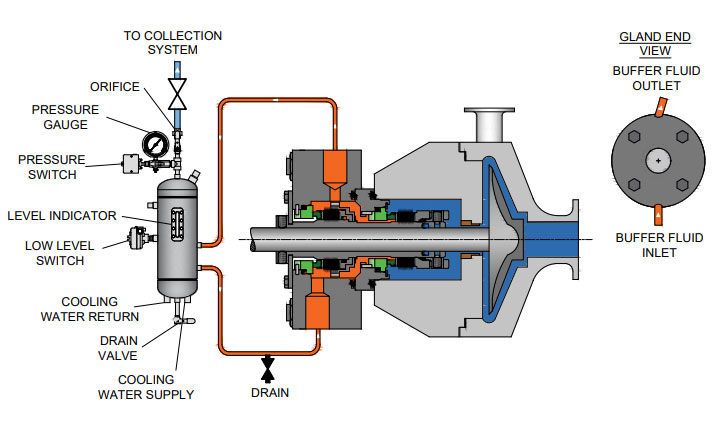
This is an unpressurized system consisting of a reservoir, supply and return lines, and an internal circulation device within the outer seal (commonly referred to as a pumping ring). The buffer fluid circulation rate is dependent on how this circulation device functions during seal operation.
Reservoirs may be fitted with a variety of measurement devices such as a liquid level indicator and pressure gauges as well as valves and switches to aid in various operation and maintenance functions. For instance, a typical support system configuration for natural gas liquids (NGL) would issue an alarm (visual, audible, or both) when the inner seal fails. In addition, the outer seal would take over the primary seal function until maintenance is performed.
This system forces gas from an external pressurized source into the reservoir to pressurize the barrier fluid. This means the reservoir pressure will be above seal chamber pressure; a guideline is a minimum of 20 to 25 psig (1.4 to 1.73 bar) above the maximum process pressure.
The Plan 53A is also used to maintain a specific operating temperature range to ensure optimum lubrication at the seal faces. The reservoir houses a cooling coil which actively cools the barrier fluid as necessary.
As with the Plan 52, a circulation device is used to move the barrier fluid. Replenishing a Plan 53A system with fresh barrier fluid can be as simple as a using a hand pump or a more complex arrangement which satisfies multiple seals.
Liquid-lubricated dual mechanical seals require an external source of clean, cool lubricating fluid. The following fluid reservoir systems create this enhanced sealing environment, enabling longer operational life for dual seals.
In the oil and gas industry, reliable seal operation is critical to running efficient, safe processes. In conjunction with API 682 Piping Plans 52 and 53A, seal support systems aid in smooth seal operation.
If you require an engineered seal support system or are interested in additional options to Flexaseal’s ANSI PLUS and ANSI LITE support systems, please contact our applications engineering team.
Mechanical seals became the dominant sealing technology in refineries and chemical plants in the 1980s, causing the American Petroleum Institute (API) to establish a committee whose sole focus was to write standards for these components. The first edition, API 682 Shaft Sealing Systems for Centrifugal and Rotary Pumps was published in 1994 with this mission statement, “This standard is designed to default to the equipment types most commonly supplied that have a high probability of meeting the objective of at least three years of uninterrupted service while complying with emissions regulations."Currently in its fourth edition, API 682 continues to offer guidance based on process service for both mechanical seals and their support systems.
While much of the standard is focused on mechanical seals, a significant portion is devoted to seal support systems, as they are a critical component to the proper functioning of the seal and pump system. As a manufacturer of seal support systems, Swagelok Company and our sales and service centers have implemented the best practices of API 682 4th Edition. In this blog post, we will explain what some of those best practices are, and how implementing recommendations from the standard in the construction and design of your seal support systems can help you meet your goals of increasing reliability and safety while reducing costs.
Before we discuss best practices, let’s look at the functions of seal support systems. These systems are designed for a specific mechanical seal and set of process conditions. Typically, they supply either a gas or a liquid to the mechanical seal to regulate the environment in which the seal operates, protecting rotating equipment from damage.
Throughout API 682 4th Edition, there are references to reducing the number of connections in seal support systems. Whether welded pipe or tubing is selected for the system, threaded systems are discouraged. Every connection can be viewed as a potential leak point and possible reliability risk in hydrocarbon pumping applications. Leaks on seal support systems near pumps can cause asset damage, increased downtime, environmental issues, and safety risks.
In the past, many seal support systems were constructed out of pipe due to piping being historically preferred. More recently, seal manufacturers, end users, and pump OEMS have implemented tubing as a connection solution in seal support systems due to its long history of successful use in critical applications throughout the industrial world. As rotating equipment expert Heinz Bloch noted in a recent Hydrocarbon Processing article, “[the] American Petroleum Institute Standard 682 (API 682) began to endorse the use of tubing for some seal piping plans. Regrettably, tradition-bound purchasers still opt for hard pipe; we are asking them to reconsider. API 682 (4th Edition) now specifies seal support system connections almost interchangeably.”
Tubing can be utilized to reduce the number of connections by bending lines and appropriately using adapter fittings. Often, the only needed connections are those at the seal and the sealing system. Since tubing is annealed, bending the tubing work hardens the metal, increasing the strength of the tube at the bend. Innovative connection technologies such as flange adapters and extended male connectors further reduce the number of connections from threaded ports on the seal and seal pots by eliminating the need for multiple fittings. The use of tubing provides further financial benefit when we examine the MRO costs of the pump, seal, and support system. During maintenance operations where “piping” around pumps is reworked, the use of tubing eliminates the need for costly on-site welding and can be installed quickly to reduce downtime.
Seal support systems are critical to the proper operation of the seal and pump, and as such, require regular visual inspection. Making the job of visual inspection simple promotes system reliability and safety. When designing seal support systems, there are several best practice design principles to consider once the piping plan and general arrangement have been selected.
Mechanical seals are often damaged when pumps are started and stopped, sometimes as the result of improper seal support system operation. If the design of the seal support system facilitates proper operation, common mistakes when commissioning pumps can be avoided.
Additionally, API 682 supports these design considerations. It states: “All controls and instruments shall be located and arranged to permit easy visibility by the operators, as well as accessibility for tests, adjustments, and maintenance” (9.1.5)
Lastly, panels can include part numbering information, flow path indication, and operator instructions. These improvements help ensure safe and reliable startup and shutdown of pumps and seal support systems.
API 682 4th Edition also recommends block-bleed configurations for all gauges. If systems are not designed with this feature, it is likely that as gauges fail, operators will be left without critical information until the next turnaround or project when the pump and support system can be decommissioned and the gauge replaced.
Lastly, there are a wide variety of tubing connections and design options that allow for every serviceable component on a seal support system to be easily removed and replaced while continuing to operate the system. For seal pots, the 4thEdition stipulates “Local operation, venting, filling, and draining shall be accomplished from grade. Unless otherwise specified, systems that require the use of a ladder or step or that require climbing on the baseplate or piping are not acceptable” (8.1.8) .
Implementing these basic best practice design principles for mechanical seal support system increases reliability and reduces costs. To recap how you can realize better results with your systems:
Bringing pumps offline to fix minor instrumentation issues or fill seal pots should not be acceptable. Locating these systems on panels, with proper labeling and designing for easy maintenance reduces the chance for operator error which can damage seals.
Seal failures and the associated costs of seal replacement should be of great concern to rotating equipment groups at all plants. Ensuring that the best practices and design principals of API 682 4th Edition are followed helps prevent these costs and creates a safer and more reliable operation.
Swagelok provides design and assembly of seal support systems through our network of more than 200 authorized sales and service centers. We offer configurable, local, and reliable systems that are better by design to help you reduce costs, save time, and improve safety of your rotating equipment.
For additional advice on designing and installing your mechanical seal support systems, or to find the right API seal plan kits or assemblies for your applications, reach out to your local Swagelok team.

The TF PJ05D Dual Cartidge-Style Bellows Seal is designed for applications in which the process fluid is incompatible with common elastomers or where the cost of custom O-Rings is prohibitive. The PJ05D Bellows Seal is used primarily in the chemical and petrochemical industries.

API Standard 682, titled "Pumps - Shaft Sealing Systems for Centrifugal and Rotary Pumps," is the American Petroleum Institute (API) standard for end-face mechanical seals.centrifugal pumps. It is based on the combined knowledge and experience of seal manufacturers, engineering companies, and end users. API 682 is primarily intended for use in the petroleum, natural gas and chemical industries, but is often referenced for other types of equipment and industries.
By the late 1980s, mechanical seals had been accepted as the preferred method for sealing rotating pumps for many years. However, mechanical seal standards were generally buried in other standards such as DIN 24960, ANSI B73, and API 610. All of these standards were primarily pump standards and any references to seals were directed at how mechanical seals would interact with pumps.
API 610 is the API standard about centrifugal pumps and is primarily intended for use in the petroleum, natural gas and chemical industries. Although the 1st through 7th Editions of API 610 included specifications for mechanical seals, beginning with the 8th Edition, API 610 defers to API 682 for seal specifications.
In the late 1980s a group of refinery equipment engineers and managers began to compare sealing solutions in refinery applications. This group, led by V. R. Dodd of Chevron, came up with a general plan and the American Petroleum Institute (API) agreed to establish a standard for mechanical seals: API 682. A Task Force was formed in 1990 and the first meeting was held in January 1991. This Task Force was composed of fourteen members from various refineries, seal and pump manufacturers. API 682, First Edition, was published in October 1994.
One interesting aspect of API 682 is that it includes a strong set of defaults. That is, unless the user indicates otherwise, API 682 makes default choices for specifics such as:
Some statements within API 682 are normative, that is, required, whereas others are informative, that is, descriptive but not required. In particular, many of the illustrations are informative. This distinction has not always been apparent to the reader.
The first edition of API 682 was entirely new although parts of it were extracted from the pump standard API 610 and existing API standard paragraphs.
Although this mission statement no longer appears in the standard, it remains the basic principle driving the work of the API 682 Task Force and its relevance remains the same for the 4th Edition as it did for the 1st.
In addition to providing requirements for mechanical seals, the 1st Edition of API 682 also provided a guide on how to select the correct seal for a number of common refinery applications. In order to provide this seal selection guide, it was necessary to categorize applications into a number of services:
Prior to API 682, 1st Edition, multiple seals were designated as being either “tandem” or “double” seals; however, advances in seal design had rendered these classic terms obsolete. As a result, there was some confusion on how multiple seals were designated. The task force decided to use a more descriptive designation and chose to define dual seal arrangements. A dual seal would be two sets of sealing faces used in the same seal chamber. The fluid between these two sets of sealing faces could be either pressurized or unpressurized. Three standard arrangements were defined:
After having defined the services, seal types, and seal arrangements, a series of flowcharts were created to help in selecting a seal type, special materials or design requirements, and supporting piping plans.
API 682 seals were to have a high probability of three years of reliable service. In order to prove this, seal performance testing on process fluids under representative pressures and temperatures was required. These performance tests are called “Qualification Tests”.
The general idea of the qualification test was to prove that the design was sound. The goal of the qualification test was to simulate a long-term steady state run followed by a process upset. The simulated process upset consisted of pressure changes, temperature changes and included loss of flush. The results of these tests were made available to the purchaser for evaluation. There was no acceptance criteria presented in API 682 1st Edition.
In addition to the qualification test of the design, every API 682 seal, whether new or repaired, is to be pressure tested with air before being shipped to the end user.
One of the major criticisms of API 682 1st Edition was that all the seals were “heavy duty” and therefore expensive with no alternatives for easy services. To some degree, this was intentional and was done in order to reduce inventory, promote familiarity with a limited number of seal types and to increase reliability. Another criticism of API 682 1st Edition was that it considered only API 610 pumps and only refinery applications. The chemical and petrochemical industries routinely use ASME pumps in addition to API 610 pumps. Broadening the scope of pumps covered by API 682 would allow standardized seals to be applied in a greater number of industries.
In 2nd Edition, the organization of API 682 was changed to conform to ISO standards: This reorganization means that there is no simple cross reference guide between 1st edition and 2nd edition paragraph numbers.
The 2nd Edition introduced the concept of seal categories. A seal category describes the type of pump into which the seal will be installed, the operating window, the design features, and the testing and documentation requirements. There are three categories designated as Category 1, 2, or 3.
Category 1 seals are intended for non-API-610 pumps. This category is applicable for temperatures between –40°F and 500°F (-40°C and 260°C) and pressures to 315 PSI (22 bar).
Category 2 seal are intended for API-610 This category is applicable for temperatures between –40°F and 750°F (-40°C and 400°C) and pressures to 615 PSI (42 bar).
Category 3 seals are essentially the original seals of 1st Edition and are also intended for API-610 pumps. Category 3 seals are intended for the most demanding applications. This category is applicable for temperatures between –40°F and 750°F (-40°C and 400°C) and pressures to 615 PSI (42 bar). Design features include a distributed flush and floating throttle bushing for single seals. Additional documentation must be also provided.
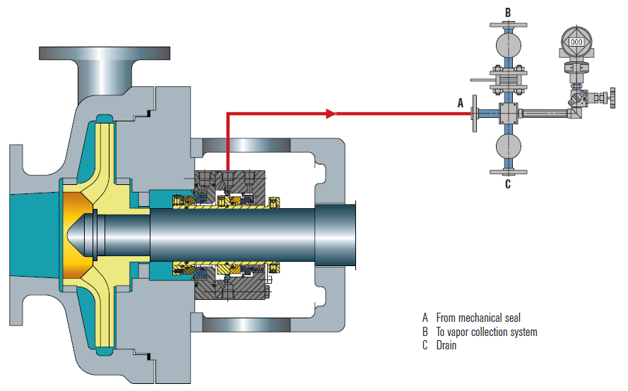
Containment seals are the outer seal of Arrangement 2. In the 2nd Edition, containment seals can be used with a liquid buffer fluid, a gas buffer fluid or without a buffer fluid. In the case of a dry running containment seal, the containment seal will be exposed primarily to buffer gas or vaporized process fluid. Such containment seals must therefore be designed for continuous dry running while meeting the reliability goals of the standard. Dry running containment seals may be either contacting or non-contacting.
Non-contacting inner seals are also introduced for Arrangement 2. One of the primary targets for non-contacting inner seals is in flashing hydrocarbon services. In some of these services, it is impossible to obtain adequate vapor margins to prevent flashing of the fluid in the seal chamber. This seal will be used with a dry running containment seal and the leakage past the inner seal will be piped to a vapor recovery system.
The other new seal type introduced in 2nd Edition was the dry running gas seal used in Arrangement 3. This seal is designed to run on a gas barrier fluid such as nitrogen.
Several new piping plans were introduced in the 2nd Edition. These included additional options for dual pressurized liquid seals as well as new piping plans to support containment seals and dual pressurized gas seals.
One of the strengths of the 1st Edition was to provide qualification tests in which seal vendors would be required to prove the suitability of their seals for a given service. The 2nd Edition expanded on these requirements by adding new tests for containment seals and dual gas seals as well as defining acceptance criteria for all tests.
For all practical purposes, API 682 3rd Edition is the same as 2nd Edition. The completed 2nd Edition was submitted to the ISO Organization for approval as their ISO 21049. At the time, API and ISO had an agreement to jointly issue standards. The ISO Organization made slight editorial changes to 2nd Edition, including correcting typographical errors and unit conversions. Therefore, API had to re-issue a corrected 2nd edition but choose to label it as 3rd edition. API 682 3rd Edition was published in September 2004.
API and ISO no longer have the agreement to jointly issue standards. The 2004 issue of ISO 21049 is the only issue and plans to update it are unknown.
Seal Configuration refers to the orientation of the seal components in an assembly. In previous editions, orientations were defined as face-to-back, back-to-back, and face-to-face and these terms are carried over into the 4th Edition. In 4th Edition, any orientation (face to back, back to back, face to face) can be used in a dual seal provided that the design features are appropriate to the functionality of that particular arrangement.
Fourth Edition added additional specifications for clearances, placed these requirements in the form of tables and noted that seal components are not to be considered as “shaft catchers” to restrict shaft movement. The minimum clearances specified apply only to equipment within the scope of the standard. Equipment outside that scope, such as non-cartridge seals, older pumps, non-API 610 pumps and certain severe services, might benefit from larger clearances.
Before API 682, API 610 (the pump standard) used a simple seal code to specify seals. API 682 attempted to use a more comprehensive seal code; however, that code changed with every edition of API 682. The 4th Edition code, described in Annex D, is probably the best to date and includes some concepts and codes from the historical API 610 seal code.
API standards are reviewed every five years and re-issued every ten years. A new Taskforce for API 682 was formed in 2017 and preparations for 5th Edition are underway.
Buck, G. S., Huebner, M. B, Thorp, J. M., and Fernandez, C. L. “Advances in Mechanical Sealing – An Introduction to API-682 Second Edition”, Texas A&M Turbomachinery Symposium, 2003.
API Standard 682, Second Edition, 2001, “Pumps – Shaft Sealing Systems for Centrifugal and Rotary Pumps,” American Petroleum Institute, Washington, D.C.
API Standard 682, Third Edition, 2004, “Pumps – Shaft Sealing Systems for Centrifugal and Rotary Pumps,” American Petroleum Institute, Washington, D.C.
API Standard 682, Fourth Edition, 2014, “Pumps – Shaft Sealing Systems for Centrifugal and Rotary Pumps,” American Petroleum Institute, Washington, D.C.
The Chesterton A2382 Cartridge Dual Seal is designed specifically for stringent refinery applications, meeting the API 682 Standard, Type A pusher seal requirements. Our superior API seal combines proven Chesterton technology and extensive R&D qualification testing. The A2382 Seal design delivers high reliability and meets tough emissions requirements through advanced seal face design and low heat generation.
Chesterton"s API seals provide a versatile approach to refinery, chemical, and petrochemical sealing. The A2382 is a double-balanced seal designed to handle pressure reversals. The innovative design simplifies seal selection and improves standardization throughout the plant. API 682 and ISO 21049 compliant.

Swagelok’s standard designs can quickly and easily be configured to meet your specific needs whether single-seal, dual-seal, quench or gas seal. Our plans meet API 682 standards that support the use of tubing instead of piping, reducing potential leak points and providing enhanced vibration resistance.
Watch episode 5 of Swaging with Garyas he interviews Technical Advisor JakeJones, a former millwright, and I&E tech and planner, with one of the largest rubber plants on the Gulf Coast about the benefits of Swagelok"s Seal Support Systems.
Kits adhere to API best practices by showing technicians where to bend tubing to eliminate potential leak points through the reduction of elbow fittings and pipe threads.

The APILITE (R) mechanical seal is a new addition to the API 682 RDT cartridge seal family. It is designed for sealing heavy and light hydrocarbons, including VOCs, and other hazardous fluids at oil refineries and petrochemical plants, gas plants, and chemical plants. APILITE RDT seal is an o-ring dual seal to be used with API Plan 52, 53, or 54.
Minimized bending of seal rings allows for stable operation under higher pressures and for longer MTBR (mean time between repair) because of less wear;
Interchangeability of many parts and design solutions with the SD APITERM seal reduces inventory of spare parts, lets the seal survive under pump dry-running, and decreases prices by encreasing parts production volume;


 8613371530291