
api 682 mechanical seal data sheet excel quotation
As a means of quantifying the amount, or percent, of balance for a mechanical seal, a ratio can be made between the seal face area above the balance diameter versus the total seal face area. This ratio can also be expressed as the area of the seal face exposed to hydraulic closing force versus the total seal face area.
As a general rule of thumb, balanced seal designs use a balance ratio of 0.75 for water and non flashing hydrocarbons. For flashing hydrocarbons, which are fluids with a vapor pressure greater than atmospheric pressure at the service temperature, the balance ratio is typically 0.80 to 0.85. Unbalanced seal designs typically have a ratio of 1.25 to 1.35.
Balance diameter varies with seal design, but for spring pusher seals under outer-diameter pressure, it is normally the diameter of the sliding contact surface of the inner diameter of the dynamic O-ring; for spring pusher seals under inner-diameter pressure, it is normally the diameter of the sliding contact surface of the outer diameter of the dynamic O-ring; for welded metal bellows-type seals, the balance diameter is normally the mean diameter of the bellows, but this can vary with pressure.
Temperature control plays an important role in the success of a mechanical seal. Every seal generates heat at the seal faces. In some cases, heat soak from the fluid pumped should also be controlled. Heat soak is the heat transferred from the pump and pumped fluid to fluid in the seal chamber. For example, if a particular fluid must be maintained at 60 °C (140 °F) to maintain a satisfactory vapour pressure margin and the pump operating temperature is 146 °C (295 °F), heat would be transferred through the pump case into the seal chamber.

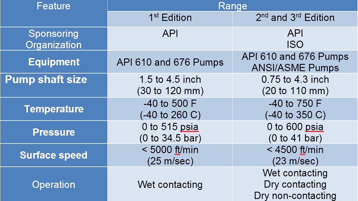
After more than five years of planning, the American Petroleum Institute (API) is preparing to release the 4th edition of API Standard 682 (ISO 21049:2011). The API 682 standard, which dates back to 1994 and is formally known as Shaft Sealing Systems for Centrifugal and Rotary Pumps, offers specifications and best practices for mechanical seals and systems to pump end users.
The standard’s latest edition began to take shape in 2006, when API formed a 4th edition task force to respond to end users’ questions and comments about previous editions. The task force soon realized that major changes, including reorganization and editing, would be necessary. While addressing every aspect of the resulting 4th edition (which is more than 250 pages long) would be impossible, this article summarizes the standard’s main points.
Those who use API 682 should understand the standard’s scope and remember that the standard does not include specifications for equipment outside that scope, such as engineered seals or mixers. Another important but often misunderstood point is that API 682’s figures are illustrative and not normative in their entirety.
For example, one of API 682’s figures shows a fixed throttle bushing combined with a rotating Type A seal, but seal manufacturers do not always have to combine these two components. The standard provides normative details in clauses and tables to help purchasers distinguish between requirements and suggestions.
The 4th edition continues to divide seals into three categories, three types and three arrangements. For all practical purposes, seal manufacturers can combine a seal’s component parts into nearly any orientation or configuration. Each orientation and configuration has advantages and disadvantages with respect to certain applications, performance and system disturbances.
Before the 4th edition, API 682 did not specify a minimum clearance between the inside diameter of a stationary seal part and the outside diameter of a rotating seal part. The 4th edition specifies this minimum clearance—typically the clearance between the sleeve and the mating ring. The specified clearances are representative of standard clearances that end users have used for decades. End users should not consider seal components to be “shaft catchers” to restrict shaft movement. The minimum clearance specified in API 682 also applies only to equipment within the standard’s scope. Equipment outside that scope, such as non-cartridge seals, older pumps, non-API 610 pumps and certain severe services, might benefit from larger clearances.
The new standard also updates the default bushings for the gland plate for the three seal categories. Fixed throttle bushings are now the default for Category 1 only, while floating bushings are the default for Categories 2 and 3.
While the 4th edition features the recommended seal selection procedure from the standard’s first three editions, it adds an alternative selection method in Annex A. Proposed by task force member Michael Goodrich, this alternative method recommends using material data sheet information to select a sealing arrangement.
Plans 66A and 66B are new to the standard, although end users have used them previously in pipeline applications. These plans detect and restrict excessive leakage rates in case of an Arrangement 1 seal failure.
Nonetheless, the change from simple switches to transmitters is likely to be controversial and expensive. If purchasers want to continue to use switches, they now have to request them in their specifications or data sheets.
The 4th edition has revised the data sheets in Annex C extensively to make them the same for all seal categories. Only two data sheets are included in the 4th edition—one in metric units and one in U.S. customary units. The new edition also folds Annex J into Annex E.
Previous editions of API 682 required metal plugs and anaerobic sealants when shipping new or repaired cartridges. After much debate, the task force decided that threaded connection points should be protected with plastic plugs for shipment. These plastic plugs should be red and have center tabs that operators can pull easily to distinguish the plugs from metal plugs. Shippers should also attach yellow warning tags to the plugs to indicate that end users need to remove the plugs before operation.
Although tutorial notes are scattered throughout API 682, this edition expands the tutorial section, Annex F, from seven pages to 42 pages. The expanded annex includes illustrative calculations. In particular, users interested in systems such as Plan 53B will find Annex F to be useful.
The 4th edition of API 682 is the product of more than 20 years of discussion, debate, usage and peer review. It includes a strong set of defaults and is by far the best and most logical starting point for mechanical seal and systems use. Equipment operators should take the time to familiarize themselves with API 682 to get the most out of this comprehensive standard.
This website is using a security service to protect itself from online attacks. The action you just performed triggered the security solution. There are several actions that could trigger this block including submitting a certain word or phrase, a SQL command or malformed data.

All Flopac seal support systems, refill units, and heat exchangers we design and produce ourselves. That in comparison to the many seal support products being sold that are not made by the companies shown on the logo. In a way, it should not matter who markets these products, as long as your partner is committed, the products reliable, perform well, and value for money. Precisely the point! Ensure to have it all and address Flopac. With all the clear benefits of buying directly from the manufacturer:
Seal support systems and related equipment are our sole purpose. In order to exist, and in order to create our distinctive profile, this is where we need to excel. – All the time!
Commitment is the driving philosophy we act on since the founding of Flopac in 1995. Our goal is to be seen as the world’s best and most reliable supplier of engineered API 682 seal support systems and related products such as make-up/refill units. In a market that is characterized by high-mix/low-volume manufacturing – small batches of customized technical products. That calls for a specialist manufacturer. One who understands that flexibility is key. With absolutely no compromise to quality or performance. A partner that is responsive. Able to make on-the-spot decisions. And keeps production moving all the time. A partner in control, committed all the time.
Commitment is the driving philosophy we act on since the founding of Flopac in 1995. Our goal is to be seen as the world’s best and most reliable supplier of engineered API 682 seal support systems and related products such as make-up/refill units. In a market that is characterized by high-mix/low-volume manufacturing – small batches of customized technical products. That calls for a specialist manufacturer. One who understands that flexibility is key. With absolutely no compromise to quality or performance. A partner that is responsive. Able to make on-the-spot decisions. And keeps production moving all the time. A partner in control, committed all the time.
Flopac ® excellent service is something that you will experience in every contact you will have with our company. Form the designers, technical engineers, account managers, all the way up to our customer service. We manage all your order related legal and technical specialized documentation. That means all the pressure equipment, quality dossiers, welding, and instrumentation specifications, etc. An excellent service level we are proud to maintain far beyond equipment delivery.
Flopac ® excellent service is something that you will experience in every contact you will have with our company. Form the designers, technical engineers, account managers, all the way up to our customer service. We manage all your order related legal and technical specialized documentation. That means all the pressure equipment, quality dossiers, welding, and instrumentation specifications, etc. An excellent service level we are proud to maintain far beyond equipment delivery.
Is good, good enough for you? Sure, our ISO 9001 certified management system ensures Flopac’s consistent provision of products and services that meet customer and applicable statutory requirements, while facilitating opportunities to enhance customer satisfaction. But we believe more is needed to gain us your much appreciated trust and loyalty. To move our organization further from conformity to striving for excellence.
Is good, good enough for you? Sure, our ISO 9001 certified management system ensures Flopac’s consistent provision of products and services that meet customer and applicable statutory requirements, while facilitating opportunities to enhance customer satisfaction. But we believe more is needed to gain us your much appreciated trust and loyalty. To move our organization further from conformity to striving for excellence.
“The modification / improvement project” high-pressure seal system of our plant has been successfully implemented, due to the flexibility and deployment of Flopac. The fine cooperation and the technical expert advice have contributed to the fact that we have a well-functioning seal system after years of trouble.”
“The modification / improvement project” high-pressure seal system of our plant has been successfully implemented, due to the flexibility and deployment of Flopac. The fine cooperation and the technical expert advice have contributed to the fact that we have a well-functioning seal system after years of trouble.”
The Flexaseal Style 59A is designed specifically to conform to API 682 Category 2 Applications for Midstream and Downstream Oil and Gas Applications. Standard design features include:
The 59A is also available with contacting and noncontacting secondary sealing. The Flexaseal FC seal (Available as 59A/FC) provides decades of proven operational reliability as a contacting secondary seal. The Flexaseal FGSA (Available as 59A/FGSA) is our newest lift-off design for API applications that require a noncontacting secondary seal.


 8613371530291