
api plan 52 mechanical seal pricelist
Depressurised buffer fluid circulation in outboard seal of a dual seal configuration through a seal support system. Circulation is maintained by using pumping ring in running condition and by thermosyphon effect in stand still condition.
1. Keep the sealant vessel vent continuously open, which is necessary to maintain buffer fluid pressure close to atmospheric pressure and vent the vapors to flare.

Circulation of buffer liquid to and from the reservoir is dependent on thermal siphoning and/or an internal circulating device (pumping ring) inside the seal.
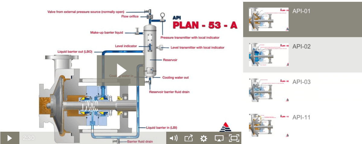
The MP52 series aligns with API 682 Plans 52 and 53A. The Plan 52 is designed to support liquid buffer fluid for a containment seal chamber that is below the seal chamber pressure. The Plan 53A is a pressurized system designed to isolate the seal from the process completely by providing liquid barrier fluid at a pressure higher than the seal chamber.
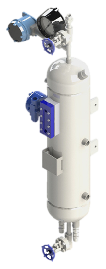
Our seal reservoirs are built to ASME Section VIII standards and are available with ASME U code stamps. Flexaseal Engineered Seals and Systems, LLC provides standard and custom buffer fluid reservoirs that meet API 682 Standards. As an industrial seal pot manufacturer for the chemical, petrochemical, and industrial industries, our seal pot systems help protect the environment and your workers from hazardous materials.

FLUSH PLANS FOR MECHANICAL SEALS – INTRODUCTIONPumps and seals are being installed into increasingly difficult services. Forsuccessful operation of mechanical seals, the environment and care of the sealsrequire more sophisticated seal chambers and flushing arrangements. This sectionof the Dean Pump Price Book is designed to allow the application and pricing offlush plans suitable to meet the requirements for the mechanical seal.The American Petroleum Institute (API) has defined certain seal flusharrangements known by their plan numbers. Later, the flush plans developed forthe ANSI standard followed suit and placed the digits "73" in front of the API plannumber to achieve some standardization within the process industry. Thus, APIplan 11 becomes and ANSI Plan 7311.Dean Pump has worked with many engineering houses and customers over theyears and has developed a great deal of experience with sealing systems. WhileDean will quote any flush system requirement as requested by a particularcustomer, it has been found that the API/ANSI systems generally meet or exceedmost customer requirements. In addition, Dean Pump developed the Seal GuardEnvironment systems that provide the ultimate mechanical seal flush plan. Forsystems that do not require ANSI/API flush plans, Dean Pump has also includedthe P1200 loop, which is a basic low cost flush plan to satisfy the economyminded customer.The experience of Dean Pump is contained in these price pages. Many of theflush plans are divided into "Toxic/Flammable" and "Non-Toxic/Non-Flammable“services. The information on these plans along with the details described in the"Special Notes" section can be used as a guide in quoting and discussing optionswith customers. The "fine print" in the Special Notes section provides a multitude ofdetails about each flush system. For example, a customer requesting all socketwelded connections can not have every connection welded. Some accommodationmust be made for disconnecting the system. Being aware of the requirements ofthe customer and the manufacturing limitations of the product is extremely helpful.API flush plans are based on the 7 th Edition of API610. Newer versions of the APIspecifications has limited the cooling and flushing options available.Finally, if there are any doubts, questions, or comments, please feel free to call theFactory and the seal vendor.Effective: FEBRUARY 2011 • Replaces: NEWPage 1
SEAL GUARD SYSTEMS – PRODUCT DESCRIPTIONSeal Guard systems are designed to provide a clean liquid for seal flushing thatprovides protection for the mechanical seal in the pump seal chamber. Dean Pumpoffers two basic systems to guard against mechanical seal failure. These systemswill also help to prolong the life of the seal. Both systems are filtration systemsinstalled into the seal flush lines to remove stray abrasive particles which causeseal face wear.Seal Guard A - is designed for filtration only. Particles larger than 10 microns arefiltered from the system using clean-able or replaceable 316SS woven filterelements.Seal Guard B - is designed for high temperature applications and includes a heatexchanger installed ahead of the replaceable filter elements for both filtration andtemperature control.Seal Guard systems are most often used with MIN-FLO Bushings in the pump sealchamber. These bushings restrict the flow from the seal chamber back into thepump during operation and increases the effectiveness of the Seal Guard system.Seal Guards can be used on any pump product line. Their sale is not limited toDean Pump products. Seal Guards are hydrostatically tested but do not meet anyindustrial standard and are not for application to API610 series pumps. Seal Guardapplications must be limited to iron or steel pumps and are not suitable forapplications that require alloy materials.The Seal Guard system is fully described in Bulletin A2000.Effective: FEBRUARY 2011 • Replaces: NEWPage 2
SEAL GUARD SYSTEMS – (See Note #1)Model A Series – Filtration Only (See Note #2)Mounted on Pump BaseplateModel Description List PriceA500T A Series Seal Guard - Filtration - Threaded Connections $4,483A500F A Series Seal Guard - Filtration - Flanged Connections C/FA700T A Series Seal Guard - Filtration - Threaded Connections C/FBD500TB500TModel B Series – Filtration and Cooling (See Notes #2 & #3)Mounted on Separate BaseplateModel Description List PriceBD200T B Series Seal Guard - Cooling & Filtration - $5,248Threaded Connections & Duplex FilterB400T B Series Seal Guard - Cooling & Filtration - $5,248Threaded Connections & Simplex FilterB400F B Series Seal Guard - Cooling & Filtration - C/FFlanged Connections & Simplex FilterB500T B Series Seal Guard - Cooling & Filtration - $6,226Threaded Connections & Simplex FilterBD500T B Series Seal Guard - Cooling & Filtration - $8,240Threaded Connections & Duplex FilterNotes:1. Seal Guard systems are not rated for API application and are suitable for pumps in steel or iron construction only. Do notuse for 316SS or other alloy applications.2. The product description letters and numbers are as follows:First Letter - Seal Guard Series A - Filtration Only; B - Cooling and Filtration. (The letter D following in the second positionindicates a Duplex arrangement.); 3 Digit Number indicates the pressure rating of the Seal Guard system in psi.;Final Letter: T - Threaded Construction; F - Flanged Construction3. The heat exchangers provided for Seal Guard B are furnished with a steel shell and 316SS tube as standard.Effective: FEBRUARY 2011 • Replaces: NEWPage 3
DEAN P1200 ECONOMY FLUSH PLAN FOR PROCESS PUMPSPlan Description:Dean Plan P1200 systems include piping (or tubing) from the pumpdischarge gauge connection to the seal flush connection on the pumpbackhead or seal gland. These plans include all piping and/or tubing.List Prices (Notes 1 & 3)Carbon SteelCarbon SteelFitted 316SS Pipe 316SS PipeSystem Description (Note #2) Tubing Threaded ThreadedRecirculation of Pumpage from Pump Case toP1200 Seal Without Orifice (Similar to API Plan 11 orANSI Plan 7311) VALVE NOT INCLUDED$216 $329 $456 $692Valve Valve for Recirculation Line $205 $762 $205 $762General Notes:1. For all other flush plans, refer to API/ANSI Flush Plans shown elsewhere for your particular requirements.2. The plan with carbon steel tubing uses carbon steel fittings with 316SS tubing.3. Connections on the casing require a price adder for discharge gauge connections and may require an additional price adderif the seal chamber requires back drilling.Effective: FEBRUARY 2011 • Replaces: NEWPage 4
SOME COMMENTS AND RECOMMENDATIONSABOUT API/ANSI FLUSH PLANSThere are two organizations in the United States which have taken the lead in developingacceptable standards for the pump industry. The American Petroleum Institute (API) and AmericanNational Standards Institute (ANSI) have outlined a number of flush plans which encompass themajority of applications. API610 is mainly recognized as a standard which defines the qualityrequirements of a pump and/or system. ANSI-B73.1 is viewed as more of a dimensional and featurestandard. ANSI plans are designated the same as API plans except for the addition of a "73" prefixon the plan number. For example, an API Plan 21 is designated as an ANSI Plan 7321.API and ANSI flush plans are similar and upon initial examination look nearly identical. However,there are definite differences in their construction. Often, API flush plans, which are historicallylocated in refinery environments, are piped and welded. ANSI plans, on the other hand, can utilizetubing. Another notable difference is in the API plan 52/53 and the ANSI plan 7352/7353. APIspecifies Schedule 40 minimum thickness vessels. ANSI allows for the use Schedule 10 vessels. Allof the plans are offered in steel and stainless steel construction. They also have differingconstructions for Toxic/Flammable or Nontoxic/Nonflammable applications.Meeting the customer"s specific requirements is the most important consideration in applying theseplans. Many customers modify their individual requirements from the API and ANSI specifications.Sometimes these are more stringent rules than the API and ANSI specifications. These must takeprecedence over the standard flush plans. There are some limitations as to what the flush plans canor cannot accomplish. The Special Application Notes section on each sheet identifies the particularlimitations of each of the flush plans. For example, a flush loop which requires socket welded jointscan not have all the connections welded some provision must be made to allow for disassembly andrepair.When applying a particular flush plan to a specific job, great care should be taken to insure theneeds of the customer are met. Do not select a plan based solely upon pricing. In general, most APIplans require piping and many require welded joints. Note that these are the most expensive plans.A few API services permit the less expensive plans but, the customer"s requirements takeprecedence. ANSI, on the other hand, is much less specific but still requires close analysis of thecustomer"s specifications and requirements for guidance. However, API plans are often seen onANSI type pumps. Oil companies are very likely to request the more expensive plan and will pay forit. Do not make errors in this area. If there is any doubt, or questions regarding plan selection, sendthe specification/ requirements to the factory for review. The factory will provide any comments,limitations, and pricing that is required.Effective: FEBRUARY 2011 • Replaces: NEWPage 5
API PLAN 11 - FLUSH PLAN FOR PROCESS PUMPS (Note #1)ANSI PLAN 7311 – FLUSH PLAN FOR CHEMICAL PUMPSPlan Description:API Plan 11 (ANSI Plan 7311) systems include piping (ortubing) from the pump discharge gauge connection throughan orifice to the seal flush connection on the pumpbackhead or seal gland. These plans include all piping,tubing, and the orifice. Refer to Note #B for additionalpump drilling.SYSTEMS FOR NON-TOXIC AND NON-FLAMMABLE APPLICATIONSSystem DescriptionDescription Special Notes Max. Press. Max. Temp. List PriceAASteel Threaded Pipe and Fittings with 316SS Tubingand Tube Connectors2, 3, 7, 19 500psi 800º F. $ 413AB Steel Threaded Pipe and Fittings 2, 5, 8 500psi 800º F. $ 627AC316SS Threaded Pipe and Fittings with 316SS Tubing andTube Connectors2, 3, 7, 19 500psi 850º F. $ 483AD All 316SS Threaded Pipe and Fittings 2, 5, 8, 500psi 850º F. $1,496SYSTEMS FOR TOXIC AND/OR FLAMMABLE APPLICATIONSSystem Description Special Notes Max. Press. Max. Temp. List PriceAESocket Welded Steel Pipe and Fittings with 316SS Tubingand Tube Connectors1, 4, 7, 19 500psi 300º F. $ 890AF Socket Welded Steel Pipe and Fittings 1, 6, 8 500psi 800º F. $1,124AGSocket Welded 316SS Pipe and Fittings with 316SS Tubingand Tube Connectors2, 3, 7, 19 500psi 300º F. $ 982AH All Socket Welded 316SS Pipe and Pipe Fittings 2, 5, 8 500psi 850º F. $1,577General Notes:A. ALL PUMPS - The plans are similar to but may not comply with API610, 5 th Ed. Review customer requirements as plansmay not comply with later editions or specific customer requirements.B. ALL PUMPS - Flush plans require one or more pump taps. Add the price of the discharge and suction gauge connections ifrequired. For clamped seat applications, consult factory.Special Application Notes:1. Pipe connections at the pump are threaded and are not backwelded.2. All pipe joints are threaded.3. Pipe nipples, threaded pipe fittings, stainless steel tubing, and compression type stainless steel tube connectors.4. Pipe, pipe nipples, socket weld pipe fittings, backwelded threaded pipe fittings, stainless steel tubing and compression typestainless steel tube connectors with threaded pipe connections that are not backwelded.5. Pipe nipples, threaded pipe fittings, and threaded pipe unions.6. Pipe, pipe nipples, socket weld pipe fittings, backwelded threaded pipe fittings, socket weld pipe unions.Effective: FEBRUARY 2011 • Replaces: NEWPage 7
API PLAN 12 - FLUSH PLAN FOR PROCESS PUMPS (General Note #A)ANSI PLAN 7312 – FLUSH PLAN FOR CHEMICAL PUMPSPlan Description:API Plan 12 (ANSI Plan 7312) systems include piping (ortubing) from the pump discharge gauge connection througha Y-strainer, and orifice to the seal flush connection on thepump backhead or seal gland. These plans include allpiping, tubing, and the orifice. Refer to Note #B foradditional pump drilling.SYSTEMS FOR NON-TOXIC AND NON-FLAMMABLE APPLICATIONSSystem DescriptionDescription Special Notes Max. Press. Max. Temp. List PriceBASteel Threaded Pipe and Fittings with 316SS Tubing andTube Connectors and Y-Strainer2, 3, 7, 9, 19 500psi 800º F. $ 638BB Steel Threaded Pipe and Fittings 2, 5, 8, 9 500psi 800º F. $1,123BC316SS Threaded Pipe and Fittings with 316SS Tubing andTube Connectors and Y-Strainer2, 3, 7, 9, 19 500psi 850º F. $ 939BD All 316SS Threaded Pipe and Fittings and Y-Strainer 2, 5, 8, 9 500psi 850º F. $1,736SYSTEMS FOR TOXIC AND/OR FLAMMABLE APPLICATIONSSystem Description Special Notes Max. Press. Max. Temp. List PriceBESocket Welded Steel Pipe and Fittings with 316SS Tubingand Tube Connectors and Y-Strainer1, 4, 7, 10, 19 500psi 300º F. $1,298BF Socket Welded Steel Pipe and Fittings and Y-Strainer 1, 6, 8, 10 500psi 800º F. $1,602BGSocket Welded 316SS Pipe and Fittings with 316SS Tubingand Tube Connectors and Y-Strainer2, 3, 7, 9, 19 500psi 300º F. $1,270BHAll Socket Welded 316SS Pipe and Pipe Fittings andY-Strainer2, 5, 8, 9 500psi 850º F. $1,817General Notes:A. ALL PUMPS - The plans are similar to but may not comply with API610, 5 th Ed. Review customer requirements as plansmay not comply with later editions or specific customer requirements.B. ALL PUMPS - Flush plans require one or more pump taps. Add the price of the discharge and suction gauge connections ifrequired. For clamped seat applications, consult factory.Special Application Notes:1. Pipe connections at the pump are threaded and are not backwelded.2. All pipe joints are threaded.3. Pipe nipples, threaded pipe fittings, stainless steel tubing, and compression type stainless steel tube connectors.4. Pipe, pipe nipples, socket weld pipe fittings, backwelded threaded pipe fittings, stainless steel tubing and compression type stainless steeltube connectors with threaded pipe connections that are not backwelded.5. Pipe nipples, threaded pipe fittings, and threaded pipe unions.6. Pipe, pipe nipples, socket weld pipe fittings, backwelded threaded pipe fittings, socket weld pipe unions.7. Stainless steel orifice plate in tube connector.8. Stainless steel orifice plate in pipe union.9. Y-strainer has stainless steel screen and 1/4" NPT (plugged) blow-off connection.10. Y-strainer has stainless steel screen and bolted cap without blow-off connection.19. This loop has stainless steel tubing and should not be used where chlorides are present.Effective: FEBRUARY 2011 • Replaces: NEWPage 8
API PLAN 21 - FLUSH PLAN FOR PROCESS PUMPS (General Note #A)ANSI PLAN 7321 – FLUSH PLAN FOR CHEMICAL PUMPSWHEN SPECIFIEDPlan Description:API Plan 21 (ANSI Plan 7321) systems include piping (ortubing) from the pump discharge gauge connection throughthe heat exchanger to the seal flush connection on thepump backhead or seal gland. These plans include allpiping, tubing, heat exchanger, and the orifice. The heatexchanger includes a steel shell and 316SS tubing. Ref.Note #B.SYSTEMS FOR NON-TOXIC AND NON-FLAMMABLE APPLICATIONSMAWP 500psi @System Description Special Notes 300º F 650º F 750º FCACBCCCDSteel Threaded Pipe and Fittings with 316SS Tubing andSteel Threaded Pipe and Fittings and Heat Exchanger316SS Threaded Pipe and Fittings with 316SS Tubing andAll 316SS Threaded Pipe and Fittings and Heat Exchanger2, 3, 7, 11, 13,2, 5, 8, 11, 13,2, 3, 7, 11, 13,2, 5, 8, 11, 13,Heat Exchanger (Steel Sheel & 316SS Tubing)(Steel Sheel & 316SS Tubing)Heat Exchanger (Steel Sheel & 316SS Tubing)(Steel Sheel & 316SS Tubing)19, 212119, 2121$3,301$3,663$5,016$5,229$3,301$3,663.$5,489$5,701$4,864$5,227$6,700$6,913ADD Temperature Indicator 13 C/F C/F C/FSYSTEMS FOR TOXIC AND/OR FLAMMABLE APPLICATIONSSystem Description Special Notes 300º FMAWP 500psi @650º F 750º FCESocket Welded Steel Pipe and Fittings and Heat Exchanger 1, 6, 8, 11, 12,(Steel Sheel & 316SS Tubing) 14, 21$4,286 $4,286 $5,849CFAll 316SS 316SS Pipe and Fittings and Heat Exchanger 2, 5, 8, 11, 13, C/F C/F C/F(Steel Sheel & 316SS Tubing) 21ADD Temperature Indicator with Thermowell 14 C/F C/F C/FGeneral Notes:A. ALL PUMPS - The plans are similar to but may not comply with API610, 5 th Ed. Review customer requirements as plans may not comply withlater editions or specific customer requirements.B. ALL PUMPS - Flush plans require one or more pump taps. Add the price of the discharge and suction gauge connections if required. Forclamped seat applications, consult factory.Special Application Notes:1. Pipe connections at the pump are threaded and are not backwelded.2. All pipe joints are threaded.3. Pipe nipples, threaded pipe fittings, stainless steel tubing, and compression type stainless steel tube connectors.4. Pipe, pipe nipples, socket weld pipe fittings, backwelded threaded pipe fittings, stainless steel tubing and compression type stainless steeltube connectors with threaded pipe connections that are not backwelded.5. Pipe nipples, threaded pipe fittings, and threaded pipe unions.6. Pipe, pipe nipples, socket weld pipe fittings, backwelded threaded pipe fittings, socket weld pipe unions.7. Stainless steel orifice plate in tube connector.8. Stainless steel orifice plate in pipe union.11. Heat exchanger has 1/4" diameter, 18 gauge, stainless steel tubes good for the maximum operating temperature and pressure of the pump.12. Heat exchanger connections are threaded and are not backwelded to allow replacement of the tube coil.13. Dial thermometer is 3" diameter, bi-metal, and screwed into pipe TEE and is furnished only when specified.14. Dial thermometer is 3" diameter, bi-metal, and screwed into a thermometer socket which is welded into pipe TEE and is furnished onlywhen specified.19. This loop has stainless steel tubing and should not be used where chlorides are present.Effective: FEBRUARY 2011 • Replaces: NEWPage 9
API PLAN 22 - FLUSH PLAN FOR PROCESS PUMPS (General Note #A)ANSI PLAN 7322 – FLUSH PLAN FOR CHEMICAL PUMPSWHEN SPECIFIEDPlan Description:API Plan 22 (ANSI Plan 7322) systems include piping (ortubing) from the pump discharge gauge connection througha Y-strainer, through the heat exchanger to the seal flushconnection on the pump backhead or seal gland. Theseplans include all piping, tubing, heat exchanger, and theorifice. The heat exchanger includes a steel shell and316SS tubing. Ref. Note #19.SYSTEMS FOR NON-TOXIC AND NON-FLAMMABLE APPLICATIONSMAWP 500psi @System Description Special Notes 300º F 650º F 750º FDADBDCDDSteel Threaded Pipe and Fittings with 316SS Tubing andSteel Threaded Pipe and Fittings and Heat Exchanger316SS Threaded Pipe and Fittings with 316SS Tubing andAll 316SS Threaded Pipe and Fittings and Heat Exchanger2, 3, 7, 9, 11, 13,2, 5, 8, 9, 11, 13,2, 3, 7, 9, 11, 13,2, 5, 8, 9, 11, 13,Heat Exchanger (Steel Sheel & 316SS Tubing) and Y-Strainer(Steel Sheel & 316SS Tubing) and Y-StrainerHeat Exchanger (Steel Sheel & 316SS Tubing) and Y-Strainer(Steel Sheel & 316SS Tubing) and Y-Strainer19, 212119, 2121$3,549$3,912$5,454$5,460$3,549$3,912$5,928$5,955$5,112$5,475$7,138$7,145ADD Temperature Indicator with Thermowell 14 C/F C/F C/FSYSTEMS FOR TOXIC AND/OR FLAMMABLE APPLICATIONSMAWP 500psi @System Description Special Notes 300º F 650º F 750º FDEDFSocket Welded Steel Pipe and Fittings and Heat ExchangerAll 316SS 316SS Pipe and Fittings and Heat Exchanger1, 6, 8, 10, 11,2, 5, 8, 9, 11, 13,(Steel Sheel & 316SS Tubing) and Y-Strainer(Steel Sheel & 316SS Tubing) and Y-Strainer12, 14, 2121$4,534C/F$4,534C/F$6,097C/FADD Temperature Indicator with Thermowell 14 C/F C/F C/FGeneral Notes:A. ALL PUMPS - The plans are similar to but may not comply with API610, 5 th Ed. Review customer requirements as plans may not comply withlater editions or specific customer requirements.B. ALL PUMPS - Flush plans require one or more pump taps. Add the price of the discharge and suction gauge connections if required. Forclamped seat applications, consult factory.Special Application Notes:1. Pipe connections at the pump are threaded and are not backwelded.2. All pipe joints are threaded.3. Pipe nipples, threaded pipe fittings, stainless steel tubing, and compression type stainless steel tube connectors.4. Pipe, pipe nipples, socket weld pipe fittings, backwelded threaded pipe fittings, stainless steel tubing and compression type stainless steeltube connectors with threaded pipe connections that are not backwelded.5. Pipe nipples, threaded pipe fittings, and threaded pipe unions.6. Pipe, pipe nipples, socket weld pipe fittings, backwelded threaded pipe fittings, socket weld pipe unions.7. Stainless steel orifice plate in tube connector.8. Stainless steel orifice plate in pipe union.9. Y-strainer has stainless steel screen and 1/4" NPT (plugged) blow-off connection.10. Y-strainer has stainless steel screen and bolted cap without blow-off connection.11. Heat exchanger has 1/4" diameter, 18 gauge, stainless steel tubes good for the maximum operating temperature and pressure of the pump.12. Heat exchanger connections are threaded and are not backwelded to allow replacement of the tube coil.13. Dial thermometer is 3" diameter, bi-metal, and screwed into pipe TEE and is furnished only when specified.14. Dial thermometer is 3" diameter, bi-metal, and screwed into a thermometer socket which is welded into pipe TEE and is furnished onlywhen specified.19. This loop has stainless steel tubing and should not be used where chlorides are present.21. Heat exchanger size may vary from standard offering due to service conditions of liquid being pumped.Effective: FEBRUARY 2011 • Replaces: NEWPage 10
API PLAN 23 - FLUSH PLAN FOR PROCESS PUMPS (General Note #A)ANSI PLAN 7323 – FLUSH PLAN FOR CHEMICAL PUMPSWHEN SPECIFIEDPlan Description:API Plan 23 (ANSI Plan 7323) systems include piping (ortubing) from the seal flush connection on the backhead orseal gland, through the heat exchanger, and back to theseal gland. These plans include all piping, tubing, heatexchanger, and the orifice. The heat exchanger includes asteel shell and 316SS tuning. Ref. Note #B. – Similar toPlan 21 (7321) with addition of Pumping Ring in sealchamber and may require additional pump changes.SYSTEMS FOR NON-TOXIC AND NON-FLAMMABLE APPLICATIONSMAWP 500psi @System Description Special Notes 300º F 650º F 750º FEASteel Threaded Pipe and Fittings with 316SS Tubing and 2, 3, 11, 13, 19,Heat Exchanger (Steel Sheel & 316SS Tubing) and Y-Strainer 21C/F C/F C/FEBSteel Threaded Pipe and Fittings and Heat Exchanger(Steel Sheel & 316SS Tubing) and Y-Strainer2, 5, 11, 13, 21 C/F C/F C/FEC316SS Threaded Pipe and Fittings with 316SS Tubing and 2, 3, 11, 13, 19,Heat Exchanger (Steel Sheel & 316SS Tubing) and Y-Strainer 21C/F C/F C/FEDAll 316SS Threaded Pipe and Fittings and Heat Exchanger(Steel Sheel & 316SS Tubing) and Y-Strainer2, 5, 11, 13, 21 C/F C/F C/FADD Temperature Indicator 13 C/F C/F C/FSYSTEMS FOR TOXIC AND/OR FLAMMABLE APPLICATIONSMAWP 500psi @System Description Special Notes 300º F 650º F 750º FSocket Welded Steel Pipe and Fittings and Heat Exchanger 1, 6, 11, 12, 14,EEC/F C/F C/F(Steel Sheel & 316SS Tubing) and Y-Strainer 21All 316SS 316SS Pipe and Fittings and Heat ExchangerC/FEF2, 5, 11, 13, 21 C/FC/F(Steel Sheel & 316SS Tubing) and Y-StrainerADD Temperature Indicator with Thermowell 14 C/F C/F C/FGeneral Notes:A. ALL PUMPS - The plans are similar to but may not comply with API610, 5 th Ed. Review customer requirements as plans may not comply withlater editions or specific customer requirements.B. ALL PUMPS - Flush plans require one or more pump taps. Add the price of the discharge and suction gauge connections if required. Forclamped seat applications, consult factory.Special Application Notes:1. Pipe connections at the pump are threaded and are not backwelded.2. All pipe joints are threaded.3. Pipe nipples, threaded pipe fittings, stainless steel tubing, and compression type stainless steel tube connectors.5. Pipe nipples, threaded pipe fittings, and threaded pipe unions.6. Pipe, pipe nipples, socket weld pipe fittings, backwelded threaded pipe fittings, socket weld pipe unions.11. Heat exchanger has 1/4" diameter, 18 gauge, stainless steel tubes good for the maximum operating temperature and pressure of the pump.13. Dial thermometer is 3" diameter, bi-metal, and screwed into pipe TEE and is furnished only when specified.14. Dial thermometer is 3" diameter, bi-metal, and screwed into a thermometer socket which is welded into pipe TEE and is furnished onlywhen specified.19. This loop has stainless steel tubing and should not be used where chlorides are present.21. Heat exchanger size may vary from standard offering due to service conditions of liquid being pumped.All Requests for Plan 23/73223 Must Be Made to the Application EngineersEffective: FEBRUARY 2011 • Replaces: NEWPage 11
API PLAN 31 - FLUSH PLAN FOR PROCESS PUMPS (Note #1)ANSI PLAN 7331 – FLUSH PLAN FOR CHEMICAL PUMPSPlan Description:API Plan 31 (ANSI Plan 7331) systems include piping (ortubing) from the pump discharge gauge connection througha cyclone separator to the seal flush connection on thepump backhead or seal gland and fluid with solids back topump suction gauge connection. These plans include allpiping, tubing, and the cyclone separator. Refer to Note #Band #C for preparation. See note #D for performance.SYSTEMS FOR NON-TOXIC AND NON-FLAMMABLE APPLICATIONSSystem DescriptionDescription Special Notes Max. Press. Max. Temp. List PriceFASteel Threaded Pipe and Fittings with 316SS Tubing andTube Connectors2, 3, 7, 19 500psi 800º F. C/FFB Steel Threaded Pipe and Fittings 2, 5, 8 500psi 800º F. C/FFC316SS Threaded Pipe and Fittings with 316SS Tubing andTube Connectors2, 3, 7, 19 500psi 850º F. C/FFD All 316SS Threaded Pipe and Fittings 2, 5, 8, 500psi 850º F. C/FSYSTEMS FOR TOXIC AND/OR FLAMMABLE APPLICATIONSSystem Description Special Notes Max. Press. Max. Temp. List PriceFESocket Welded Steel Pipe and Fittings with 316SS Tubingand Tube Connectors1, 4, 7, 19 500psi 300º F. C/FFF Socket Welded Steel Pipe and Fittings 1, 6, 8 500psi 800º F. C/FFGSocket Welded 316SS Pipe and Fittings with 316SS Tubingand Tube Connectors2, 3, 7, 19 500psi 300º F. C/FFH All Socket Welded 316SS Pipe and Pipe Fittings 2, 5, 8 500psi 850º F. $4,518General Notes:A. ALL PUMPS - The plans are similar to but may not comply with API610, 5 th Ed. Review customer requirements as plansmay not comply with later editions or specific customer requirements.B. All items contain steel or stainless steel tubing and should not be used where chlorides are present. Consult factory forspecial pricing.C. ALL PUMPS - Flush plans require one or more pump taps. Add the price of the discharge and suction gauge connectionsif required.For clamped seat applications, consult factory.D. This plan may cause flow disruption in the suction and will decrease total head and efficiency and increase NPSHR.Special Application Notes:1. Pipe connections at the pump are threaded and are not backwelded.2. All pipe joints are threaded.3. Pipe nipples, threaded pipe fittings, stainless steel tubing, and compression type stainless steel tube connectors.4. Pipe, pipe nipples, socket weld pipe fittings, backwelded threaded pipe fittings, stainless steel tubing and compression typestainless steel tube connectors with threaded pipe connections that are not backwelded.5. Pipe nipples, threaded pipe fittings, and threaded pipe unions.6. Pipe, pipe nipples, socket weld pipe fittings, backwelded threaded pipe fittings, socket weld pipe unions.Effective: FEBRUARY 2011 • Replaces: NEWPage 12
API PLAN 32 - FLUSH PLAN FOR PROCESS PUMPS (Note #1)ANSI PLAN 7332 – FLUSH PLAN FOR CHEMICAL PUMPSPlan Description:API Plan 32 (ANSI Plan 7332) systems provide injection tothe seal from an external clean source provided by thecustomer. These plans include all piping, tubing, Y-strainer,pressure gauge, temperature indicator, and flow regulatingvalve. Refer to Note #A and #B for preparation.SYSTEMS FOR NON-TOXIC AND NON-FLAMMABLE APPLICATIONSSystem Description Special Notes Max. Press. Max. Temp. List PriceGAGBGCGDSteel Threaded Pipe and Fittings with 316SS Tubing and TubeConnectors with Y-Strainer, Pressure Gauge, Temperature Gauge,and Flow Regulating ValveSteel Threaded Pipe and Fittings with Y-Strainer, Pressure Gauge,Temperature Indicator, and Flow Regulating Valve316SS Threaded Pipe and Fittings with 316SS Tubing and TubeConnectors with Y-Strainer, Pressure Gauge, TemperatureIndicator, and Flow Regulating ValveAll 316SS Threaded Pipe and Fittings with Y-Strainer, Pressure,Gauge, Temperature Indicator, and Flow Regulating Valve2, 3, 9,13,19,252, 5, 9, 13, 252, 3, 9,13,19,25800º F.850º F.2, 5, 9, 13, 25 500psi 850º F.SYSTEMS FOR TOXIC AND/OR FLAMMABLE APPLICATIONSSystem Description Special Notes Max. Press. Max. Temp. List PriceGEGFGGSocket Welded Steel Pipe and Fittings with 316SS Tubing and1, 4, 10, 14, 18,Tube Connectors with Y-Strainer, Pressure Gauge, Temperature19,25Indicator, and Flow Regulating ValveSocket Welded 316SS Pipe and Fittings with 316SS Tubing and2, 3, 9, 13,Tube Connectors with Y-Strainer, Pressure Gauge, Temperature19, 25Indicator, and Flow Regulating ValveSocket Welded Steel Pipe and Fittings with Y-Strainer, Pressure 1, 6, 10, 14,Gauge, Temperature Indicator, and Flow Regulating Valve18, 25500psi500psi500psi300º F.800º F.300º F.$2,088$2,381$2,785GHAll Socket Welded 316SS Pipe and Pipe Fittings with Y-Strainer,Pressure Gauge, Temperature Indicator, and Flow Regulating Valve2, 5, 9, 13, 25 500psi 850º F. $3,151500psi500psi 800º F.500psi$1,521$1,664$2,221$2,614General Notes:A. ALL PUMPS - The plans are similar to but may not comply with API610, 5 th Ed. Review customer requirements as plans may not comply withlater editions or specific customer requirements.B. ALL PUMPS - Flush plans require one or more pump taps. Add the price of the discharge and suction gauge connections if required. Forclamped seat applications, consult factory.Special Application Notes:1. Pipe connections at the pump are threaded and are not backwelded.2. All pipe joints are threaded.3. Pipe nipples, threaded pipe fittings, stainless steel tubing, and compression type stainless steel tube connectors.4. Pipe, pipe nipples, socket weld pipe fittings, backwelded threaded pipe fittings, stainless steel tubing and compression type stainless steeltube connectors with threaded pipe connections that are not backwelded.5. Pipe nipples, threaded pipe fittings, and threaded pipe unions.6. Pipe, pipe nipples, socket weld pipe fittings, backwelded threaded pipe fittings, socket weld pipe unions.9. Y-strainer has stainless steel screen and 1/4" NPT (plugged) blow-off connection.10. Y-strainer has stainless steel screen and bolted cap without blow-off connection.13. Dial thermometer is 3" diameter, bi-metal, and screwed into pipe TEE and is furnished only when specified.14. Dial thermometer is 3" diameter, bi-metal, and screwed into a thermometer socket which is welded into pipe TEE and is furnished onlywhen specified.18. Pressure gauge connection is threaded and not backwelded.19. This loop has stainless steel tubing and should not be used where chlorides are present.25. For stuffing box pressures greater than 50psi, consult factory for proper application.Effective: FEBRUARY 2011 • Replaces: NEWPage 13
API PLAN 41 - FLUSH PLAN FOR PROCESS PUMPS (Note #1)ANSI PLAN 7341 – FLUSH PLAN FOR CHEMICAL PUMPSWHEN SPECIFIEDPlan Description:API Plan 41 (ANSI Plan 7341) systems include piping(tubing) from the pump discharge gauge connection,through a cyclone separator and heat exchanger to the sealflush connection on the pump backhead or gland and fluidwith solids back to the pump suction gauge connection.Plan includes piping, tubing, cyclone separator andheat exchanger.SYSTEMS FOR NON-TOXIC AND NON-FLAMMABLE APPLICATIONSSystem Description Special Notes Max. Press. Max. Temp. List PriceHAHBHCHDSteel Threaded Pipe and Fittings with 316SS Tubing and TubeSteel Threaded Pipe and Fittings, Heat Exchanger, and Cyclone316SS Threaded Pipe and Fittings with 316SS Tubing and TubeAll 316SS Threaded Pipe and Fittings, Heat Exchanger, and Cyclone2, 3, 11, 13, 15,2, 5, 11, 13, 15,2, 3, 11, 13, 15,2, 5, 11, 13, 15,Connectors, Heat Exchanger, and Cyclone SeparatorSeparatorConnectors, Heat Exchanger, and Cyclone SeparatorSeparator17, 19, 2117, 2117, 19, 2117, 21500psi500psi500psi500psi800º F.800º F.850º F.850º F.C/FC/FC/FC/FSYSTEMS FOR TOXIC AND/OR FLAMMABLE APPLICATIONSSystem Description Special Notes Max. Press. Max. Temp. List PriceHEHFHGHHSocket Welded Steel Pipe and Fittings with 316SS Tubing and TubeSocket Welded Steel Pipe and Fittings, Heat Exchanger, and CycloneSocket Welded 316SS Pipe and Fittings with 316SS Tubing and TubeAll Socket Welded 316SS Pipe and Pipe Fittings, Heat Exchanger,1, 4, 11, 12, 14,1, 6, 11, 12, 14,2, 3, 11, 13, 15,2, 5, 11, 13, 15,Connectors, Heat Exchanger, and Cyclone SeparatorSeparatorConnectors, Heat Exchanger, and Cyclone Separatorand Cyclone Separator15,16, 17, 19, 2115, 16, 17, 2117, 19, 2117, 21500psi500psi500psi500psi300º F.800º F.300º F.850º F.C/FC/FC/FC/FGeneral Notes:A. ALL PUMPS - The plans are similar to but may not comply with API610, 5 th Ed. Review customer requirements as plans may not comply withlater editions or specific customer requirements.B. All items contain steel or stainless steel tubing and should not be used where chlorides are present. Consult factory for special pricing.C. ALL PUMPS - Flush plans require one or more pump taps. Add the price of the discharge and suction gauge connections if required.For clamped seat applications, consult factory.D. This plan may cause flow disruption in the suction and will decrease total head and efficiency and increase NPSHR.Special Application Notes:1. Pipe connections at the pump are threaded and are not backwelded.2. All pipe joints are threaded.3. Pipe nipples, threaded pipe fittings, stainless steel tubing, and compression type stainless steel tube connectors.4. Pipe, pipe nipples, socket weld pipe fittings, backwelded threaded pipe fittings, stainless steel tubing and compression type stainless steeltube connectors with threaded pipe connections that are not backwelded.5. Pipe nipples, threaded pipe fittings, and threaded pipe unions.6. Pipe, pipe nipples, socket weld pipe fittings, backwelded threaded pipe fittings, socket weld pipe unions.11. Heat exchanger has 1/4" diameter, 18 gauge, stainless steel tubes good for the maximum operating temperature and pressure of the pump.12. Heat exchanger connections are threaded and are not backwelded to allow replacement of the tube coil.13. Dial thermometer is 3" diameter, bi-metal, and screwed into pipe TEE and is furnished only when specified.15. The cyclone separator is stainless steel with threaded connections.16. The cyclone separator connections are not backwelded.17. Piping from the cyclone separator to the suction line must be furnished by the customer since connection into the suction nozzle of the pumpis not available.19. This loop has stainless steel tubing and should not be used where chlorides are present.21. Heat exchanger size may vary from standard offering due to service conditions of liquid being pumped.Effective: FEBRUARY 2011 • Replaces: NEWPage 14
ANSI PLAN 7352/7353 – FLUSH PLAN FOR CHEMICAL PUMPSPlan Description:ANSI Plan 7352 systems use anon-pressurized external fluid reservoirwith forced circulation. Reservoir tank,piping, and tubing supplied.Item Description - Mandatory Items Size/ Type CST 316SSJA2 Gallon$3,298 $6,033Schedule 10 Reservoir with (2) Bull"seye Level Gauges, 3/8" 316SS3 Gallon$3553 $6,387Cooling Coil, Orifice Union, and Pressure Gauge. Steel Stand for4 GallonSeparate Mounting or Baseplate Mounting$4,011 $6,9965 Gallon$4,619 $7,910JB(2) Vent and Drain Valves 1/2" Ball Valve -Threaded$ 724 $2,519Socket Welded $ 814 $3,154Gate Valve -Threaded$ 420 $1,605Socket Welded $ 357 $1,937Optional ItemsJC Level GaugeSteel Tubular Type $ 459 $ 916Welded Pad $ 916 $1,527JDAdd for Threaded or Socket Welded Pipe Fittings for Options JE,Threaded$ 612 $1,069JF, JGSocket Welded $ 297 $ 434JE Multi-Port Block/ Bleed Valve for JF, JG, JH INCLUDEDJFPressure Switch - NEMA 7/9 Enclosure, Explosion Proof, Class 1,SPDT$1,373Group C & D, Division 1 (Note B)DPDT$1,831JG Pressure Switch - NEMA 4 Enclosure (Note B)SPDT$ 764DPDT$ 993JHLevel Switch - Ultrasonic - NEMA 7/9 EnclosureSPDT$1,831Explosion Proof, Class 1, Group C & D, Division 1DPDT$2,288JI Mounting of Flush PlanOn Separate StandNO CHARGEOn Pump BaseplateNO CHARGETesting 150psi Air Check NO CHARGEJJ1-1/2X MAWP Non-Witness$ 4591-1/2X MAWP Witness$1,069SEE NEXT PAGE FOR PLAN 5353 AND NOTES.Effective: FEBRUARY 2011 • Replaces: NEWPage 15
ANSI PLAN 7352/7353 – FLUSH PLAN FOR CHEMICAL PUMPSPlan Description:ANSI Plan 7353 systems use apressurized external fluid reservoir withforced circulation. Reservoir tank, piping,and tubing supplied.ANSI PLAN 7353 – FLUSH PLAN FOR CHEMICAL PUMPS CST 316SSJK Use Same Pricing as Plan 7352 and DEDUCT Orifice Union -$82.00 -$157.00General Notes:A. Maximum Allowable Working Pressure (MAWP) - Schedule 10: CST - 450psig @ 550º F; 316SS - 400psig @ 100º FB. Maximum continuous temperature exposure to electrical components is 250º F. For higher temperature switches, consultthe factory with requirements.C. Plan 7352 is normally used with Tandem mechanical seals. Plan 7353 is normally used with Double mechanical seals.Special Application Notes for All 7352 and 7353 Flush Plans:1. Pipe connections at the pump are threaded and are not backwelded.2. All pipe joints are threaded.3. Pipe nipples, threaded pipe fittings, stainless steel tubing, and compression type stainless steel tube connectors.4. Pipe, pipe nipples, socket weld pipe fittings, backwelded threaded pipe fittings, stainless steel tubing and compression typestainless steel tube connectors with threaded pipe connections that are not backwelded.5. Pipe nipples, threaded pipe fittings, and threaded pipe unions.6. Pipe, pipe nipples, socket weld pipe fittings, backwelded threaded pipe fittings, socket weld pipe unions.Effective: FEBRUARY 2011 • Replaces: NEWPage 16
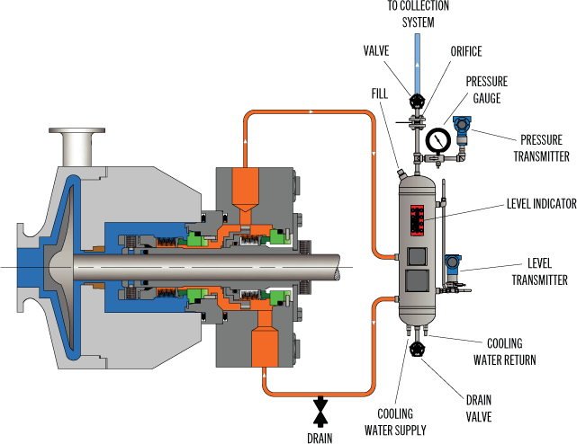
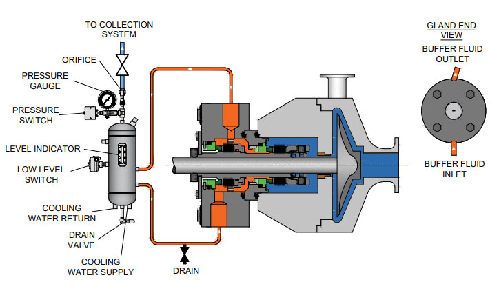
API PLAN 52/53 – FLUSH PLAN FOR PROCESS PUMPSPlan Description:API Plan 52 systems use anon-pressurized external fluid reservoirwith forced circulation. Reservoir tank,piping, and tubing supplied.Item Description - Mandatory Items Size/ Type CST 304SS 316SSSchedule 40 Reservoir with 1/2" NPT Vent and Drain Valves, Welded 2 Gallon $4,286 $7,874 $8,222KAPad Level Gauge, 4-1/2" Pressure Gauge, Multiport Block/ Bleed3 Gallon $4,445 $8,054 $8,422Valve, Orifice Union, 1/2" 316SS Coil with Steel Stand for Mounting 4 Gallon C/F C/F C/Fof Flush Plan or Mounting on Pump Baseplate 5 Gallon C/F C/F C/FKBVent and Drain Gate Valves - Anvil Class 800 or Equivalent perINCLUDEDANSI B16.11 or ANSI B16.5KC Pressure Gauge - Ashcroft Type 1279 or Equivalent INCLUDEDKD Block/ Bleed Valve - Precision General Screw Products or Equiv. INCLUDEDOPTIONAL ITEMSKE Welded Pad Level Gauge with Isolation Valve $ 916 C/F C/FKF Socket Weld Fittings Where Available$ 612 $ 144 $1,069KG Flanged and Socket Weld Fittings Where Available$2,135 $1,201 $3,659KHKIKKPressure Switch - U.E. Electromechanical Products - NEMA 7/9Level Switches - (High or Low) - Ultrasonic - NEMA 7/9 Enclosure,Mounting of Flush PlanSPDTSPDTOn Separate Stand$1,830$1,830NO CHARGEEnclosure, Explosion Proof, Class 1, Group C & D, Division 1Explosion Proof, Class 1, Group C & D, Division 1DPDTDPDTOn Pump Baseplate$1,830$2,288NO CHARGETesting 150psi Air Check NO CHARGEKL1-1/2X MAWP Non-Witness$ 4591-1/2X MAWP Witness$1,069SEE NEXT PAGE FOR PLAN 53 AND NOTES.Effective: FEBRUARY 2011 • Replaces: NEWPage 17
API PLAN 52/53 – FLUSH PLAN FOR PROCESS PUMPSPlan Description:API Plan 53 systems use apressurized external fluid reservoir withforced circulation. Reservoir tank, piping,and tubing supplied.API PLAN 53 – FLUSH PLAN FOR CHEMICAL PUMPS CST 304SS 316SSKM Use Same Pricing as Plan 52 and DEDUCT Orifice Union -$94.00 -$160.00 -$160.00General Notes:A. Maximum Allowable Working Pressure (MAWP) – Schedule 40: CST - 970psig to 625º F; 304SS - 750psig to 300º F;316SS - 825psig to 300º FB. Maximum continuous temperature exposure to electrical components is 250º F. For higher temperature switches, consultthe factory with requirements.C. Plan 52 is normally used with Tandem mechanical seals. Plan 53 is normally used with Double mechanical seals.Special Application Notes for All 52 and 53 Flush Plans:1. Pipe connections at the pump are threaded and are not backwelded.2. All pipe joints are threaded.3. Pipe nipples, threaded pipe fittings, stainless steel tubing, and compression type stainless steel tube connectors.4. Pipe, pipe nipples, socket weld pipe fittings, backwelded threaded pipe fittings, stainless steel tubing and compressiontypestainless steel tube connectors with threaded pipe connections that are not backwelded.5. Pipe nipples, threaded pipe fittings, and threaded pipe unions.6. Pipe, pipe nipples, socket weld pipe fittings, backwelded threaded pipe fittings, socket weld pipe unions.18. Pressure gauge connection is threaded and not backwelded.19. This loop has stainless steel tubing and should not be used where chlorides are present.22. Barrier fluid reservoir is steel construction with 1-1/2 gallon capacity.23. Barrier fluid reservoir is stainless steel construction with 1-1/2 gallon capacity.24. Barrier fluid reservoir connections are threaded and are not backwelded.25. For stuffing box pressures greater than 50psi, consult factory for proper application.Effective: FEBRUARY 2011 • Replaces: NEWPage 18
API PLAN 62 – QUENCH PLAN FOR PROCESS PUMPS (Note #1)ANSI PLAN 7362 – QUENCH PLAN FOR CHEMICAL PUMPSPlan Description:API Plan 62 (ANSI Plan 7362) systems includepiping (tubing) with check valve and blockvalve for external connection to the quenchconnection of the seal gland. Customersupplies steam, gas, water, etc. to quench. Thegland offering must include a quench featureand taps to connect the feature.System Description List PriceLA Steel Threaded Pipe and Fittings $ 984LB 316SS Threaded Pipe and Fittings $2,285General Notes:A. ALL PUMPS - The plans are similar to but may not comply with API610, 5 th Ed. Review customer requirements as plansmay not comply with later editions or specific customer requirements.B. ALL PUMPS - Flush plans require one or more pump taps. Add the price of the discharge and suction gauge connections ifrequired. For clamped seat applications, consult factory.Effective: FEBRUARY 2011 • Replaces: NEWPage 19
API Seal Plan 52 utilizes a reservoir and circulates an unpressurized buffer fluid between the inboard and outboard seals. To provide positive circulation through the support system and into the seal, a pumping ring is employed. Frictional losses in the buffer fluid inlet and outlet lines should be minimized by selecting the proper tube size, using large radius and/or 45 degree bends, and reducing the length of tubing runs. Seal Plan 52 is commonly used with light hydrocarbons or fluids with a high vapor pressure. The buffer fluid must be compatible with process fluid as inboard seal leakage will eventually mix with the buffer fluid.
Plan 52 is available as a seal pot assembly. The associated field installation kit for use in connecting the seal pot assembly to your system is also available. Assembly components may include:
See page 31 of the Mechanical Seal Support Systems Application Guide for additional details and ordering information. Contact your authorized Swagelok sales and service center for information on optional components.
Pumping processes involving hazardous or toxic fluids often utilize dual mechanical seals to ensure operator safety and compliance with environmental regulations. The American Petroleum Institute (API) Standard 682 classifies dual mechanical seals into two categories— pressured and unpressured. For unpressurized configurations, a seal flush system, such as API Plan 52, is required for the seal to operate. A buffer fluid is circulated between the inboard and outboard seals to form a “buffer” between the process fluid and environment.
API Plan 52 seal systems are the most commonly used pressurized dual mechanical seal flush systems in Canadian operations. Plan 52 is widely used in oil and gas operations, but can also be used in chemical and petrochemical refining and power generation applications. Let’s take a look into how the API Plan 52 seal system works for centrifugal pumps and applications in oil and gas, chemical and petrochemical refinement, and power generation.
API Plan 52 seal systems employ a seal pot (reservoir) to deliver an unpressurized buffer fluid to the seal chamber and circulate the fluid between the inboard and outboard mechanical seals. A pumping ring is utilized to provide positive circulation through the seal flush system and into the seal. This plan is commonly used with light hydrocarbons or fluids with a high vapour pressure.
In the event of an inboard seal failure, process fluid will leak into the seal chamber, mixing with the buffer fluid. Thus, the selected buffer fluid must be compatible with the process fluid. One challenge with this plan is frictional losses in the buffer fluid inlet and outlet lines. Frictional losses may be minimized through properly selecting tube size, using large radius and/or 45-degree bends, and reducing the length of tubing in the design.
Tubing configuration and geometry, materials of construction, buffer fluid type, and seal pot volume can be determined and configured based on specific pumping and mechanical seal requirements. API Plan 52 seal systems can include cooling coils within the reservoir to maintain the temperature of buffer fluid being delivered to the seal chamber. This plan can also include instrumentation, such as pressure transmitters, level transmitters, and thermometers depending on the given application. Fluid systems vendors should be consulted to determine configuration specifics such as those listed above.
Depending on the application of dual mechanical seal flush systems, there may be benefits in the higher standards of an ASME stamped seal pot as opposed to a seal pot that meets a lower piping standard. ASME stamped vessels can be more easily tracked and maintained through their Canadian Registration Number (CRN).
In oil and gas operations, including steam-assisted gravity drainage (SAGD), API plan 52 can be used for dual mechanical seals for centrifugal pumps in upstream, midstream, and downstream operations with either high vapour pressure or lower vapour pressure fluids. In chemical plants and petrochemical refineries, dual mechanical seals may be used for high vapour pressure fluid applications. For chemical plants where chemicals are extremely hazardous, a more robust sealing system may be implemented. For power generation, API Plan 52 may be used for water pumping applications, such as boiler feedwater pumps and water treatment pumps.
Whether you are looking to implement a new custom-configured API Plan 52 seal system—or you are looking to upgrade your current plan—Field Advisors at Edmonton Valve & Fitting can provide expert consultations to determine how to increase pumping reliability and efficiency. We are well-versed in local pumping applications for industries including oil and gas, chemical and petrochemical refining, and power generation. We also offer ASME stamped seal pots for customers who would like to ensure proper testing and maintenance tracking with a CRN.
To find out more about how Edmonton Valve & Fittingcan provide API Plan 52 seal systems equipped with ASME stamped seal pots, contact our team of advisorsthrough our website or by calling 780-437-0640.

Process sideSeal chamber cooling or heating and neck bush are necessary, unless otherwise specified. Dead end seal chamber with no circulation. Plugged connections for possible future circulation and quench.
Most common Plans and Sealing SystemsBetween sealsUsed where the pumped product is harmful / hazardous and / or buffer fluid may not contaminate the product. External reservoir at pressure below seal chamber pressure providing buffer liquid forced circulation.
Applicable with hydrocarbons, normally used in conjunction with plan 75 or plan 76. Externally supplied gas buffer (pressure lower than seal pressure). Buffer gas used to dilute seal leakage.
For general applications. Product pumped clean, good lubricating properties and heat removal from the mechanical seal. Recirculation from pump discharge through flow control orifice to the seal.
Used for hot applications or where products have low pressure and are harmful/hazardous. External reservoir pressurized above seal chamber pressure providing barrier fluid to mechanical seals. Forced circulation.
Used where the seal chamber pressure is at discharge pressure (mainly vertical pumps). Recirculation from pump seal chamber through a flow control orifice and back to the seal.
Used for hot liquid applications or where the temperature and pressure in the seal chamber is close to the vapour curve of the product. Recirculation by means of a pumping ring in seal chamber through a cooler and back to seal chamber.
API plan functions Leakage alarm and collection Buffer systems (psealchamb > pbetweenseals) Barrier systems (psealchamb < pbetweenseals) Flushing and cooling Media characteristics Suspended solids Poor lubrication High temperature Hazardous / harmful Leakage may form solids Close to vapourisation point* Only in combination with additional API plan
Used in applications with suspended solids where the SG of the particles are 2x that of the liquid. Recirculation from pump discharge through a cyclone separator, clean fluid to seal chamber, contaminated fluid to suction.
Used when the product being pumped does not have good lubrication properties, is dirty or hazardous. Flush injecton of clean fluid into the seal chamber from an external source.
The API 682 has emerged to become a worldwide accepted standard in today`s refinery and hydrocarbon related applications. EagleBurgmann offers a wide range of high quality mechanical seals and supply systems which fully comply with API 682. From expert consulting and engineering up to modular TotalSealCare service solutions for entire plants EagleBurgmann is your reliable partner for sealing technology. Please ask also for our detailed brochure 58E, our API 682 seal selection software on CD or find your nearest contact at www.eagleburgmann.com/worldSee reverse side of this poster for API seal classification.
Used for hot applications or where the temperature and pressure in the seal chamber is close to the vapour curve of the product. Recirculation from pump discharge through a flow control orifice and cooler into the seal chamber.
Used for applications where products have high pressure and are harmful/hazardous. Pressurization by reference line from seal chamber to a piston pressure booster provides pressurized barrier fluid to circulation system. Forced circulation.
Seal ClassificationExamplesCategory 2 Category 3 ISO 13709 / API 610 10th edition -40 C 400 C, 41 bar g (-40 F 750 F, 600 PSI) Rigorous data requirements 1CW-FXContacting Wet - Fi Xed throttle bushing Burgmann H75VN (Type A)F D Q
3CW-FB Contacting Wet - Face-to-Back 3CW-BB Contacting Wet - Back-to-Back 3CW-FF Contacting Wet - Face-to-Face 3NC-BB Non-Contacting - Back-to-Back 3NC-FF Non-Contacting - Face-to-Face 3NC-FB Non-Contacting - Face-to-Back 2CW-CSContacting Wet Containment Seal Burgmann H75VK-CGSH (Type A)F CSV CSD GBI
TypesType A Pusher seal Temperature: -40 176 C (-40 350 F), pressure: 41 bar g (600 PSI) Type B Metal bellows seal with O-rings Temperature: -40 176 C (-40 350 F), pressure: 21 bar g (300 PSI) Type C Metal bellows seal with flexible graphite Temperature: -40 400 C (-40 750 F), pressure: 21 bar g (300 PSI) Type ES Totally Engineered Sealing system for service conditions outside the operating limits of type A, B and C 3CW-FBF
Seal Code according to API 682 3rd editionExample Category 1 = C1 Category 2 = C2 Category 3 = C3 Arrangement 1 = A1 Arrangement 2 = A2 Arrangement 3 = A3 Type A = A Type B = B Type C = C API plans: 02, 11, 13, 21(22), 23, 31, 32, 52, 53A , 53B, 53C, 54, 62, 65, 72, 74, 75, 76 Explanation of example C2A3A1153A > Category 2 seal chamber, operating conditions and data requirements > Double seal with barrier fluid pressure higher than seal chamber pressure > Pusher type seal > API plans 11 + 53A Category C2 Arrangement A3 Type A API plan(s) 1153A
The API 682 has emerged to become a worldwide accepted standard in today`s refinery and hydrocarbon related applications. Werb-Nr. EagleBurgmann offers a wide range of high quality mechanical 2796 2795 seals and supply systems which fully comply with API 682. From expert consulting and engineering up to modular TotalSealCare service solutions for entire plants EagleBurgmann is your reliable partner for sealing technology. Please ask also for our detailed brochure 58E, our API 682 seal selection software on CD or find your nearest contact at www.eagleburgmann.com/worldSee reverse side for most common API plans and sealing systems.

This application is a continuation of application Ser. No. 09/179,506, filed Oct. 27, 1998, now U.S. Pat. No. 6,173,210, entitled APPARATUS AND METHOD FOR SELECTING A MECHANICAL SEAL, now allowed, which in turn is a continuation of application Ser. No. 09/033,194, filed Mar. 2, 1998, entitled APPARATUS AND METHOD FOR SELECTING A MECHANICAL SEAL, now abandoned, which prior applications are incorporated herein by reference.
This invention relates to automated systems for supporting selection of a mechanical seals for equipment. More particularly, the invention relates to automated systems for supporting advertising, selecting, designing, manufacturing and providing post sales service and support for mechanical seals.
Sales and marketing of mechanical seals presently involves several activities including seal selection, design and engineering of a seal, manufacturing, and post sales service and support. This process involves many different people to gather, manipulate, interpret and process a variety of kinds of information, and is not an exact science.
A mechanical seal is a shaft sealing device provided to contain process fluids within equipment such as a pump, mixer or other rotary equipment. Mechanical seals are used in operations of a typical processing plant. Significant industries that use seals include: pulp and paper, chemical processing, petroleum chemical, oil refining, food processing, and power and utilities, among others.
There are generally three types of mechanical seals: component (made of several pieces), cartridge (components unitized for one piece) and split seals. Cartridge seals generally are preferred over component seals for several reasons. First, cartridge seals may be installed without significant training. These seals also may be tested before shipping to ensure sealability. However, conversion from a component seal to a cartridge seal for an application involves a complex process of selection of an appropriate seal design.
Because of the variety of applications for seals, selection of a seal involves considering several factors. For example, seals typically are connected to equipment with a rotary shaft (pumps being the most common) for which there are a large variety of commercially available designs with different ensional profiles. Equipment also may have been modified in the field for several reasons, resulting in a nonstandard dimensional profile. Additional factors are the operating conditions of the equipment, including process fluids and their combinations, and intentional and unintentional changes in the process fluids used in a systems. Aside from selecting a seal that fits the equipment and is suitable for the given operating conditions, costs of the seal and its installation also are factors.
This selection process therefore generally involves highly trained sales engineers with factory support to perform properly the seal selection process. Their training typically includes mechanical and design engineering and chemical engineering. These individuals typically also perform sales, service and support functions. Because of the complexity of the seal selection process, customers tend to be dependent on these sales engineers. This dependency is due to the complexity of part codes for these seals.
The expertise level of a sales engineer is generally dependent on the size of seal manufacturer, years of experience, education and training, resulting in varying competencies. Sales engineers may possess only industry specific expertise, acquired from their experience. Accordingly, without extensive experience, a sales engineer also may be dependent heavily on factory support for assistance in the seal selection process.
Moreover, sales engineers, despite their experience, still may be dependent on factory support because they typically have immediate access to selection information limited to common equipment and process fluids, either in printed or computer-readable text form. Other information, such as application data, engineering data, special pricing and drawings may be available only at the factory, requiring the sales engineer to use factory support to derive seal selections or to interpret the available information and to select a seal. Accurate communication between sales engineers and factory engineers is a critical component of this process.
Depending on the resources available to a manufacturer, which may depend on its size or its number of years in business, factory support may be limited to manually intensive selection methods prone to errors resulting in an informal, unscientific selection process. Even with more sophisticated procedures based on significant amounts of historical information, however, human intervention is generally required for many decisions made between field sales and factory support personnel because of individuals" judgments and perceptions, which may result in inaccurate selections. In particular, a significant amount of human interaction is required to gather, interpret, manipulate and analyze the application data when the sales engineer requires factory support. In particular, the pump and seal dimensions, operating conditions and process fluids affect the selection of materials to obtain maximum seal life. The human interaction involved in current selection methods may result in different recommendations from different individuals, for the same application, of a seal model, optional seal features, materials of construction, seal environmental controls, i.e., piping plans, and various auxiliary devices to be used with the environmental controls. In addition, the likelihood of an error is increased. An error in any stage of the selection process may result in an inaccurate or incomplete sealing solution, which translates into premature seal failure and increased costs.
There are several steps in the seal selection process which typically involve human interaction. One step is identification of the equipment, e.g., a pump or drive motor or other rotary equipment. The methods of identification differ among sales engineers. Example sources of identification information include identification tags on the equipment, maintenance records, engineering records, purchasing records, equipment manufacturer"s records or seal manufacturer"s records. If these sources provide incomplete information proper equipment identification may be impossible. Even if equipment is properly identified, e.g., by make and model, modifications may have been made to the equipment. A failure to identify such modifications results in an erroneous seal selection. As a result, a trained individual measures the equipment to obtain accurate dimensional data. Dimensional data is commonly collected using forms of varying complexity and completeness. Simple forms tend to be incomplete. Complex forms tend to be subject to interpretation by sales engineers and factory engineers. Both kinds of forms result in errors.
A seal model which is dimensionally compatible for the identified equipment then is selected. In order to make this selection, a sales engineer may refer to information available in a reference guide, or if not identified in a reference guide, performs a dimensional analysis. The dimensional analysis may be performed by the sales engineer or by relying upon factory support. When application data is received at the factory, it is reviewed for completeness and accuracy. If the data is not satisfactory, the process is delayed.
After a dimensionally compatible seal model has been selected, the operating conditions are identified by the sales engineer and are analyzed to confirm that the recommended seal is suitable for the process performed by the equipment. This analysis involves evaluating the operating conditions and the process fluids, with respect to a number of aspects of the seal, including, but not limited to: a metallurgy for general corrosion resistance; a face material combination for lubricity of the chemical and/or corrosion or abrasion resistance; and selection of secondary sealing components, i.e., o-ring elastomers for temperature and chemical resistance.
The operation conditions include but are not limited to: shaft speed as related to seal chamber pressure acting on the seal, i.e., pressure/velocity; stuffing box/seal chamber pressure, which is a function different pump internal part designs (impellers); shaft speed; pump discharge pressure at outlet nozzle; pump suction pressure at inlet nozzle; pressure/velocity parameters for different seal designs and face


 8613371530291