
api plan 62 mechanical seal manufacturer
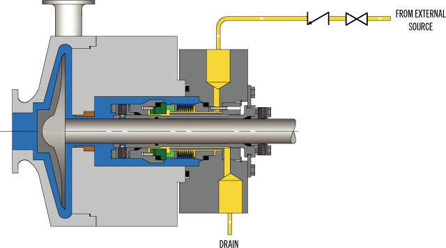
API Plan 62 delivers an external quench fluid to the atmospheric side of the seal. A typical application in a refinery is the prevention of coking on seal faces in hot hydrocarbon service by employing a steam quench. Nitrogen or clean water may also be used to quench or cool and clean the atmospheric side of the seal.
See page 77 of the Mechanical Seal Support Systems Application Guide for additional details and ordering information. Contact your authorized Swagelok sales and service center for information on optional components.

To keep mechanical seal systems functioning as long as possible, we recommend using standardized seal piping plans. Detailed API seal piping plans ensure minimal seal face wear by maintaining the optimal seal chamber environment.
Since they were first formulated, seal piping plans have been maintained and remodeled by the American Petroleum Institute (API). Current plans are based on API 682 and are sorted numerically. In some cases, designated letters are also used to differentiate between plans.
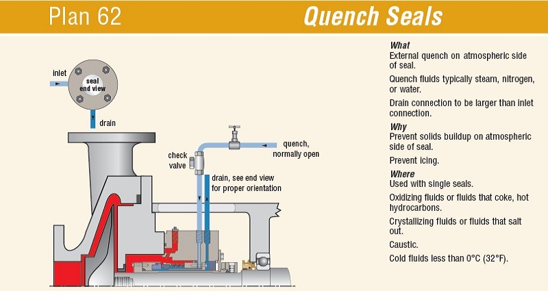
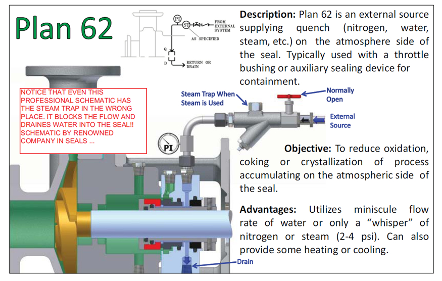
Plan 62 is designed to improve the environment on the atmospheric side of single seals by adding a quench. Typically, this quench is low pressure steam, nitrogen or water to prevent the formation of solids on the atmospheric side of the seal. Plan 62 is typically used with a floating or segmented bushing to limit the leakage of the quench fluid to atmosphere, but can be used with a fixed bushing.
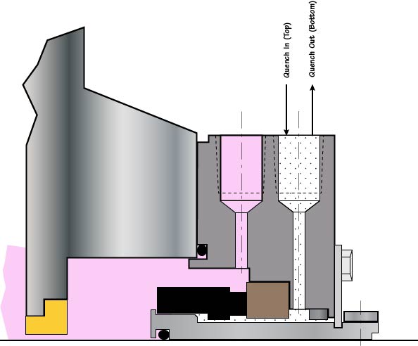
A problem resulting from a steam or water quench is that the bearings (usually immediately near the gland plate) can become contaminated with the quench fluid. This is the reason for providing a close clearance bushing and a drain that is piped away from the seals/bearings.

Plan 62 usually refers to a steam quench on the atmospheric side of the seal. What flush plan is used on the primary seal? What is the seal configuration?
If you have replaced the seal, high resolution close up pictures of the seal surfaces and the condition of the components have an important story to tell. RE: Hot oil circulation pumps Mechanical seal failures API plan 62
Throttle bushing may be worn and have too much clearance allowing too much fluid pressure into primary seal area from pump casing. Check pump shaft run out should not be more than .002". check pump alignment, seals don"t like misalignment no more than .001". Check shaft o-ring on primary seal for correct material composition for temperature range and fluid. Check stuffing box face runout, should be square to shaft no more than .001" Check shaft diameter and shaft condition in o-ring area of seal. Shaft diameter must be in manufactured spec. for o-ring to seal tight. check manufacture specs on these tolerances as mentioned. RE: Hot oil circulation pumps Mechanical seal failures API plan 62
Mechanical seal is a John Crane 604 with a static bellows. Although described as a single mechanical seal, it also has an ECS secondary/backup seal as part of the cartridge (described as dry running), as in the original design a disaster bushing wasn"t considered adequate.
Nature of the failure is external leakage through the outboard ECS (emission control seal). Most recent failure had the ECS seal rings in pieces, but not the only failure observed historically (but I don"t have all the details I"d like).
Plan 62 seal, with N2 as the quench. (There is no flush connection supplied on the gland plate) Also a plan 65A leak detection system on the quench outlet / drain to monitor primary leakage rates.
A problem I"m told we consistently have is blockage of the quench outlet/drain with black oily gunk, such that it can block the quenching flow out the drain. As oil leaks from the primary seal this can backup into the nitrogen feed line (plus leak externally).
Has anybody ever tried using an in-situ cleaning solution to dry and clean up quench outlet lines on a hot oil system??? RE: Hot oil circulation pumps Mechanical seal failures API plan 62
Hot oil pumps I"ve worked on were all fitted with either tandem or double seals, many were modifications of plan 52 ( with pressurised seal fluid reservoir).
Sounds like your hot oil is badly fouled up, and you have excluded high tubeskin temps in the WHRU or the fired heater as a cause in this report. Another reason may be reverse flow of process fluids into hot oil at one or more of the process HXs", most likely at the tube - tubesheet joints- this requires hot oil pressures to be less than process side pressure. Ideally, you"d want hot oil pressure to be higher than process side pressure, else use seal welded tube-tubesheet joints. RE: Hot oil circulation pumps Mechanical seal failures API plan 62
You are totally right!!!,both seals are failed single seal leak through leak detection and ECS leak into external.(Excess leakage flow backs up at orifice and fills leak detector tank,External Leakage = both seals failed) see attached picture.
primary single seal are equipped with quench fluid N2 on atmospheric side plan62 and external drain with leakage detection system plan65A to monitor oil leaking.
"A problem I"m told we consistently have is blockage of the quench outlet/drain with black oily gunk, such that it can block the quenching flow out the drain. As oil leaks from the primary seal this can backup into the nitrogen feed line (plus leak externally)."what we should do to stop and fix this issue???
With a single mechanical the hot oil will go through the seal. Solids in the hot oil will detorioate the seal surfaces and increase the leakage rate. Only real solution there is a pressurized dual seal.
With the single seal you get oil on the other side of the seal. This will have to be removed. I doubt whether Nitrogen is able to do this. Hot steam is to my opinion much better to remove the oil on the outside. You might even have a similar appliance at home for cleaning.
If there is Oxygen in the Nitrogen oxidation processes can be expected causing clogging etc. RE: Hot oil circulation pumps Mechanical seal failures API plan 62
Will using solvent before starting up this Hot Oil Pump, help? We are considering the use of solvent, with specified residence time, before starting up the hot Oil Pump, in order to dislodge the coking debris trapped in the below and loading springs, as well as between the seal faces. We are not intending to use any aggressive solvent, just one which can do some cleaning before starting the pump. RE: Hot oil circulation pumps Mechanical seal failures API plan 62
It is possible that the hot oil is creating Coke at your high temperatures. These Coke particles coat the mechanical seal working parts. The coke particles restrict the movement of the sliding and flexing parts of the seal causing the lapped seal faces to open and leak. The oil must be cooled to stop coking. Sometimes the hot oil will damage bearings in the bearing housing due to the heat from the pump shaft conducted to the bearings and lubricating oil. RE: Hot oil circulation pumps Mechanical seal failures API plan 62
A cool clean oil flush into the seal chamber of the pump with a carbon throat bushing that restricts hot oil dirty oil from entering the seal chamber may help. Maintain the cool seal flushing pressure higher than the stuffing box pressure. RE: Hot oil circulation pumps Mechanical seal failures API plan 62
After more than five years of planning, the American Petroleum Institute (API) is preparing to release the 4th edition of API Standard 682 (ISO 21049:2011). The API 682 standard, which dates back to 1994 and is formally known as Shaft Sealing Systems for Centrifugal and Rotary Pumps, offers specifications and best practices for mechanical seals and systems to pump end users.
The standard’s latest edition began to take shape in 2006, when API formed a 4th edition task force to respond to end users’ questions and comments about previous editions. The task force soon realized that major changes, including reorganization and editing, would be necessary. While addressing every aspect of the resulting 4th edition (which is more than 250 pages long) would be impossible, this article summarizes the standard’s main points.
Those who use API 682 should understand the standard’s scope and remember that the standard does not include specifications for equipment outside that scope, such as engineered seals or mixers. Another important but often misunderstood point is that API 682’s figures are illustrative and not normative in their entirety.
For example, one of API 682’s figures shows a fixed throttle bushing combined with a rotating Type A seal, but seal manufacturers do not always have to combine these two components. The standard provides normative details in clauses and tables to help purchasers distinguish between requirements and suggestions.
The 4th edition continues to divide seals into three categories, three types and three arrangements. For all practical purposes, seal manufacturers can combine a seal’s component parts into nearly any orientation or configuration. Each orientation and configuration has advantages and disadvantages with respect to certain applications, performance and system disturbances.
Before the 4th edition, API 682 did not specify a minimum clearance between the inside diameter of a stationary seal part and the outside diameter of a rotating seal part. The 4th edition specifies this minimum clearance—typically the clearance between the sleeve and the mating ring. The specified clearances are representative of standard clearances that end users have used for decades. End users should not consider seal components to be “shaft catchers” to restrict shaft movement. The minimum clearance specified in API 682 also applies only to equipment within the standard’s scope. Equipment outside that scope, such as non-cartridge seals, older pumps, non-API 610 pumps and certain severe services, might benefit from larger clearances.
The new standard also updates the default bushings for the gland plate for the three seal categories. Fixed throttle bushings are now the default for Category 1 only, while floating bushings are the default for Categories 2 and 3.
While the 4th edition features the recommended seal selection procedure from the standard’s first three editions, it adds an alternative selection method in Annex A. Proposed by task force member Michael Goodrich, this alternative method recommends using material data sheet information to select a sealing arrangement.
Plan 65 is now subdivided into 65A and 65B. End users can use Plan 65A to detect an excessive leakage flow rate and Plan 65B to detect a certain amount of cumulative leakage.
Plans 66A and 66B are new to the standard, although end users have used them previously in pipeline applications. These plans detect and restrict excessive leakage rates in case of an Arrangement 1 seal failure.
The 4th edition now requires Plan 52, 53A, 53B and 53C systems to have a sufficient working volume of buffer or barrier fluid for at least 28 days of operation without refilling. As a point of reference, the default reservoir for Plans 52 and 53A has a three-gallon capacity, or pot, for pump shafts smaller than 2.5 inches and a five-gallon pot for larger shaft sizes. Plan 53C must have the same working volume of fluid as Plan 53A. For Plan 53B, the default bladder and accumulator sizes are five gallons and nine gallons, respectively. The design of Plan 53B systems can be complex, especially when ambient temperatures vary widely, and purchasers should become familiar with the calculations and procedures in the 4th edition’s Annex F tutorial. The new edition also discusses the option of adding a pressure gauge and isolation valve to check the accumulator or bladder’s integrity in a Plan 53B system.
The 4th edition has revised the data sheets in Annex C extensively to make them the same for all seal categories. Only two data sheets are included in the 4th edition—one in metric units and one in U.S. customary units. The new edition also folds Annex J into Annex E.
Previous editions of API 682 required metal plugs and anaerobic sealants when shipping new or repaired cartridges. After much debate, the task force decided that threaded connection points should be protected with plastic plugs for shipment. These plastic plugs should be red and have center tabs that operators can pull easily to distinguish the plugs from metal plugs. Shippers should also attach yellow warning tags to the plugs to indicate that end users need to remove the plugs before operation.
Although tutorial notes are scattered throughout API 682, this edition expands the tutorial section, Annex F, from seven pages to 42 pages. The expanded annex includes illustrative calculations. In particular, users interested in systems such as Plan 53B will find Annex F to be useful.
The 4th edition of API 682 is the product of more than 20 years of discussion, debate, usage and peer review. It includes a strong set of defaults and is by far the best and most logical starting point for mechanical seal and systems use. Equipment operators should take the time to familiarize themselves with API 682 to get the most out of this comprehensive standard.

Seal Support Systems operate to control the fluid in between and around the seal faces whether cleaning, cooling or heating the seal media or providing a separate fluid to the mechanical seal.
Some applications are simply not suitable for mechanical seals e. g applications which are corrosive, abrasive, crystallizing or precipitative. In order for a mechanical seal to operate under these applications with reasonable mean time between failure (MTBF), either the seal fluid requires treatment before coming into contact with the seal faces or an external fluid is required which is compatible with the process. Also double mechanical seals will require some sort of fluid to act as a buffer or barrier fluid andthe system which provides this buffer or barrier fluid are Seal Support Systems.
A seal plan is used in conjunction with the API 682 Standard and it is a way to formalise the different seal support systems into a standard. It consists of seal flush plans, buffer & barrier fluid plans, quench plans and gas supply plans.
The API Plan 53A is a dual seal plan where a barrier fluid is supplied to a double mechanical seal between the 2 sets of faces of the mechanical seal.
Plan 62 is a quench seal plan where a fluid is supplied to the space between the atmospheric side of the mechanical seal and the throttle bushing on the shaft.
Flowserve provides Seal Support Systems for in accordance with API 682 but can also provide systems outside of this standard, if the application dictates.
Our Mechanical Seal specialists can advise you on the appropriate selection of a seal support system which will deliver years of reliable service and operating cost savings in the longer term.
The mechanical seal is the most likely part of the pump to fail. Approximately 70% of the pumps removed from service for maintenance are victims of mechanical seal failure. Mechanical seal parts are highly engineered with very close tolerances and any upset in the pump or associated system can cause seal failure, including:
Mechanical seals are based on positioning two very flat and smooth discs called seal faces, one rotating on the shaft and one stationary in the pump, against each other. The discs are flat and smooth enough to ALMOST prevent the pumped fluid from leaking out between them. However, the faces do rely on a very thin film of fluid between the faces to lubricate that rubbing fit. Without this film of fluid, the seals will overheat and fail. Lack of lubrication is the PRIMARY cause of seal failure. If the fluid is very hot, it can flash to a vapor as the fluid moves across the faces, again resulting in lack of lubrication. Note that gas seals use a gas film between the faces to minimize face contact and heat buildup.
Seal flush plans are intended to keep the area around the seal in the most seal friendly environment practical, usually meaning clean and cool. Dual seal plans also provide backup and leak detection for safety.
Note that seal flush plans use pressure differences at the pump to drive the flush fluids. The pump suction is low pressure, the seal chamber is a medium pressure, and the pump discharge is at high pressure.
As the seal faces faces rub together (with their thin film of lubricating fluid), they generate heat. The heat can build up in the seal chamber and push the fluid towards its boiling point, resulting in premature flashing, lack of lubrication, and failure. This first set of seal plans is intended to create circulation through the seal chamber to dissipate the heat out of the seal chamber and back into the pumped fluid.
Flush fluid flows from high pressure at pump discharge to the medium pressure seal chamber and back into the main flow to remove heat from seal chamber
Can be used to increase seal chamber pressure. Increased chamber pressure may be required to keep chamber fluid from flashing to vapor or to provide enough pressure to push the fluid between the faces for lubrication. (Seal chamber must be 5 psi minimum above external atmospheric pressure).
These seal plans are intended to provide the seal with the friendliest environment possible by cooling and/or cleaning the fluid in the seal chamber. The throat that separates the seal chamber from the main pumped fluid can be further restricted by adding a close clearance bushing in the bottom of the seal chamber, better isolating the cool, clean seal chamber fluid from the hot, abrasive fluid in the pump.
Rather than a Plan 21 single pass system, a Plan 23 is a multi-pass system. Fluid comes FROM THE SEAL CHAMBER instead of the pump discharge, is cooled, and directed back to the seal chamber.
Fluid is driven out of the chamber and through the cooler by “pumping ring” or other “pumping feature” built into the seal. These features provide very little differential pressure. Connecting tubing must have long, sweeping bends, well vented high points, and low point blowouts to ensure fluid flows.
Quench piping does NOT change conditions inside the seal chamber, at the wet side of the seal faces. Rather, it affects or monitors the environment on the ATMOSHPERIC side of the seal faces.
Pumps that leak when they are filled, even before they are started, often have a flush line intended for a Plan 11 or 13 connected to the QUENCH port, leading to the atmospheric side of the seal. There should be a “Q” or the work “QUENCH” stamped in the gland at this port.
For flush plans Plan 65A, 65B, 66A, and 66B, facility owners may want to know if their seals are leaking excessively without going to the expense of dual seals. These seal plans direct excessive leakage on the outside of the seal to an alarm instrument. Remember that seals leak a little bit. They need to in order to lubricate the faces and function correctly. The plans below handle the nuisance leakage in different ways.
Used in salting services like sodium hydroxide. The leakage across the seal faces will turn to salt when it reaches atmosphere. The salt crystals can wear the faces or build up in the seal, preventing the movement necessary to keep the seal faces in contact. The salt on the outboard of the seal can be washed away with a water quench through the quench and drain ports. Usually a close clearance bushing is installed at the extreme outboard end to the seal assembly to help keep the quench fluid moving from the quench to the drain port (or vice versa) and not just run out along the shaft. Also used for slurry services.
Grease can be introduced into the quench port. This external grease can provide temporary lubrication to the seal in case the pump sees large air or vapor pockets which would normally rob the seal faces of the required lubricating fluid film.
Quench can also be gas. In hot hydrocarbon services, the fluid will turn to solid coke when it reaches the atmospheric side of the seal. The fluid would remain a liquid if the area outside the seal faces is robbed of oxygen with a flood of nitrogen or steam.
An alarm does NOT necessarily mean a failed seal. The collection vessel might be full from years of nuisance leakage. Try emptying the vessel and observing how fast the vessel fills.
Two throttle bushings are used to ensure that the vapor (or fluid) leakage is limited along the shaft and out of the drain. A pressure switch picks up a rise on pressure above nuisance levels on the outboard side of the seal.
Dual seals provide a backup seal in case the primary seal fails. They prevent hazardous fluids from leaking to the surrounding area, desirable for both environmental protection and the safety of nearby personnel. Dual seals also capture and control any leakage of pumpage across the primary seal. The backup seal is kept lubricated by introducing a buffer/barrier fluid (often a mineral or synthetic oil, a water/glycol mix, or diesel) into the space between the primary (inboard) and secondary (outboard or backup) seals. The buffer/barrier fluid is contained in a tank (5 gallons is most common) adjacent to the pump. Instrumentation on the tank indicates what is happening with the seals.
Remember that a lubricating fluid film will flow from high pressure to low pressure. If the pump seal chamber pressure is higher than the pressure on the other side of the seal, the pumpage will be the lubricating film. If the pump’s seal chamber pressure is lower than the external pressure, the external atmosphere will migrate into the pump. Pumps under vacuum cannot use an ordinary single seal, since air from the atmosphere would be drawn between the faces, causing them to run dry and fail. Using a dual seal allows a fluid to be present at the outside of the seal. In a pump under vacuum, the buffer fluid would be pulled into the pump between the seal faces, keeping the inboard seal well lubricated.
If the pump seal chamber pressure is higher than the BUFFER fluid between the primary and backup seal faces, then the pumped fluid will flow from the high seal chamber pressure into the low pressure buffer fluid. This is called a DUAL UNPRESSURIZEDseal (formerly called a tandem seal), and the fluid is called a BUFFER fluid.
If the pump seal chamber pressure is lower than the BARRIER fluid between the primary and backup seal faces, then the barrier fluid will flow across the primary seal from the space between the primary and backup seals into the pump. This is called a DUAL PRESSURIZEDseal (formerly called a double seal), and the fluid is called a BARRIER fluid.
Buffer fluid circulates from the buffer fluid reservoir, through the space between the primary and backup seal, and back to the reservoir. Fluid is circulated by a weak pumping action built into the seal.
It the fluid flashes to vapor at low pressure, the vapor is piped to a flare or vapor recovery system, through an orifice at the top of the tank. If the primary seal is allowing too much leakage, the vapor will build pressure in the reservoir against the orifice and a pressure instrument can alert the operator.
If the fluid remains as a liquid under low pressure, any leakage will cause the fluid level in the buffer tank to rise, where a high level alarm can be tripped. Just because the high level alarm is tripped does not mean that the primary seal is failing; it is the rate of leakage filling the tank which matters. The high level may have been reached after collecting years of nuisance leakage. Often, an oil change to the original level is all that is required. Be sure the fluid is disposed of properly.
Seal face friction or hot pumpage can add heat to the buffer fluid. A cooling water coil is often installed in the reservoir to cool the buffer fluid.
Dual pressurized system (seal barrier fluid is at a higher pressure than the pump seal chamber). Pressurized systems are used to ensure that very dangerous fluids remain in the pump. The difference between 53A, 53B, and 53C is the method of pressurizing the barrier fluid. Pressure in the barrier fluid should be at least 10 psi over the pressure in the pump seal chamber.
Barrier fluid circulates from the barrier fluid reservoir, through the space between the primary and backup seal, and back to the reservoir. Fluid is circulated by a weak pumping action built into the seal.
A low level alarm in the reservoir alerts the operator that a seal may be failing, allowing the barrier fluid to enter the pump through the primary seal or the atmosphere through the backup seal.
Seal faces can be designed to maintain a gas film between them rather than a fluid film. These piping plans are intended to work with theses gas film (dry running) seals. Plan 72 and 74 bring the buffer or barrier gas into the seal; plans 75 and 76 are for the gas exiting the seal.
Secondary seal is ordinarily running with a gas film between the faces. When the primary seal fails, the pumped fluid will fill the space between the primary and backup seal. The backup seal is now working as a liquid seal rather than a gas seal and is designed to run for about 8 hours, allowing the operators time for an orderly pump shutdown.
Plan 72 buffer gas flow keeps the gas in the seal from becoming concentrated from nuisance leakage over time so that any leakage from the gas backup seal is mostly inert flush gas and not toxic pump vapors.

Plan 11: One of the most widely used flush plans nowadays. Plan 11 takes fluid from the pump discharge or from an intermediate stage and directs it to the seal chamber through a properly designed orifice (the side stream should have a slightly bigger pressure than the prevailing pressure directly behind the pump impeller) for cooling and lubrication of the seal faces. Similar to Plan 01, product contamination is avoided, whereas interconnecting piping is relatively easy to install.
Plan 12 Plan 12 is similar to Plan 11, with the exception that a strainer of filter is added to the flush line for protection of the seal surfaces. A differential pressure indicator or alarm is employed so as to warn the user that the strainer or filter has been clogged.
Plan 21: Plan 21 is a cooled version of Plan 11. A heat exchanger is installed between the pump discharge and the pressure-reducing orifice for lowering the sealing fluid temperature. Cooling provides lubrication and minimises the possibility of vaporisation in the seal chamber. However, due to the big thermal load applied on the heat exchanger, Plan 21 is not frequently used today. It is usually replaced with flushing Plan 23.
Plan 23: Plan 23 is similar to Plan 21. It is generally preferred for hot water services, especially boiler feedwater. It is more efficient to Plan 21
Plan 41: In Plan 41, product from pump discharge passes through a separator and then through a heat exchanger before being introduced to the seal chamber. This is typically used for hot services with solids.
Plan 62: With Plan 62, an external fluid stream is brought to the atmospheric sdide of the seal faces using a quenching gas. Quenching gas can be either steam, nitrogen or water. Typical applications include the following: steam quenching on hot surfaces to delay coking, nitrogen quenching on cold or cryogenic service for prevention of icing, water quenching for prevention of crystallisation. One of the dissadvantages of Plan 62 is the inefficient use of water.
Plan 65: Plan 65 uses a level switch installed at a reservoir for initiating an alarm when excessive leakage is detected. This way, equipment can be shut down in case of excessive seal leakage. This system also includes a loop that allows to bypass the orifice: this way, high pressure on the amtospheric side of the seal is avoided.

Swagelok’s standard designs can quickly and easily be configured to meet your specific needs whether single-seal, dual-seal, quench or gas seal. Our plans meet API 682 standards that support the use of tubing instead of piping, reducing potential leak points and providing enhanced vibration resistance.
Watch episode 5 of Swaging with Garyas he interviews Technical Advisor JakeJones, a former millwright, and I&E tech and planner, with one of the largest rubber plants on the Gulf Coast about the benefits of Swagelok"s Seal Support Systems.
Kits adhere to API best practices by showing technicians where to bend tubing to eliminate potential leak points through the reduction of elbow fittings and pipe threads.

In LIDERING we have an extensive range of mechanical seals for all types of pumps: from seals for domestic pumps to seals for process pumps, specific in complex applications in the chemical and petrochemical industry. In addition, we offer a wide range of spare parts compatible with the originals of the main manufacturers of pumps (RMS). Our catalog also includes cartridge seals for more demanding industrial processes, and our extensive range of products is ever-growing in order to adapt to the requirements of our customers.


 8613371530291