
api plan for double mechanical seal manufacturer
Pumping processes involving toxic or hazardous fluids that can’t risk leakage because of stringent environmental regulations require a double mechanical seal. Compared to a single mechanical seal, a double seal gives you significantly greater protection against leaks. With a double mechanical seal, you have an arrangement of two mechanical seals (a primary or inboard seal and a secondary or outboard seal) in series—back-to-back, tandem, or face-to-face. Each seal has a rotating (R) surface and a stationary (S) seal surface. These seals can be arranged in one of three patterns.
In a back-to-back arrangement, the stationary seal faces are positioned back-to-back with the rotating seal faces on the outside. The back-to-back arrangement is easy to install and used for many general pumping applications.
The tandem arrangement has the two pairs of seals mounted with the same orientation. This arrangement is preferred for toxic or hazardous applications because the outboard seal provides full pressure back-up, allowing the outboard seal to back up in the event of an inboard seal failure.
In the face-to-face arrangement, the rotating seal faces share a common stationary seal face. This arrangement is useful when equipment space is too constrained to permit back-to-back or tandem seal arrangements.
The American Petroleum Institute (API) Standard 682 classifies double mechanical seals into two configurations—pressurized and unpressurized. The pressurized arrangement has a barrier fluid delivered to the double mechanical seal by a seal support system. The barrier fluid is delivered at a higher pressure than the process fluid and must be chemically compatible with the process fluid as it will lubricate the inboard seal faces and mix with the process fluid. The unpressurized arrangement has a buffer fluid delivered to the double mechanical seal by a seal support system. The buffer fluid is delivered at a lower pressure than the process fluid.
The barrier and buffer fluids you use can be liquid or gas. They provide lubrication and help maintain the required operating temperature of the seal faces. The typical choices are water and water/glycol mixtures, low-viscosity petroleum or synthetic oils, kerosene, diesel, and nitrogen.
To gain a better understanding of the differences between the uses of barrier and buffer fluids, let’s look at two common API plans for double mechanical seals—API Plan 52 Buffer Fluid Seal Pot and API Plan 53A Barrier Fluid Seal Pot Pressurized by Nitrogen.
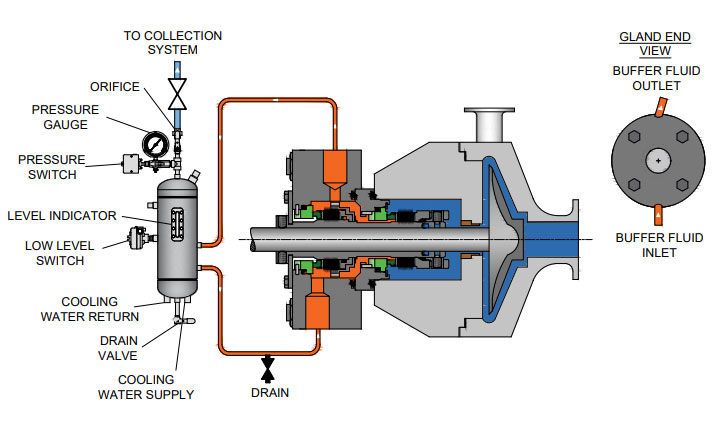
API Plan 52 takes buffer (unpressurized) fluid from a reservoir (seal pot), delivers it to the seal chamber, circulates it between the inboard and outboard seals using a pumping ring located driven by shaft rotation, then returns the fluid to the reservoir. In the event of an inboard seal failure, process fluid leaks into the seal chamber. When that occurs an increase in buffer fluid pressure and/or level alerts operators to the problem. The outboard seal, however, contains leakage until maintenance can replace the damaged seal.
This plan can include cooling coils in the reservoir to maintain the required buffer fluid temperature, visual or mechanical fluid level indicators, pressure and level transmitters, and connection to a collection system and buffer fluid replenishment source.
The overall design of this API plan for a double mechanical seal is relatively simple in comparison to other plans. Design decisions involving tubing size, length, geometry, type (carbon vs stainless steel), buffer fluid type, and volume of the buffer fluid reservoir are critical in maintaining the proper operating environment for the double seal. If you don’t have this expertise in-house, work with an experienced, local seal support system vendor to ensure the API Plan 52 is designed to meet your specific pumping requirements.
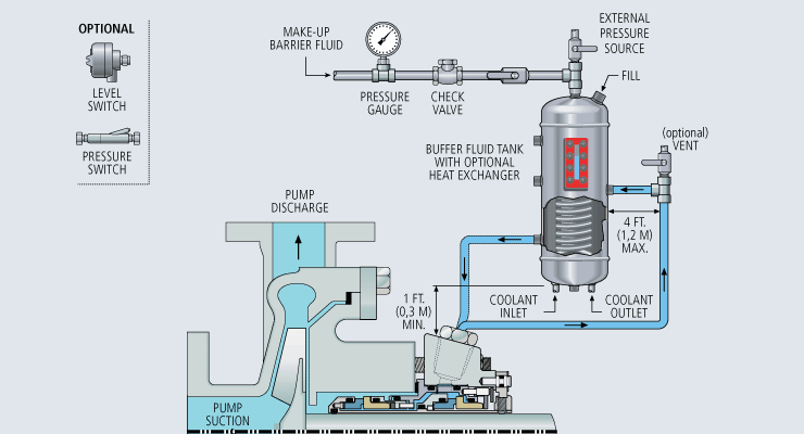
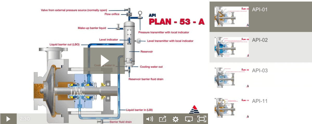
API Plan 53A is conceptually similar to API Plan 52 with the difference that the fluid being circulated between the double mechanical seals is under pressure. A pumping ring is used to circulate the fluid. The reservoir that contains the barrier fluid is pressurized by plant nitrogen. Reservoir pressure should be set a minimum of 20 to 25 psi (1.4 to 1.73 bar) above the maximum seal chamber pressure, allowing the barrier fluid to leak (and lubricate) across the inboard seal faces into the process fluid. For this reason, the barrier fluid must be chemically compatible with the process fluid.
Because barrier fluid is depleted as it moves across the inboard seal faces, it needs to be replenished. This can be done manually or automatically by way of a system that serves multiple pumps. API Plan 53A design options include reservoir type and volume, cooling coils, fluid level and pressure indicators, and transmitters to alert to level or pressure changes that indicate seal failure.
When you choose an API plan for a double mechanical seal, your primary decision is between a buffer or barrier plan. I’ve highlighted two of the API plans for double mechanical seals above to show the basic differences. There are multiple API plans for double mechanical seals to choose from—pressurization from bladder or piston accumulators, plant nitrogen delivered directly to the seal chamber, and custom-engineered external systems. Your choice will be determined by the process fluid and pumping conditions and the type of double mechanical seal your vendor recommends.
With this information in hand, it’s best to work with an experienced local seal support system vendor. They’ll be able to meet with you on-site to review the specifications for the pumping process, the pump, and the double mechanical seal. They’ll evaluate your existing infrastructure and its influence on seal support system design. Based on this information, they’ll then design the seal support system to meet the specific pumping requirements.
If you work with a global vendor like Swagelok, based on the design, we can quickly assemble and thoroughly test the API plan at our local facilities prior to delivery. We’re also conveniently available for follow-up consultations, on-site, remotely, or by way of a quick phone call.
For well over 50 years, Swagelok has worked closely with Northern California process industries to confidently choose the right API plans for pumping needs. Our locally based Field Engineers and certified technicians provide field verification of your seal support requirements, designs based on best practices gained from global experience.
To find out more about howSwagelok Northern California can help you choose the right API plan for double mechanical seals, as well as process and atmospheric side seals,contact our team today by calling
Morgan holds a B.S. in Mechanical Engineering from the University of California at Santa Barbara. He is certified in Section IX, Grab Sample Panel Configuration, and Mechanical Efficiency Program Specification (API 682). He is also well-versed in B31.3 Process Piping Code. Before joining Swagelok Northern California, he was a Manufacturing Engineer at Sierra Instruments, primarily focused on capillary thermal meters for the semiconductor industry (ASML).
Mechanical seal failure due to unfavorable operating conditions is an issue in every industry. Double mechanical seals especially require proper sealing accessories to create suitable operating environments which are key to increasing MTBF. Reservoir systems are one of the most common and effective options to supply cooling fluid crucial to successful seal operation.
A double -or dual – cartridge seal is defined as an arrangement of two mechanical seals in a series. These seals may be configured in various orientations within the cartridge. The seals themselves are referred to as the “primary” (or inboard) seal and the “secondary” (or outboard) seal. A double seal arrangement is the superior option to a single cartridge when it is imperative the product being pumped does not leak into the atmosphere. The API (American Petroleum Institute) Standard 682 classifies dual seals into two configurations. These configurations also apply to ASME (American Society of Engineers) B73.1 and ASME B73.2 pump designs.
Arrangement 2 (Unpressurized) Designs: the buffer fluid is the operating environment for the secondary seal and forms a “buffer” between the process fluid and the atmosphere.
Arrangement 3 (Pressurized) Designs: the barrier fluid is the operating environment for both the inboard and outboard seal, preventing process leakage to the atmosphere.
Buffer and barrier fluids may be either liquid or gas. These fluids lubricate seal faces during operation as well as regulate operating temperatures by moving heat—both generated and absorbed—away from the faces.
Seal support systems are necessary for the smooth operation of a dual mechanical seal. Here are two of the most common piping plans for these systems.
This is an unpressurized system consisting of a reservoir, supply and return lines, and an internal circulation device within the outer seal (commonly referred to as a pumping ring). The buffer fluid circulation rate is dependent on how this circulation device functions during seal operation.
Reservoirs may be fitted with a variety of measurement devices such as a liquid level indicator and pressure gauges as well as valves and switches to aid in various operation and maintenance functions. For instance, a typical support system configuration for natural gas liquids (NGL) would issue an alarm (visual, audible, or both) when the inner seal fails. In addition, the outer seal would take over the primary seal function until maintenance is performed.
This system forces gas from an external pressurized source into the reservoir to pressurize the barrier fluid. This means the reservoir pressure will be above seal chamber pressure; a guideline is a minimum of 20 to 25 psig (1.4 to 1.73 bar) above the maximum process pressure.
The Plan 53A is also used to maintain a specific operating temperature range to ensure optimum lubrication at the seal faces. The reservoir houses a cooling coil which actively cools the barrier fluid as necessary.
As with the Plan 52, a circulation device is used to move the barrier fluid. Replenishing a Plan 53A system with fresh barrier fluid can be as simple as a using a hand pump or a more complex arrangement which satisfies multiple seals.
& 5. Fuels such as diesel or kerosene, and alcohol solutions may also we used, but it is imperative that these fuels be evaluated for safety and compatibility before put into service.
Liquid-lubricated dual mechanical seals require an external source of clean, cool lubricating fluid. The following fluid reservoir systems create this enhanced sealing environment, enabling longer operational life for dual seals.
In the oil and gas industry, reliable seal operation is critical to running efficient, safe processes. In conjunction with API 682 Piping Plans 52 and 53A, seal support systems aid in smooth seal operation.
If you require an engineered seal support system or are interested in additional options to Flexaseal’s ANSI PLUS and ANSI LITE support systems, please contact our applications engineering team.

To keep mechanical seal systems functioning as long as possible, we recommend using standardized seal piping plans. Detailed API seal piping plans ensure minimal seal face wear by maintaining the optimal seal chamber environment.
Since they were first formulated, seal piping plans have been maintained and remodeled by the American Petroleum Institute (API). Current plans are based on API 682 and are sorted numerically. In some cases, designated letters are also used to differentiate between plans.

Please contact AESSEAL Systems Division for further details. Tel: +44 (0)28 9266 9966 Email: systems@aesseal.com For more information, and a video demonstrating the piping plan in operation, select a plan below
In Part 3 of our series on Double/Dual Mechanical Seals we take a look at the best piping plans/support systems to put in place to increase seal/equipment reliability and reduce energy/water costs.
More importantly, to extend the life of a double/dual seal, you want to control the fluid film that comes into contact with the primary seal faces to establish the ideal lubrication, temperature and pressure within the seal. Across all types of mechanical seal failures, inadequate/incorrect seal support systemsare the second highest cause of seal failures (Figure 1).
Standard environmental control plans (also called piping plans) have been developed for double/dual seals and choosing the right environmental control plan is critical to your seal performance and reliability.
This plan is used when working with hazardous process fluids in which no leakage into the product can be tolerated. It provides a backup seal in case of inboard seal failure.
If an inner seal leak is not detected early enough, the higher pressure process fluid will displace the buffer fluid. This can result in the process fluid completely filling the barrier fluid chamber between the inboard and outboard primary seals. Should the outer seal leak, product will be released into the atmosphere.
This plan is used in services where no product leakage into the atmosphere can be tolerated. Plan 53’s biggest advantage over Plan 54DM, which does not use a tank, is its limited fluid volume. The amount of fluid that can enter the product system is limited to the volume of the barrier fluid tank itself (usually 2-3 gallons or 8-12 liters).
Uses a pressurized external reservoir or barrier fluid tank to provide a clean, pressurized barrier fluid to both the inboard and outboard primary seals of a pressurized double/dual seal.
Leakage of barrier fluid into the product will always occur to some extent. Normally this leakage will be small and can be monitored by the barrier tank fluid level. Therefore, the chosen barrier fluid must always be compatible with the process fluid.
The tank pressure must be maintained at the proper level. If the barrier fluid tank pressure drops, the system will begin to operate like a Plan 52, or unpressurized dual seal, which does not provide the same level of sealing integrity. Specifically, the inner seal leakage direction will be reversed and the barrier fluid will, over time, become contaminated with the process fluid.
Directs a clean compatible fluid into and out of the dual mechanical seal barrier/buffer fluid ports. The purpose of this fluid is to prevent the pumped fluid from damaging the inboard seal faces, to remove heat from the seal, and to lubricate the outboard seal faces.
Careful consideration should be given to the reliability of the barrier fluid source. When the source is interrupted or contaminated, the resulting seal failures can be very costly.
The higher the differential pressure, the more transfer/migration into the product. The control should never be used where the barrier fluid pressure is likely to fall below seal chamber pressure. If this were to happen, the failure of one inboard seal from any mechanical seal in the system could contaminate the entire barrier fluid system with product and cause additional seal failures.
Once the inboard seal wears out or fails, the amount of barrier fluid that entered the product system is virtually unlimited unless it is shut down quickly. Alerting instruments should be put in place to avoid this.
Using appropriate monitoring devices, alarms, switches, etc. will provide a means to monitor the health of your double/dual seal to identify potential issues in advance avoiding costly unplanned outages. A basic Plan 52 buffer system will have a sight glass to monitor the buffer fluid level, a pressure gauge and connections to and from the mechanical seal, as well as a vent and drain valve. Cooling coils and level switches are typically available as optional items.
A Plan 53 would have the same features as the Plan 52 with the addition of a pressure regulator, safety valve, and an optional pressure switch. These systems can be customized to meet customer specifications should they desire to have additional features incorporated into the system.
For assistance with using the best seal support system for your specific challenge, ask your local Chesterton office or contact our Ask the Expert service.
Plan 52 uses an external reservoir for providing buffer fluid for the outer seal of an unpressurised dual seal arrangement. Cooling coils in the reservoir are available for removing heat from the buffer fluid.
For Plan 53A, reservoir pressure is produced by a gas, usually nitrogen. A pumping ring maintains circulation during operation. Thermosiphon action is in effect during standstill. Reservoir size can be optimised in accordance with the flow rate. Any particles tend to settle at the bottom of the reservoir and don"t get recirculated. Similar to Plan 52, cooling coils are also used. Proper safeguards against the backflow of barrier fluid into the external supply of nitrogen also need to be considered.
Plan 53B makes use of an accumulator for isolating the pressurizing gas from the buffer fluid. A heat exchanger is also included in the loop in order to cool the fluid. It can either be water cooled, finned tubed, or air-cooled, depending on the system heat load.
Plan 54 employs an external source for providing a clean pressurised fluid. Plan 54 systems can be custom-made so as suit various application requirements and provide pressurised flow to various seal installations, thus keeping costs down.

The mechanical seal is the most likely part of the pump to fail. Approximately 70% of the pumps removed from service for maintenance are victims of mechanical seal failure. Mechanical seal parts are highly engineered with very close tolerances and any upset in the pump or associated system can cause seal failure, including:
Mechanical seals are based on positioning two very flat and smooth discs called seal faces, one rotating on the shaft and one stationary in the pump, against each other. The discs are flat and smooth enough to ALMOST prevent the pumped fluid from leaking out between them. However, the faces do rely on a very thin film of fluid between the faces to lubricate that rubbing fit. Without this film of fluid, the seals will overheat and fail. Lack of lubrication is the PRIMARY cause of seal failure. If the fluid is very hot, it can flash to a vapor as the fluid moves across the faces, again resulting in lack of lubrication. Note that gas seals use a gas film between the faces to minimize face contact and heat buildup.
Seal flush plans are intended to keep the area around the seal in the most seal friendly environment practical, usually meaning clean and cool. Dual seal plans also provide backup and leak detection for safety.
Note that seal flush plans use pressure differences at the pump to drive the flush fluids. The pump suction is low pressure, the seal chamber is a medium pressure, and the pump discharge is at high pressure.
As the seal faces faces rub together (with their thin film of lubricating fluid), they generate heat. The heat can build up in the seal chamber and push the fluid towards its boiling point, resulting in premature flashing, lack of lubrication, and failure. This first set of seal plans is intended to create circulation through the seal chamber to dissipate the heat out of the seal chamber and back into the pumped fluid.
Flush fluid flows from high pressure at pump discharge to the medium pressure seal chamber and back into the main flow to remove heat from seal chamber
Can be used to increase seal chamber pressure. Increased chamber pressure may be required to keep chamber fluid from flashing to vapor or to provide enough pressure to push the fluid between the faces for lubrication. (Seal chamber must be 5 psi minimum above external atmospheric pressure).
These seal plans are intended to provide the seal with the friendliest environment possible by cooling and/or cleaning the fluid in the seal chamber. The throat that separates the seal chamber from the main pumped fluid can be further restricted by adding a close clearance bushing in the bottom of the seal chamber, better isolating the cool, clean seal chamber fluid from the hot, abrasive fluid in the pump.
Rather than a Plan 21 single pass system, a Plan 23 is a multi-pass system. Fluid comes FROM THE SEAL CHAMBER instead of the pump discharge, is cooled, and directed back to the seal chamber.
Fluid is driven out of the chamber and through the cooler by “pumping ring” or other “pumping feature” built into the seal. These features provide very little differential pressure. Connecting tubing must have long, sweeping bends, well vented high points, and low point blowouts to ensure fluid flows.
Quench piping does NOT change conditions inside the seal chamber, at the wet side of the seal faces. Rather, it affects or monitors the environment on the ATMOSHPERIC side of the seal faces.
Pumps that leak when they are filled, even before they are started, often have a flush line intended for a Plan 11 or 13 connected to the QUENCH port, leading to the atmospheric side of the seal. There should be a “Q” or the work “QUENCH” stamped in the gland at this port.
For flush plans Plan 65A, 65B, 66A, and 66B, facility owners may want to know if their seals are leaking excessively without going to the expense of dual seals. These seal plans direct excessive leakage on the outside of the seal to an alarm instrument. Remember that seals leak a little bit. They need to in order to lubricate the faces and function correctly. The plans below handle the nuisance leakage in different ways.
Used in salting services like sodium hydroxide. The leakage across the seal faces will turn to salt when it reaches atmosphere. The salt crystals can wear the faces or build up in the seal, preventing the movement necessary to keep the seal faces in contact. The salt on the outboard of the seal can be washed away with a water quench through the quench and drain ports. Usually a close clearance bushing is installed at the extreme outboard end to the seal assembly to help keep the quench fluid moving from the quench to the drain port (or vice versa) and not just run out along the shaft. Also used for slurry services.
Grease can be introduced into the quench port. This external grease can provide temporary lubrication to the seal in case the pump sees large air or vapor pockets which would normally rob the seal faces of the required lubricating fluid film.
Quench can also be gas. In hot hydrocarbon services, the fluid will turn to solid coke when it reaches the atmospheric side of the seal. The fluid would remain a liquid if the area outside the seal faces is robbed of oxygen with a flood of nitrogen or steam.
An alarm does NOT necessarily mean a failed seal. The collection vessel might be full from years of nuisance leakage. Try emptying the vessel and observing how fast the vessel fills.
Two throttle bushings are used to ensure that the vapor (or fluid) leakage is limited along the shaft and out of the drain. A pressure switch picks up a rise on pressure above nuisance levels on the outboard side of the seal.
Dual seals provide a backup seal in case the primary seal fails. They prevent hazardous fluids from leaking to the surrounding area, desirable for both environmental protection and the safety of nearby personnel. Dual seals also capture and control any leakage of pumpage across the primary seal. The backup seal is kept lubricated by introducing a buffer/barrier fluid (often a mineral or synthetic oil, a water/glycol mix, or diesel) into the space between the primary (inboard) and secondary (outboard or backup) seals. The buffer/barrier fluid is contained in a tank (5 gallons is most common) adjacent to the pump. Instrumentation on the tank indicates what is happening with the seals.
Remember that a lubricating fluid film will flow from high pressure to low pressure. If the pump seal chamber pressure is higher than the pressure on the other side of the seal, the pumpage will be the lubricating film. If the pump’s seal chamber pressure is lower than the external pressure, the external atmosphere will migrate into the pump. Pumps under vacuum cannot use an ordinary single seal, since air from the atmosphere would be drawn between the faces, causing them to run dry and fail. Using a dual seal allows a fluid to be present at the outside of the seal. In a pump under vacuum, the buffer fluid would be pulled into the pump between the seal faces, keeping the inboard seal well lubricated.
If the pump seal chamber pressure is higher than the BUFFER fluid between the primary and backup seal faces, then the pumped fluid will flow from the high seal chamber pressure into the low pressure buffer fluid. This is called a DUAL UNPRESSURIZEDseal (formerly called a tandem seal), and the fluid is called a BUFFER fluid.
If the pump seal chamber pressure is lower than the BARRIER fluid between the primary and backup seal faces, then the barrier fluid will flow across the primary seal from the space between the primary and backup seals into the pump. This is called a DUAL PRESSURIZEDseal (formerly called a double seal), and the fluid is called a BARRIER fluid.
Buffer fluid circulates from the buffer fluid reservoir, through the space between the primary and backup seal, and back to the reservoir. Fluid is circulated by a weak pumping action built into the seal.
It the fluid flashes to vapor at low pressure, the vapor is piped to a flare or vapor recovery system, through an orifice at the top of the tank. If the primary seal is allowing too much leakage, the vapor will build pressure in the reservoir against the orifice and a pressure instrument can alert the operator.
If the fluid remains as a liquid under low pressure, any leakage will cause the fluid level in the buffer tank to rise, where a high level alarm can be tripped. Just because the high level alarm is tripped does not mean that the primary seal is failing; it is the rate of leakage filling the tank which matters. The high level may have been reached after collecting years of nuisance leakage. Often, an oil change to the original level is all that is required. Be sure the fluid is disposed of properly.
Seal face friction or hot pumpage can add heat to the buffer fluid. A cooling water coil is often installed in the reservoir to cool the buffer fluid.
Dual pressurized system (seal barrier fluid is at a higher pressure than the pump seal chamber). Pressurized systems are used to ensure that very dangerous fluids remain in the pump. The difference between 53A, 53B, and 53C is the method of pressurizing the barrier fluid. Pressure in the barrier fluid should be at least 10 psi over the pressure in the pump seal chamber.
Barrier fluid circulates from the barrier fluid reservoir, through the space between the primary and backup seal, and back to the reservoir. Fluid is circulated by a weak pumping action built into the seal.
A low level alarm in the reservoir alerts the operator that a seal may be failing, allowing the barrier fluid to enter the pump through the primary seal or the atmosphere through the backup seal.
Seal faces can be designed to maintain a gas film between them rather than a fluid film. These piping plans are intended to work with theses gas film (dry running) seals. Plan 72 and 74 bring the buffer or barrier gas into the seal; plans 75 and 76 are for the gas exiting the seal.
Secondary seal is ordinarily running with a gas film between the faces. When the primary seal fails, the pumped fluid will fill the space between the primary and backup seal. The backup seal is now working as a liquid seal rather than a gas seal and is designed to run for about 8 hours, allowing the operators time for an orderly pump shutdown.
Plan 72 buffer gas flow keeps the gas in the seal from becoming concentrated from nuisance leakage over time so that any leakage from the gas backup seal is mostly inert flush gas and not toxic pump vapors.
In LIDERING we have an extensive range of mechanical seals for all types of pumps: from seals for domestic pumps to seals for process pumps, specific in complex applications in the chemical and petrochemical industry. In addition, we offer a wide range of spare parts compatible with the originals of the main manufacturers of pumps (RMS). Our catalog also includes cartridge seals for more demanding industrial processes, and our extensive range of products is ever-growing in order to adapt to the requirements of our customers.

Mechanical seals are used in millions of process pumps; the many available seal configurations are described in the standards of the American Petroleum Institute (API-682). These standards also describe the many flush plans (piping plans) used by modern industry. Except for automotive, home appliance and similar applications where the pumpage fully envelops the sealing components, a flush liquid stream and associated piping plans are used to remove heat from the seal faces.
There are many manufacturers of mechanical seals and their overall strategies appear similar: each desires to deliver safe products at reasonable cost. However, the business objectives of the very best mechanical seal manufacturers go beyond the obvious. Their objectives are expressed in marketing approaches which consistently represent value.
Superior service and high customer satisfaction are among the discernibly beneficial aspects of good marketing. Additional benefits accrue if the seal’s service and asset provider conveys educational or training updates to the ultimate seal user.
Such opportunities exist based on new flush plans found in the 4th edition of API-682; they are Plans 03, 55, 65A and B, also Plans 66 and 99. Although these five flush plans and their derivatives are little known, they can be of great advantage in certain services.
The new API Plan 03 (Figure 1) is a great addition; it relates to a taper-bore seal chamber for an API pump. For decades API pumps have been using closed (cylindrical) seal chambers and have relied on piping plans to maintain a chosen seal environment. However, because taper-bore stuffing boxes are now very well proven in American National Standards Institute (ANSI) pumps in contaminated services, we also now can specify tapered bores for API-compliant pumps.
In Plan 03 the flush fluid flows into the pumpage. Circulation between the seal chamber and the pump is facilitated by the tapered geometry. Solids accumulation risk is greatly reduced by the tapering and the former stuffing box is now part of the back pull-out cover of this pump. New pumps can accommodate the tapered design, as will pre-existing pumps through a modification or upgrading process. It should be noted that the taper should be relatively steep; 30 to 45 degree inclination has worked well. Very shallow taper angles should be avoided.
This seal chamber geometry promotes circulation which, in turn, provides cooling for the seal and vents air or vapors from the seal chamber. Flush Plan 03 is most often used in applications where the seal faces generate relatively small amounts of heat. Plan 03 is also used in applications where the old-style cylindrical chamber would have allowed solids to collect. Occasionally, the tapered bore is fitted with anti-swirl vanes (sometimes called “swirl interrupting ribs”) for even greater assurance against solids accumulation.
In Plan 55 (Figure 2), there is an unpressurized external buffer fluid system supplying clean liquid to the buffer fluid seal chamber. Plan 55 is used with dual (double, tandem) liquid seal arrangements. The buffer liquid is typically maintained at a pressure less than seal chamber pressure and less than 0.28 MPa (2.8 bar or 40 psi).
Plan 55 is similar to Plan 54 except the buffer liquid is unpressurized. The Plan 55 representation in Figure 2 shows an efficient bi-directional tapered pumping ring. This particular ring greatly assists in moving the buffer fluid to and from an external reservoir and/or through an external heat exchanger (cooler). Also, the potential advantages of using a tapered pumping ring can be significant. One such model, as seen in Figure 2, is offered with bi-directional functionality and a wide clearance between its vane tips and the opposing stationary parts. In the event of pump bearing distress, this wide clearance gap protects against scraping and extreme heat generation.
The outboard seal in Figure 2 is a wet containment seal (API calls it configuration 2CW-CW—dual contact wet seal) and is normally used in services where process fluid leakage to atmosphere must be avoided, which is to say minimized and contained. Many users found Plan 55 advantageous in applications where the process was prone to solidify in contact with atmosphere or in applications where additional heat removal from the inner seal was required.
Examining major seal manufacturer Websites allows users to see how Plan 55 differs from Plan 52. In Plan 52 the buffer liquid is not necessarily self-contained; with Plan 52 buffer liquid circulation is created by an external pump or pressure system. If Plan 55 is
In Plan 65A/B there is an atmospheric leakage collection and detection system for condensing leakage. Failure of the seal will be detected by an excessive rate of flow into the leakage collection system. Figure 3A and Figure 3B is intended to convey that many different seal configurations are allowed; the emphasis is largely on leakage monitoring. The central port is equipped with one of many feasible instruments. In any event, Figure 3 depicts a standard setup when pumped fluid condenses at ambient temperatures.
Plan 65A/B is normally used with single seals in services where the anticipated seal leakage is mostly liquid, not gas. Piping is connected to the drain connection in the gland plate and directs any primary seal leakage to an exterior collecting volume or system.
The exterior collecting reservoir (the “volume”) is not usually provided by the seal manufacturer; the “volume” could be an oily water sewer or some other environmentally acceptable liquid collection system in the plant. Within the seal, excessive flowrates would be restricted by the orifice located downstream of the reservoir and are redirected to it, causing the level transmitter to activate an alarm.
The orifice shown with Plan 65A (Figure 4) is typically 5 mm (about 0.25 inch); it should be located in a vertical piping leg to avoid accumulation of fluid in the drain piping. The piping allows bypassing the orifice so as to effectively self-drain excessive leakage amounts. A pressure transmitter can be provided as a monitoring alternative to the level indicator-transmitter (LIT) as shown.
Plan 65B is very similar, as seen in Figure 5. A needle valve can be trimmed to suit the user’s needs. Major leakage bypasses this valve and flows away. The rate of leakage can be safely tracked by the LIT. The leakage collecting reservoir again has to be mounted below the seal gland to allow gravity flow from seal to reservoir. A valve is usually located between seal and reservoir; it has to remain open during operation and should be closed during controlled maintenance events only.
Plan 66 (Figure 6) is a leakage detection plan often used by the pipeline industry sector for duty in remote applications. Here, high leakage flow is of prime interest. Note how a suitably orificed (or valve-equipped) pressure transmitter would be connected to the central port of this cartridge seal. Under conditions of high leakage flow, the resulting pressure rise would trigger an alarm.
This approach will probably be similarly effective with more viscous fluids. Indeed, alternative versions have appeared in production areas with a closed valve on the outlet rather than the orifice. The valve will require periodic opening to drain off the “normal” or reasonably expected seal leakage. By trending the time interval between drain-downs users obtain accurate data on the condition (or even failure trend) of a single seal.
Bearing protection takes on a special significance in remote pipeline pumping. Figure 6 prompts the author to bring this to the reader’s attention. An advanced bearing housing protector seal is illustrated, as in several of the preceding figures.
There could also be an engineered piping plan not covered by present API standards—a plan executed to the customer’s orders. A knowledgeable customer still wants to listen to manufacturer’s advice and experience.
To recap and summarize our opening paragraphs: There are many manufacturers of mechanical seals and their overall strategies seem similar. Special seals and special applications are of interest to reliability-focused users. Such users often seek out seal manufacturers whose overarching desire it is to go beyond delivering safe products at reasonable cost.
These may be companies other than your traditional alliance partners; they will, by definition, be manufacturers whose marketing approaches consistently represent value. They must be able to point to superior service and high customer satisfaction. And they must have the desire to teach. We consider them seal service and asset providers who willingly convey educational and training updates to the ultimate seal user.
Heinz P. Bloch resides in Westminster, Colorado. His professional career commenced in 1962 and included long-term assignments as Exxon Chemical’s regional machinery specialist for the US. He has authored over 600 publications, among them 19 comprehensive books on practical machinery management, failure analysis, failure avoidance, compressors, steam turbines, pumps, oil-mist lubrication and practical lubrication for industry.

Seal Support Systems operate to control the fluid in between and around the seal faces whether cleaning, cooling or heating the seal media or providing a separate fluid to the mechanical seal.
Some applications are simply not suitable for mechanical seals e. g applications which are corrosive, abrasive, crystallizing or precipitative. In order for a mechanical seal to operate under these applications with reasonable mean time between failure (MTBF), either the seal fluid requires treatment before coming into contact with the seal faces or an external fluid is required which is compatible with the process. Also double mechanical seals will require some sort of fluid to act as a buffer or barrier fluid andthe system which provides this buffer or barrier fluid are Seal Support Systems.
A seal plan is used in conjunction with the API 682 Standard and it is a way to formalise the different seal support systems into a standard. It consists of seal flush plans, buffer & barrier fluid plans, quench plans and gas supply plans.
The API Plan 53A is a dual seal plan where a barrier fluid is supplied to a double mechanical seal between the 2 sets of faces of the mechanical seal.
Plan 62 is a quench seal plan where a fluid is supplied to the space between the atmospheric side of the mechanical seal and the throttle bushing on the shaft.
Flowserve provides Seal Support Systems for in accordance with API 682 but can also provide systems outside of this standard, if the application dictates.
Our Mechanical Seal specialists can advise you on the appropriate selection of a seal support system which will deliver years of reliable service and operating cost savings in the longer term.

I am sorry. I can"t answer your question. You should contact a mechanical seal manufacturer and give them some "average" conditions such as seal size, service, metalurgy, etc. As I intended to say above, there are far too many variable to give a reasonable answer.


 8613371530291