
balanced mechanical seal quotation

Optimal performance is attained by selecting from three standard seal face balances; the BXQ seal is high balanced for flashing hydrocarbon applications
• Drive mechanisms external to the product;• Seal faces positioned for maximum protection;• A dynamic elastomer moves on a non-metallic surface, eliminating fretting defects;• Hydraulically balanced;• ...
Cartridge seals for critical, toxic and emission control applications, where single seals are notaccepted;• Built-in pumping device improves barrier fl uid cooling;• Springs locations prevents contact ...
... corrosion;• Monolithic rotating unit virtually eliminates clogging in the seal area;• A dynamic elastomer moves on a non-metallic surface, eliminating fretting defects;• Hydraulically balanced;• Cartridge ...
Single mechanical seal, balanced, independent of the direction of rotation with multi-spring configuration. The MTM180 Series represents the mechanical seal ...
Single mechanical seal, balanced, external, independent of the direction of rotation with multi-spring configuration. The MTM190 Series represents the mechanical seal ...
Single echanical seal, balanced, independent of the direction of rotation with multi-spring configuration. The springs are never in contact with the fluid. The MTM190 Series represents the mechanical ...
... dual unpressurized arrangement, without outboard seals also incorporating the same non-pusher technology, the seal can be configured to suit both the operator and pipeline needs.
Flexible seal, suitable for the narrower seal housing and suitingcommon European seal housing standards. STK A1 has a longworking length and is fitted with a seal head ...
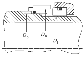
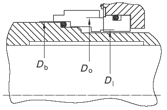
As a means of quantifying the amount, or percent, of balance for a mechanical seal, a ratio can be made between the seal face area above the balance diameter versus the total seal face area. This ratio can also be expressed as the area of the seal face exposed to hydraulic closing force versus the total seal face area.
As a general rule of thumb, balanced seal designs use a balance ratio of 0.75 for water and non flashing hydrocarbons. For flashing hydrocarbons, which are fluids with a vapor pressure greater than atmospheric pressure at the service temperature, the balance ratio is typically 0.80 to 0.85. Unbalanced seal designs typically have a ratio of 1.25 to 1.35.
Balance diameter varies with seal design, but for spring pusher seals under outer-diameter pressure, it is normally the diameter of the sliding contact surface of the inner diameter of the dynamic O-ring; for spring pusher seals under inner-diameter pressure, it is normally the diameter of the sliding contact surface of the outer diameter of the dynamic O-ring; for welded metal bellows-type seals, the balance diameter is normally the mean diameter of the bellows, but this can vary with pressure.
Temperature control plays an important role in the success of a mechanical seal. Every seal generates heat at the seal faces. In some cases, heat soak from the fluid pumped should also be controlled. Heat soak is the heat transferred from the pump and pumped fluid to fluid in the seal chamber. For example, if a particular fluid must be maintained at 60 °C (140 °F) to maintain a satisfactory vapour pressure margin and the pump operating temperature is 146 °C (295 °F), heat would be transferred through the pump case into the seal chamber.
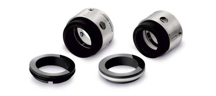
Ashish Seals is one the of the major Reverse Balanced Mechanical Seal manufacturers, suppliers and exporters in Mumbai India. We are ISO 9001-2015 certified reliable manufacturer of Reverse Balanced Mechanical Seals that is designed to handle abrasive or corrosive media. As the metal components of this kind of seal do not come in contact with the media to be sealed, it is widely in demand. The offered mechanical seal is compact in design; hence neither axial nor radial extra space is essential for its installation. Such seals are used to handle hydrocarbons, corrosive chemicals, general & light chemicals.
Reverse Balanced Mechanical Seal is externally mounted and are multi coil spring seals. Liquid pressure is used for closing the seal faces. Thus, it is very useful in vacuum and high pressure applications. As it eliminates the shaft step or sleeves for balancing, this makes it a unique seal. It can be exceptionally useful light corrosive and contaminated liquid. The metal does not come in contact with the media. Such seals eliminate the elastomer’s movement. Hence it reduces fretting effect on shaft efficiency.
we are engaged in offering an assortment of Multi Spring Reverse Balanced Mechanical Seals. The offered range find its applications in various industries such as chemical, refinery, petrochemical and pharmaceutical. These seal can be easily assemble or dismantled through cir-clip provided and can be change to balance version.Witch can be provided with single, double or tandem arrangement with external seal support system & devices.
"Multiple spring Revesed Balance Mechanical Seals" are externally mounted internally balanced multiple spring seals. the unique feature of this type of seals is that, it eleminated the shaft step or sleeves for balancing. these seals are externally mounted and hence the metal parts including the spring do not come in contact with the surculating media and therefor can be used for corrosive or abrasive media sealing. the compact design eleminates the requirement of extra radial and axial space for its installation.

Type MI250C is a multiple spring high-performance seal specially developed for Slurry application. The springs are protected from the Media by means of dynamic ‘O’ Ring. Although being a balanced seal it doesn’t require step on Sleeve. The Sleeve of the unbalance Seal can be used for this seal series without modification. Torque transmission to the seal ring is given by strong multiple drive Pins/Lugs. This seal can be run against many different stationary seal rings for maximum flexibility in many applications. This seal has a balanced O-Ring design with anti-clog features, springs out of the fluid and dynamic O-Ring moves on a clean surface. The concept is ideal for stock realization. This seal are factory assembled and dynamically tested.
The scope of our mechanical seal product range far exceeds any other seal manufacturer. From small elastomer bellows seals used in millions of domestic water pumps to double mechanical seals that ensure maximum sealing safety and large, highly customized dry-running gas seals for mission critical high speed turbo compressors, John Crane has the right product for any application.
Our world-class rotating equipment technologies, paired with an unmatched breadth of applied engineering expertise, meet virtually all international standards including API 682 and help plants reduce maintenance costs, slash down time and improve reliability. When it comes to keeping your rotational equipment running 24/7, John Crane’s comprehensive range of mechanical seals and systems has you covered.
A range of seals for mission-critical applications, designed to solve the application-specific challenges of each industry. From API 682 compliance for the oil and gas industries, using gas seal technology on our innovative pump gas seals to eliminate fugitive emissions, dealing with slurry in the mining and minerals processing industries, to the difficulties associated with maintenance on large pumps and rotating equipment — we have a solution.
Dry-running, non-contacting gas seals have been the industry standard since the early 1980s for turbomachinery. John Crane gas seals, separation seals and support, monitoring, control and conditioning systems — the heart of any reliable sealing solution — are constantly evolving to meet the needs of customers. The product portfolio is supported by unrivaled global service capability providing repair, retrofit, gas seal storage and reliability expertise, delivering total solutions throughout the product lifecycle.
In industries like chemical, pharmaceutical, pulp and paper, and food and beverage, safeguarding and compliance with industry standards, avoiding contamination and efficiency are always top priorities. Our range of vessel and agitator seals optimize equipment performance, maintain product purity and conform to industry regulations, no matter where you are.
Our range of mechanical seals, packing and bearing isolators combines advanced, thoroughly proven technologies with extensive industry expertise to create a range of products characterized by innovative design concepts and outstanding manufacturing quality. Tried, tested and effective solutions for virtually any application that deliver robust performance, reduced installation times and lower maintenance costs.
Create the optimum operating environment that will ensure outstanding seal performance and reliability. Our comprehensive range of engineered pressure reservoirs, gas seal control panels, heat exchangers and abrasive separators can be combined to produce the perfect seal support system for any application.
Designed to overcome rigorous challenges, our comprehensive suite of seal face technologies combat limited seal face lubrication that adversely affects reliability, cost and durability. Our engineers designed these face treatments to extend rotating equipment life through advanced micro machined patterns and features improving seal face lubrication that optimizes equipment performance. We deliver the right face technology for the right application.
The Type RT-S64 is Balance Cartridge Mechanical having preassembled cartridge integral sleeve and gland plate. Balance Cartridge Mechanical seal is hydraulically balanced seal-face technology for reduced power consumption and heat generation enhancing seal life. It’s a non-contact type design where spring is prevented from clogging and corrosion. Multiple spring with rotating style and wave spring with demand by customer. Pressurized buffer fluid can be applied.
We also manufacture and supply Single Cartridge Mechanical Seals, Double Cartridge Mechanical Seals and High Pressure & Speed Balance as being top most mechanical seal manufacturers in Mumbai as well as known as one of the most precise mechanical seal manufacturing companies in India.
Centrifugal pumps are one of the most extensively used pumps in municipal and complex industrial applications. However, a proper sealing arrangement is imperative for these pumps to prevent fluid leakage and protect the pump’s inside from contaminants in the atmosphere. Mechanical seals are preferred for sealing the pump as they require less maintenance and are much more durable than packing seals.
There are a variety of options in the market when it comes to mechanical seal systems. Before illustrating the types of mechanical seals for centrifugal pumps, here are four key considerations when choosing the appropriate seal system.
Consider the type of fluid that will be pumped and how it will affect the seal system design—factors such as lubricity, volatility, corrosive properties, and cleanliness matter the most.
Make a choice depending on the pressure exerted on the seal face. For instance, unbalanced seals are suitable for low-pressure applications, while balanced seals are appropriate in high-pressure conditions.
Temperature considerations will help determine whether you need to choose a pump with heat-sensitive components. For example, balanced seals sustain high temperatures better than their unbalanced counterparts.
These types of mechanical seals are typically low in cost and used for more generalized purposes. However, installing and adjusting standard component seals is time-consuming and requires a fair amount of operational skills. In addition, as they are composed of separate dynamic and stationary components, incorrect installation remains the major cause of errors.
Cartridge type mechanical seals are easy to install and ensure high performance. They are a one-piece unit incorporating all sealing components into a single assembly. Cartridge seals provide substantial maintenance advantages compared to other seal types while reducing installation time and the risk of assembly errors.
Pusher seals rotate along the shaft or sleeve to maintain contact with the faces of the seal to reduce wearing and wobbling caused by any misalignment. They are less expensive and come in different sizes and designs. The only drawback is that the elastomer is subject to wear.Non-pusher type seals maintain contact with the faces without rotating axially. They function under low temperatures and high pressures. However, the bellows used in these seals must be replaced frequently to work in corrosive environments.
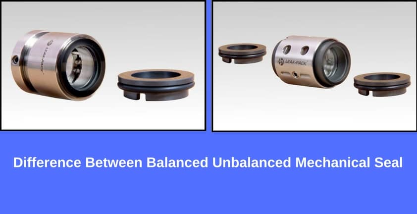
Balanced mechanical seals work at high operational pressures while generating lesser heat. They are suitable for handling low lubrication liquids and high vapor pressure. Balanced seals increase seal life by reducing the closing force.Unbalanced mechanical seals are a more economical alternative that works for low/medium pressure applications. They are highly stable and still work in conditions where there are vibrations, shaft misalignments, or fluid cavitations.

Mechanical seals form a critical part of any mechanical operation involving fluid movement through rotational shafts, such as in the case of pumps. These seals ensure that the fluid does not leak out of a closed system and contaminants do not enter the system. In pumping applications, mechanical seals are placed at the point of entry or exit of a rotating shaft, preventing the pressurized fluid from escaping the pump housing and withstanding the friction generated from the shaft rotations.
Mechanical seals are devices that accommodate a rotating shaft while containing and preventing the fluid from leaking out of the enclosed housing. While different mechanical seal designs are available for pumping applications, most have three sealing points.
These three sealing points ensure that the fluid contained within the pump housing does not leak while also preventing dust particles in the atmosphere from entering the housing.The mechanical seals are usually made up of different materials to prevent sticking. Typically, one side of the seal uses softer materials like carbon graphite, and the other is made of harder materials such as silicon carbide or ceramic alumina. However, hard materials are preferred for both surfaces if the pumping application involves abrasive fluids.
In addition to the two materials, the sealing unit also comes with O-rings to seal the stationary face on the housing side and the rotating face on the shaft side. Springs are also used to keep both faces pressed.
In most cases, the two faces of the seals are also lubricated to prevent friction and wear. Depending on the application, this fluid film can either be a separate lubricant or the process fluid itself.
Mechanical seals can be selected based on the type of pump application. Choosing the wrong seal can affect pump performance and lead to damage and costly repairs.An unbalanced mechanical seal is preferred if the pump needs to operate at a lower pressure. However, high pressure pumping applications require balanced mechanical seals. Balanced seals also perform better in high temperature operating conditions. Cartridge seals require less maintenance but are more expensive, hence used for limited applications.
At Hayes Pump, we have a fully staffed, factory-trained parts department to help you quickly with the correct mechanical seal for your pump. You canrequest a quotefor your part orcontact usto get further assistance.

Mechanical seals come in different configurations, and each variant has its advantages and disadvantages. Among the most common variants are component mechanical seals and cartridge mechanical seals.
When selecting a mechanical seal type, pump users must consider the cost of installation, long term running costs, pump characteristics, and the anticipated operational conditions (heat, vibration, and pressure). Keep your technical staff in mind as well, because having a skilled technician on-hand for regular maintenance vs. having to outsource maintenance and repairs makes a significant difference.
A cartridge mechanical seal is a completely enclosed seal system with preassembled components. Typically, this seal type is composed of a gland, sleeve, and other hardware that make pre-assembly possible.
Component mechanical seals are composed of separate dynamic and stationary parts. Unlike cartridge seals, component seals are not preassembled and require skilled technicians to install them. Incorrect installation of seal faces, O-rings, and seal axial setting on the pump shaft will result in reduced seal life or in some cases, immediate seal failure.
The major cons for non-cartridge mechanical seals are their susceptibility to damage. Other than cartridge type seals that are completely encased within secure housings, component mechanical seals usually have exposed parts that are more susceptible to damage during transportation or installation.
Further, non-cartridge type seals require precise measurements during installation to prevent seal failure. Properly installing this type of seal requires more operator time and thus a higher cost to install or re-install after a repair.

54MB? 14 CO/V/(Z //V hwy United States Patent This invention relates to a mechanical seal for sealing a shaft with respect to an enclosure from which it extends, such as the stufling box of a centrifugal pump. More particularly, this invention relates to a seal of the so-called balanced type wherein springs are utilized for creating a portion of the force urging the sealing faces together and for compressing the shaft packing and in which all springs are fully protected from contact with the fluid within the enclosure from which said shaft extends.
Mechanical shaft seals have been in wide commercial use for at least thirty years and have been constructed in a wide variety of designs. Throughout this period, one of the major problems with certain types of mechanical seals has been to protect the springs therein from corrosion by the fluid within the enclosure being sealed. This problem has been dealt with in a variety of ways but it has not previously, to my knowledge, been solved in a completely satisfactory fashion.
Referring now, for illustrative purposes, as aforesaid, to the problem of providing a seal around the shaft of a centrifugal pump, a common type of mechanical seal utilizes a stationary, annular, sealing face affixed to the pump housing and a rotating, annular, sealing face aflixed to the pump shaft. The two sealing faces are held in sealing engagement with each other and hence provide an effective seal against the passage of fluid from one side of the pump housing to the other along the shaft. Various types of resilient means, commonly metallic springs, are provided for initially urging and holding the sealing faces in sealing engagement with each other and, in many cases, for holding the shaft packing in sealing engagement with the shaft. Where the fluid either liquid or gaseous, being handled by the pump is corrosive the springs must be protected from contact with the fluid or else the seal will deteriorate rapidly. In low pressure applications, this has been accomplished by what is known in the trade as an outside seal, that is, a seal within the rotating portion thereof, including the springs, is placed outside of the housing and the mutually contacting sealing faces. This arrangement effectively protects the springs from the fluid within the pump but thus far it has been limited to relatively low pumping pressures, such as 40 or 50 p.s.i. For higher pressure applications, it has been found essential to place the rotating portion of the seal in communication with the interior of the pump housing in order to utilize the pressure of the fluid being pumped to assist in urging the sealing faces together. This is effective for sealing against high pressures, but where the fluid being pumped is of corrosive nature, this construction exposes the rotating parts of the seal, including the springs to the corrosive effect of such fluid. This can usually be handled with respect to all parts of the rotating portion of the seal except 3,l8,53. Patented Aug. 3, 1$65 the springs by selection of suitable corrosion-resistant materials. As to the springs, no materials have yet been found from which satisfactory springs can "be made and which also can resist corrosion by some of the fluids with which the sea-ls are"required to be used."
.Some attempts have been made to meet this problem by arranging flexible housings or jackets around the springs in the rotating portion of the seal but these have not been particularly satisfactory because either they have often leaked and hence failed to protect the springs anyway, of
Other attempts to meet this problem have involved the use of a so-called double seal wherein a pair of seals are arranged in a somewhat backato-back relationship with respect to each other and are located at opposite ends of a stuffing box with the space between said seal-s being filled with a pressurized sealing fluid, such as oil. This has effectively protected the springs against attack by the fluid being pumped but it is expensive, introduces substantial operating and maintenance problems, often requires more space than is conveniently"available and sometimes results in the sealing fluid leaking through the inside one of the pair of seals and contaminating the fluid being handled by the pump.
Further attempts to meet this problem have involved a type of .seal which is basically an outside seal, in that the rotating portion of the seal is outside of the housing and the sealing faces, but wherein a portion of the fluid being pumped is permitted to pass axially along the shaft to a zone within the rotating portion of the seal itself so that the fluid exerts a pressure which assists in holding the sealing faces together in a manner generally similar to that accomplished in the above-mentioned inside seals. In such a seal, often called a balanced seal, the springs by which the sealing faces are initially urged together are outside of the equipment being sealed and, hence, partake of the above-mentioned advantages of an outside seal. However, since the fluid in this case is introduced into a zone within the rotating portion of the seal, this introduces the further problem of effecting a seal between said rotating portion and the shaft. This problem is seriously complicated by the fact that the rotating sealing member is necessarily free to float slightly on the shaft, both axially and angularly, in a manner to follow slight variations from exact perpendicularity of the sealing faces with respect to the axis of the shaft. Ordinary shaft packings between the rotating sealing member and the shaft, even though of a resilient nature, have not proven satisfactory. Some attempts have been made to use spring-backed shaft packings for this purpose but all such attempts, insofar as I am aware, have resulted in these springs being exposed to the fluid being handled by the pumps and, accordingly, subject to deterioration.
("1) To provide means for mechanically sealing a rotary shaft with respect to a wall through which it extends, which seal is of the outside balanced type and has springcompressed shaft packing and wherein the springs are fully protected from contact with the fluid being handled by the equipment of which said shaft is a part.
(2) To provide a mechanical seal for equipment, as aforesaid, in which pressure fluid will be introduced into the interior of the rotating portion of the seal for pressure balancing purposes and in which the rotating sealing member will be permitted to float both axially and angularly with respect to the axis of the shaft but wherein said rotating sealing member will be effectively sealed with respect to the shaft.-
(3) To provide a mechanical seal for equipment, as aforesaid, in which shaft packing is provided between the rotating sealing member and the shaft and is backed by resilient means, said resilient means being protected from contact by the fluid being handled by said equipment.
(4) To provide a mechanical seal for equipment, as aforesaid, which will be compatible with previously known designs for such seals and hence is adapted to a variety of uses.
(6) To provide a mechanical seal, as aforesaid, in which the resilient means by which said shaft packing is compressed into position, may be readily modified or interchanged to fit a variety of different operating purposesand circumstances.
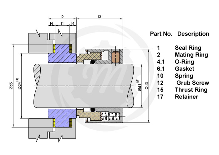
FIGURE 1 is a central longitudinal sectional view taken through a mechanical seal constructed according to the invention and shown in association with a shaft and a housing.
General description In general the invention comprises a mechanical seal of generally the outside type of construction, which seal has a zone at its radially inner side for receiving pressure fluid from within the equipment on which the seal is used. The pressure fluid supplies a balancing pressure on the axially outerside of the rotating sealing member which urges said rotating sealing member into sealing engagement with the nonrotating sealing member. Shaft packing is arranged between the rotating sealing member and the shaft on which it is mounted at a point axially outwardly. of the afore-mentioned zone. A spreader ring of suitably corrosive-resistant material is arrangedvbetween the aforementioned zone and the shaft packing. Rods are anchored in the spreader ring and extend through the shaft packing away from the zone. The rods are engaged by resilient means on the side of the shaft packing opposite the zone and suitable tension is applied thereto for pulling the spreader ring against the shaft packing and holding said shaft packing under suitable pressure so that it sealingly engages the shaft and the rotating sealing member. The resilient means, which may be coil springs surrounding the rods, are thereby protected from contact with the fluid but insure efiective operation of the shaft packing.
Referring now particularly to FIGURE 1, there is indicated a housing 1 which will be understood to refer to the housing of the pump, mixer, autoclave or other equipment with which the seal is being used. A shaft 2 extends through an opening 3 within said housing, said shaft being supported for rotation with respect to the housing All.
by an appropriate bearing means (not shown). A nonrotating seal member 4, commonly called an insert in the trade, encircles said shaft and is arranged within a suitable mounting ring 6. The ring 6 also encircles said shaft and is fastened to the housing 1 by any convenient means, such as screws,"one of which is indicated at 7. While the insert can be made of a variety of materials, as is well known to those skilled in the art, frequently it is made of a ceramic of various types and hardnesses depending on particular use requirements. The insert 4 has a planar axially outwardly facing surface 5 which functions as a stationary sealing face. The mounting ring 6 is made from a metal or allow suitable physically and chemically for the ambient conditions.
A rotating sealing member 11 encircles the shaft and has a radially extending body portion 13 whose radially inner end is spaced slightly. from said shaft to provide a passageway 12 therebetween. The sealing member 11 also has a sleeve portion 14 which extends axially away from the insert 4 and which surrounds and is spaced a substantial radial distance from the shaft 2. The member 11 also has an axially projecting annular flange 15 whose end surface 16 engages the surface 5 of the insert 4 and thus functions as the rotatable sealing face of the mechanical seal. The internal wall of the sleeve 14 defines an annular chamber 17 around the shaft 2.
A collar 18 is affixed to the shaft 2 by any convenient means, such as by set screws 19. A plurality of springs 20 are mounted in circumferentially spaced recesses 21 in the collar 18 and extend axially therefrom and engage the outer axial end of sleeve 1 The springs 20 urge the rotating sealing member 11 inwardly (rightwardly) so that surface 16 sealingly engages surface 5 to thereby prevent escape therebetween of fluid from within the housing 1.
The collar 18 has an annular boss 22 which projects a small axial distance into the chamber 17. A spreader ring 23 having, in the present case where it is used with packing of substantially V-shape in cross section, a tapered portion 24 is disposed in the chamber 17 encircling the shaft 2 and said ring is spaced axially from boss22. A plurality, here two, of substantially V-shaped, annular packing elements 26 and 26a are disposed in the chamber 17 and encircle the shaft 2 between the boss 22 and the spreader ring 23. The tapered portion 24 fits between the lips of the adjacent packing element 26aand the tapered central portion of said element 26a fits between the lips of the other element 26. Thus, when spreader ring 23 is urged toward boss 22, the lips of the packing elements 26 and 26a are spread apart into sealing engagement with the shaft 2 and the internal wall of sleeve 14.
- spring 32 encircles each rod 27 and seats at one of its ends against the head 31 and seats at its other end against the inner end wall of recess 29. The springs 32 are under compression so that the rods 27 and thereby the ring 23 are continuously urged axially outwardly with respect to the housing 1 to thereby continuously urge the lips of the packing elements 26 and 26a apart and thereby into sealing engagement with the shaft 2 and the internal wall of sleeve 14, as above described.
The space between the spreader ring 23 and the body portion 13 defines a pressure zone 36 which continuously communicates through passageway 12 with the interior of housing 1. Thus, the pressure fluid in said housing can travel to zone 36 and act therein to urge the sealing mem ber 11 inwardly to cause surface 16 to sealingly engage with surface 5. Such pressure also urges the spreader ring 23 axially outwardly to maintain the packing eleavailable to maintain such seal.
If desired, a shroud 37 may encircle the collar 13 and the sealing member ll. The shroud 37 is secured to collar ad by screws 33, said screws extending through axially elongated openings 39 (FEGURE 3) in the shroud so that the shroud 37 and the collar may move axially with respect to each other a limited distance. The shroud 37 also has openings 41 whereby the set screws 19 may be manipulated. This arrangement holds the collar 18 and sealing member 11 in association with each other so that they can be mounted on the shaft 2 as a unit. However, it permits relative axial movement of the collar 18 and the sealing member 11 as necessary to establish the proper sealing relationship between surfaces 5 and 1.6.
The remainder of the seal operates in a normal manner but same will be mentioned briefly to ensure a complete understanding of the invention. Rotation of the shaft 2 acts through the collar 18 and the drive pins 343 (or the shroud 37 if no drive pins are used) to rotate the sealing member 11. The springs 2% effect an initial engagement between the rotating sealing member 11 and the nonrotating sealing member 4 while the pressure builds up within the housing 1. When such pressure does become available, the pressure fluid enters through the passageway 12 into the pressure zone 36 and acts against the sealing member 11 to urge same in an axially inward direction and thereby hold same snugly against the nonrotating sealing member. This effect continues as the pressure builds up within the said housing and will in a well-known manner maintain the nonrotating and the rotating sealing faces snugly together in sealing relationship with each other. Pressure as high as 490 psi. have been successfully sealed by seals made according to the invention.
The sealing member 11, the ring 23 and the packing elements as and 26a, which are the only parts of the mechanical seal which contact the pressure fluid, can be made of any material desired by those skilled in the art, particularly a suitable chemically inert material so that corrosion thereof is not possible. For example, the sealing member 11 is usually made of a carbon of any desired type and hardness and the ring 23 and packing elements 26 and 26a are frequently made essentially of a tetrafluoroethylene resin.
In a mechanical seal for sealing a rotating shaft with respect to a housing through which said shaft extends, wherein a first nonmetallic sealing member is alfixed to said housing, a second nonmetallic sealing member encircles said shaft and is radially spaced therefrom, said second sealing member having a sealing surface engageable with a sealing surface on said first sealing member, said second"sealing member having a sleeve extending away from said first sealing member and surrounding said shaft to define a pressure chamber between said sleeve and said shaft for reception of a balancing pressure fluid from within said housing, and driving means aflixed to said shaft for efliecting rotation of said second sealing member with said shaft, the improvement comprising:
substantially V-shaped shaft packing means within said pressure chamber spaced axially from said wall and adapted to engage sealingly said shaft and said sleeve, said shaft packing means being of such characteristics that an axial pressure thereon will cause same to spread radially inwardly and outwardly;
a plurality of circumferentially spaced rods anchored to said compression ring and extending axially through said shaft packing means and through said passages into said recesses, said rods having enlarged heads, a coil spring disposed within each of said recesses surrounding said rod therein and bearing at one end against said rod head and bearing at the other end against the bottom of said recess for urging said compression ring against said shaft packing means and thereby urging said shaft packing means against said sleeve and said shaft whereby to seal the end of said pressure chamber remote from said wall and thereby prevent escape of pressure fluid therefrom while preventing contact of said springs by said pressure fluid.


 8613371530291