
barrier fluid in mechanical seal pricelist

This website is using a security service to protect itself from online attacks. The action you just performed triggered the security solution. There are several actions that could trigger this block including submitting a certain word or phrase, a SQL command or malformed data.
This website is using a security service to protect itself from online attacks. The action you just performed triggered the security solution. There are several actions that could trigger this block including submitting a certain word or phrase, a SQL command or malformed data.
Pumping of low-temperature and cryogenic fluids requires specific and unique engineering technologies for the shaft sealing system. When correctly applied, these technologies provide the containment and reliability to meet pumping equipment operators’ requirements.
Due to their extreme sub-zero temperatures, low-temperature hydrocarbons and liquefied atmospheric gases pose significant challenges to pumping, and particularly to the specification of their shaft sealing systems. To provide long-term reliability while ensuring that these pumped fluids are safely contained, the designs of the shaft seals used in cold-fluids pumps are often highly specialized.
For example, low temperatures have significant implications for the choice of materials used in the seal construction. Metals become increasingly brittle as the temperature is reduced; therefore, thermal constriction and expansion must be factored. The volatility and flammability of low-temperature hydrocarbons pose special challenges for the design of pump shaft seals, as well as for the release of hazardous emissions to the atmosphere. Liquefied oxygen, with temperatures much colder than these hydrocarbons, is a strong oxidizer and can cause certain materials to spontaneously combust.
Low-temperature hydrocarbons are typically pumped at sub-cryogenic temperatures, between –20°C and –140°C (–5°F to –220°F), although lower temperatures are occasionally encountered. They have high vapor pressures at ambient temperatures and are pumped at low temperatures to reduce the pumping pressures. These hydrocarbon fluids include ethylene, LNG, LPG, methane, butane and propylene.
Liquefied atmospheric gases include oxygen, nitrogen, argon and the noble gases. They are typically pumped at cryogenic temperatures ranging from –175°C to –198°C (–285°F to –325°F). Impeller inducers are often used, as they are frequently pumped with a low vapor pressure margin at the pump suction.
Low-temperature hydrocarbons are commonly pumped with API 610 (VS6) vertical multistage double-casing pumps that feature a warming chamber, known as a cofferdam (Fig. 1), which thermally isolates the shaft seal from the cold pumped fluid. Cofferdams enable a greater range of shaft sealing solutions to be used on these pumps, utilizing traditional sealing technology.
A cofferdam is a chamber between the pump discharge and the mechanical seal that is connected to the pump suction, or the vessel from which the pump is drawing suction. Ambient heat surrounding the pump, together with energy from the shaft and bearings, causes the liquid in this chamber to vaporize into a gas, which forms an insulating barrier between the seal and the process fluid. Cofferdams can be incorporated only into vertical pump designs.
Although vertical arrangements are common, various horizontal pumps can also be used. In these types of pumps, the shaft seal is in direct contact with the cold-pumped fluid; therefore, selection of the seal materials for low-temperature operation becomes more critical.
Similar to pumping equipment for low-temperature hydrocarbons, pumps used for liquefied atmospheric gases have a combination of vertical multistage pumps, together with horizontal single-stage pumps. These systems generally do not follow API pump design standards.
However, as the temperatures of liquefied atmospheric gases are much colder than those at which hydrocarbons are pumped, cofferdams cannot be used on these pumps. Although a mixture of vertical and horizontal pumps is commonly used at air liquefaction plants, mobile trailer truck unloading pumps are almost exclusively overhung single-stage pumps, either with direct-drive or speed-increasing gearboxes.
For pump designs where the mechanical seal is immersed in the pumped fluid, the vapor pressure margin in the seal chamber becomes critical. Where the vapor pressure margin is low, the heat energy from the mechanical seal faces can vaporize the fluid around the seal and in the seal interface, resulting in dry running of the seal. In this situation, a dual-pressurized seal is required. A dual-pressurized seal provides a stable barrier fluid to lubricate the seal faces, thereby negating the effect of vaporization of the pumped liquid at the seal faces.
API Plan 53B and 53C barrier systems are commonly selected for dual-pressurized seals to provide a source of warm, clean and stable barrier fluid to the mechanical seal. When an API Plan 53C system is selected, extra care should be taken to ensure that the pressure-amplifying piston and rod seals are insulated from exposure to cold temperatures.
The availability of suitable barrier fluids becomes limited at low temperatures, as the viscosity of many fluids becomes too high at the seal chamber operating temperatures. Mono- and di-ethylene glycol mixtures with water can be used down to temperatures of –29°C (–20°F). Alcohols, such as propanol (propyl alcohol), are suitable for even colder temperatures reaching –70°C (–95°F). Synthetic oils can also be used; however, careful consideration to their pour point is required, and a heating system may be needed to warm the barrier fluid to maintain a suitable viscosity.
When sufficient vapor pressure margin exists within the seal chamber, a dual-unpressurized seal can be selected. Typically, these designs feature a dry-sliding containment seal fitted with API Plan 76, or a combination Plan 72 and 76. These seal arrangements have the advantage of removing the low-temperature limitation of barrier fluid selection.
Pump designs utilizing a cofferdam require a dual-pressurized mechanical seal, as the seal chamber contains no liquid to lubricate the mechanical seal faces.
Icing, due to condensation of atmospheric humidity, can create a problem for sealing systems handling cold hydrocarbons. Since condensing water expands as it freezes, it can interfere with the operation of the mechanical seal if it reaches the seal’s operating mechanism. Extra protection should be applied to equipment exposed to atmospheric elements, such as rain. An API Plan 62 using a dry nitrogen quench can displace atmospheric humidity, thereby protecting the mechanical seal from these effects.
In applications handling liquefied atmospheric gases, pump seal reliability takes precedence when selecting a shaft sealing system. Unlike hydrocarbons, emissions of gases to the environment by liquefied atmospheric gases pose relatively minor hazards and, therefore, are not as critical a factor as seal reliability.
Two commonly employed shaft sealing technologies are used in pumps handling liquefied atmospheric gases: single mechanical seals and segmented bushings.
Single mechanical seals.The most common solution for pumps used in air liquefaction plants and mobile-transportation unloading pumps is the single mechanical seal. The major difference between the two is that the mobile unloading pumps tend to be smaller and often use non-cartridge seals. Cartridge seals are commonly found in larger machinery at air liquefaction plants. Single mechanical seals fall into two sub-categories: contacting wet seals and vaporizing liquid gas seals.
Contacting wet seals utilize a metal bellows to provide elastomer free-axial flexibility. Seal face materials typically include filled tetrafluoroethylene running against a tungsten carbide or hard-coated, stainless steel mating ring.
Vaporizing liquid gas seals (Fig. 2 and Fig. 3), similar in construction to contacting wet seals, feature engineered seal-face topography that allows the controlled vaporization of the pumped atmospheric gas to produce a highly reliable seal that exhibits controlled, low-level leakage rates.
Segmented bushings.A segmented bushings sealing configuration is often found in vertical multi-stage pumps at air liquefaction plants. The design provides a controlled leakage by breaking down the sealed pressure over a series of tightly controlled bushing clearances. Leakage rates are higher than those of mechanical seals; however, these leakage rates are often considered acceptable by this industry.
As mentioned, low temperatures have significant implications for the choice of materials used in the seal construction. This is especially true for elastomers applied in seals for pumps handling low-temperature hydrocarbons. Depending on the material grade used, elastomers have a variety of minimum temperature limits, but none can survive dynamic operation at true cryogenic temperatures.
Engineered polymer seals are an option at temperatures below the limits of elastomers; however, many of these designs will not function with pressure reversals applied to the sealing ring, which may be required in the mechanical seal design when support system failures occur.
Elastomers can survive at significantly lower temperatures below their operational limits when the seals are not in operation (i.e., static); however, they must be warmed up prior to operation. Commissioning of shaft seals containing elastomers must be completed carefully to ensure that equipment is at the correct temperatures before startup. Blowdown—the rapid depressurization of a vessel/pipeline—is one situation that can create excessively low temperatures for mechanical seal elastomers.
Thermal expansion and contraction are also considerations. The cavities in which elastomers or engineered polymer seals are installed will change with decreasing temperatures, as well as the dimensions of sealing elements installed in these cavities. Additionally, clearances between dissimilar materials, such as bushings, will require review. Mechanical seal manufacturers take these factors into consideration during the design of the mechanical seal for these cold services.
Since metals become increasingly brittle as the temperature is reduced, as a general rule of thumb, martensitic and ferritic stainless steels should be avoided in preference to austenitic stainless steels.
Since pumping equipment is often used interchangeably between different atmospheric gases, sealing of liquefied atmospheric gases presents some unique challenges to the selection of materials.
Liquefied oxygen is a strong oxidizer and can cause certain materials to spontaneously combust. Additionally, any organic contaminates on the seal can lead to spontaneous combustion, including metal cutting fluids, fibers from cleaning rags, and even oils from human fingerprints. To meet oxygen service requirements on seals, stringent cleaning specifications must be employed to ensure that the seal is free of any contaminates that may create a fire hazard while in service. Additionally, the materials of construction must include materials that are compatible for use in oxygen service.
Aluminum alloys should be avoided, as they can become hazardous when their protective oxide film is stripped from the material, such as when abrasion occurs. Lubricants used in the assembly and operation of the mechanical seal must be free of hydrocarbons and compatible for use in oxygen service. Packaging of the seal should also be suitable to preserve the cleanliness of the seal prior to installation into the pumping equipment, which must be performed in a suitably clean environment.
Of the many pump mechanical seal applications in use throughout various industries, those that deal with low-temperature and cryogenic processes rank among the more challenging.
It is critical to keep these seals, which handle low-temperature hydrocarbons and liquefied atmospheric gases, in optimal operating condition to ensure that the pumped fluids are safely contained, while providing long-term reliability. HP
Mark Savage is a Product Group Manager at John Crane, responsible for the application, design and development of metal bellows seals for pumps, compressors and rotating machinery. He has worked in the sealing industry for 25 yr and has been involved with the development of best practices for shaft seals and their support systems. Mr. Savage holds a BE degree in mechanical engineering from the University of Sydney, Australia. He is a member of the Fluid Sealing Association and Vice Chair of the Association’s Mechanical Seal Division, Chair of the Mechanical Seal Technical Committee and Vice Chair of the Government Relations Committee. He is also a member of NACE International and the Society of Tribologists and Lubrication Engineers (STLE). Mr. Savage has authored several publications on mechanical seals and support systems and their application to minimize environmental impact.
Multiple mechanical seal failures in a crude distillation unit (CDU) resulted in total losses of $3 MM in a refinery since its startup in January 2015. The maximum seal life achieved did not exceed 6 mos, which was much shorter than the American Petroleum Institute (API) 682 “Advancements in Mechanical Sealing” goal of 3 yr of seal life.
Multiple mechanical seal failures in a crude distillation unit (CDU) resulted in total losses of $3 MM in a refinery since its startup in January 2015. The maximum seal life achieved did not exceed 6 mos, which was much shorter than the American Petroleum Institute (API) 682 “Advancements in Mechanical Sealing” goal of 3 yr of seal life.
The root causes of failure for the mechanical seals for 16 hot hydrocarbon service pumps (with operating temperatures in excess of 250°C) are discussed here, and solutions are demonstrated to eliminate failures and improve plant reliability.
CDU hot pumps are equipped with API seal flushing Plan 32 (injection to seal chamber from an external source) and API seal flushing Plan 54 (pressurized external barrier fluid). API Plan 32 utilizes heavy vacuum gasoil (HVGO) that is supplied at 1.7 barg above the seal chamber pressure at 110°C. API Plan 54 utilizes light vacuum gasoil (LVGO) that is supplied at 1.7 barg greater than that of Plan 32 pressure at 110°C. For example, if the seal chamber pressure is 5 barg, Plan 32 should be supplied at 6.7 barg (5 + 1.7), and Plan 54 should be at 8.4 barg (6.7 + 1.7).
The flowrate for each API plan varies, depending on the pump service. The HVGO utilized for Plan 32 is produced from the CDU and supplied to the CDU hot pumps by a common system, as shown in FIG. 1. The LVGO utilized for Plan 54 is produced from the CDU and supplied to the CDU hot pumps by a common closed system (FIG. 2).
Mechanical seal failure data was collected from a computerized maintenance management system (CMSS), and selection criteria were set to concentrate the focus on the “bad actor” pumps. Selection criteria included an operating temperature that exceeded 250°C. The seal failure history is indicated in TABLE 1, which shows a total of 41 seal failures that occurred in 2015 vs. 25 failures in 2016. The large discrepancy in failures between 2015 and 2016 was due to a startup and commissioning period in early 2015, during which time the refinery was suffering from system dirt, operational upsets and various commissioning problems. While seal failures were reduced in 2016, equipment mean time between failure (MTBF) and seal life were unsatisfactory for refinery maintenance key performance indicators (KPIs) and targets.
A root cause analysis (RCA) was conducted in April 2016 to identify the root cause of failure for CDU bad actor pumps to eliminate seal failures and enhance equipment reliability. This RCA evaluated all possible seal failure causes including, but not limited to, the following major possible causes:
Almost 90% of the dismantled failed mechanical seals experienced either coke formation or sludge in the outboard seal side (secondary seal provided with Plan 54 barrier fluid). Most of the findings showed coke particles trapped on the rotating face along the outboard seal side and bellows, as shown in FIGS. 3 and 4.
Figs. 3 and 4. Almost 90% of the dismantled failed mechanical seals experienced either coke formation or sludge in the outboard seal side and bellows.
The RCA team also reviewed the design basis and barrier fluid (API Plan 54) selection criteria. It was concluded that LVGO is not a compatible seal barrier fluid, as the most desirable viscosity range for any hydrocarbon seal barrier is between 2 cSt and 10 cSt in accordance with API 682 (shaft sealing systems for centrifugal and rotary pumps). To achieve this viscosity range, the operating temperature for the LVGO was increased during the design phase of the refinery to 110°C, which contradicts the refinery standard that limits the barrier fluid for Plan 54 to a temperature of 70°C.
In addition, barrier fluid selection was reviewed for other process units within the refinery that contain pumps with similar operating parameters and that utilize API seal Plan 32 and Plan 54, such as hydrocracking (HCK) units and delayed coker units (DCUs). Similar pumps within HCK units utilize diesel for both API plans at 50°C–60°C, whereas DCU pumps utilize heavy coker gasoil (HCGO) at 60°C and light coker gasoil (LCGO) at 60°C for Plan 32 and Plan 54, respectively. Seal failures for both units, along with failures modes, were also evaluated and were found to be satisfactory.
The RCA concluded that the direct cause of the mechanical seal failures was due to coke formation in the outboard seal (atmospheric side), which impacted the seal bellows and caused the seal faces to open. It was also concluded that the root cause of failure was due to the improper selection of API seal Plan 54 (LVGO), as this type of hydrocarbon has been proven to form coke at 110°C on the atmospheric side of the seal.
The effect of coke formation in mechanical seals can be understood from a mechanical seal balance ratio. Mechanical seal vendors design the seal face with a balance ratio to minimize heat generation between seal faces. This seal ratio also impacts seal faces opening and closing forces. The seal balance ratio normally ranges from 0.6–0.9.
When coke forms and solidifies on the seal faces, the seal outer diameter will increase, resulting in a higher opening force that, in turn, leads to excessive leakage, as shown in FIGS. 5 and 6.
The RCA recommended changing the barrier fluid from LVGO to diesel (supplied from the CDU atmospheric column). The API seal Plan 54 common pumps (FIG. 2) were evaluated to accommodate this change, and it was found that diesel was unsuitable for these pumps at high temperatures—the pumps were designed for LVGO, which has a relatively higher viscosity than diesel. To overcome this problem, it was decided to cool the diesel to 50°C to increase fluid viscosity.
Design modifications were made (FIG. 7) by rerouting the coolers piping upstream of the diesel transfer pump to drop the temperature from 140°C to 55°C.
After the refinery turnaround, the CDU bad actor pumps were monitored closely for 13 mos following the refinery startup in December 2016. Seal failures were determined to be almost entirely eliminated, and seal life was increased. TABLE 2 shows the total number of seal failures since diesel was utilized with API Plan 54. The number of failures was reduced drastically to two, compared to the same period in 2016. For example, pump 110-G-0016 C (which was considered as the most troublesome CDU bad actor pump) had zero failures compared to eight failures since the refinery startup. Although some failures were recorded since diesel was utilized as barrier fluid, it is strongly believed that these failures were due to remaining LVGO traces in the seal internals.
In addition, the RCA identified areas of improvement with regard to quality assurance and quality control procedures, which had been found to be less than adequate. The RCA team developed mechanical seal replacement procedures that focused on improving the following important aspects in accordance with API 686 “Recommended Practices for Machinery Installation” and equipment OEM manuals:
Ahmed A. Telmesani is a Maintenance Engineer for Yanbu Saudi Aramco Sinopec Refinery (YASREF). His responsibilities and areas of focus include eliminating failures, enhancing systems reliability, power saving initiatives, early failure detection and continuous preventive maintenance review and enhancement. He previously spent 10 yr with Saudi Aramco. Mr. Telmesani earned his BS degree in mechanical engineering from King Fahad University of Petroleum and Minerals (KFUPM) in Dhahran, Saudi Arabia.

Chesterton Mechanical Seal Chesterton® Mechanical Seal Support Systems are designed to optimize the seal’s operating environment in order to increase its reliability and Mean Time Between Repair (MTBR). The fluid film on which the seal operates is critical to its life expectancy; slurries, hot liquids, crystallizing solutions, and high viscosity and solidifying media often require adequately specified seal support systems in order for the mechanical seal to function correctly. Selecting the correct support system is crucial. The seal and equipment on which the seal support system is being...
Support Systems Single Seals Single seals operating in harsh processes are most commonly configured to seal flush systems such as Plan 32, Plan 33, or variants thereof, utilizing plant water supplies as a source of clean, cool flush. The plant water line is often connected directly to the seal or stuffing box chamber without adequate controls. Excessive water consumption and/or accidental loss of flush can result in premature failure. Our Flow Guardian™ provides control and indication of flush supply to ensure the mechanical seal is operating in its optimum environment. Seal Tank Systems...
WSS Water Saving System Plan 53P Automatic Water Support Tank Easy to install, complete solution with minimal water consumption for reliable operation of dual mechanical seals. The Chesterton Water Saving System (WSS) is a complete seal support system designed to maintain water barrier pressure and levels without maintenance. Containing all of the equipment required for connection to a dual mechanical seal, the Water Saving System is easy to install. Water Saving System Configuration Featuring a pressure regulator, non-return valve, and vent valve, the Water Saving System isolates the dual...
Operating Principle Water from the plant water line enters the system through the non-return valve. The pressure of the barrier fluid in the tank can be set via the pressure regulator. 3 Flow Indicator 4 Vent Valve Once at the correct pressure, the plant water line remains connected to automatically top up and maintain the pressure. Water consumption is minimal. (Water Line Connection) B To the Mechanical Seal C From the Mechanical Seal 6 Mounting Brackets 7 3-Way Valve 8 Drain Valve The barrier fluid is circulated to the seal and back to the system by the thermosyphon effect. Ordering...
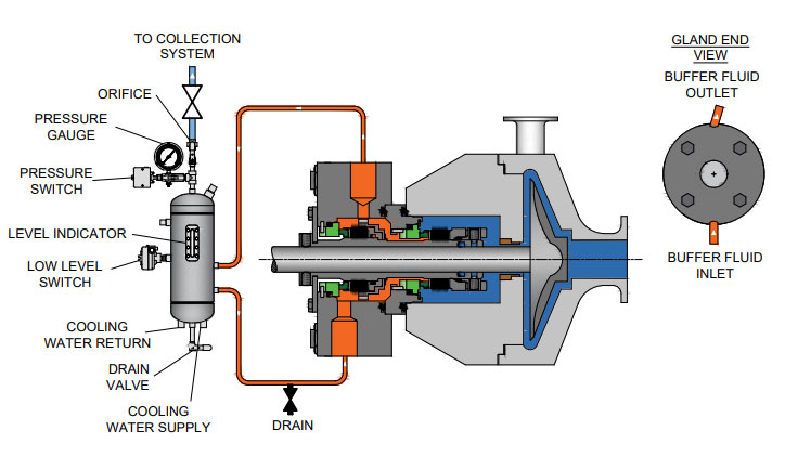
BSS Buffer Support System Plan 52 Non-Pressurized Tank Easy to install, complete non-pressurized solution for reliable operation of dual mechanical seals. The Chesterton Buffer Support System (BSS) for dual mechanical seals is a complete solution for the environmental support of dual mechanical seals where product contamination from support fluid cannot be tolerated. BSS Configuration Supplied ready to install the BSS is preconfigured to allow simple connection and non-pressurized support to a dual mechanical seal. A dedicated fill valve allows quick and easy commissioning of the seal and...
Operating Principle The support fluid is circulated by thermosyphon effect or the mechanical seal’s pumping ring. Connect the system to the seal and add the support fluid via the fill valve until it is at the required level on the glass. 4 Drain Valve 5 Auxiliary Connections Ordering Codes Type Item Number Buffer Support System complete with all the Components Buffer Support System complete with Cooling Coil Tank Stands Telescopic Vertically and Horizontally Adjustable Stand - Stainless Steel Piping Kits Fixed Stand - Stainless Steel Telescopic Vertically and Horizontally Adjustable Stand -...
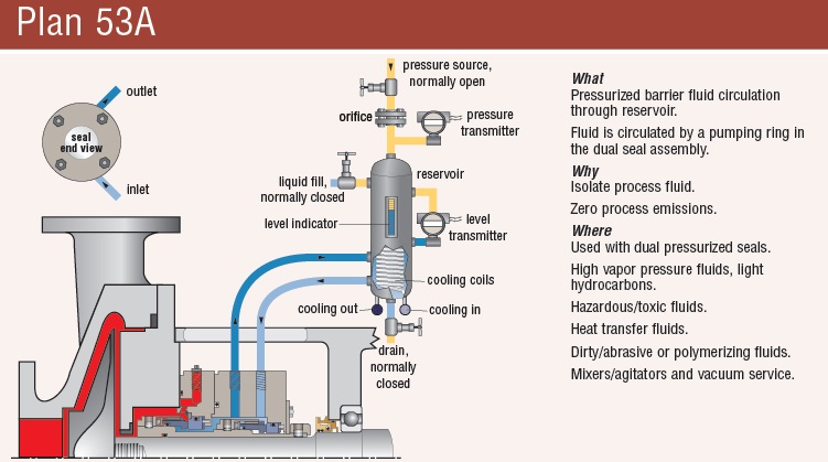
PSS Pressurized Support System Plan 53A Standard Tank Easy to install, complete pressurized solution, for reliable operation of dual mechanical seals. The Chesterton Pressurized Support System (PSS) for dual mechanical seals is a complete solution for the support of dual mechanical seals where product leakage cannot be tolerated. Pressurized Support System Configuration Supplied ready to install, the PSS features a non-return valve, pressure regulator with gauge, and pressure relief valve. A dedicated fill valve allows quick and easy commissioning of the seal and system arrangement. The PSS...
Operating Principle Close the fill valve and connect the air or nitrogen supply and adjust the regulator to the required pressure. Connect the system to the seal and add the support fluid via the fill valve until it is at the required level on the glass. The barrier fluid is circulated by thermosyphon effect or the mechanical seal’s pumping ring. Mounting Brackets Ordering Codes Type Item Number Pressurized Support System complete with the Components Pressurized Support System complete with Cooling Coil Fixed Stand - Stainless Steel Telescopic Vertically and Horizontally Adjustable Stand -...
Flow Guardian Plan 32/33S/54DM Specifically designed to supply uninterrupted, regulated seal flush water and deliver operational efficiency to the pump population. Managing flow rates while regulating important pressure differentials is possible. Costly seal failures are reduced while assisting in-plant water conservation initiatives. Flow Guardian Selection There is a Flow Guardian for every application. The DP50 Dual Flow Guardian is designed to measure flow entering and exiting a dual seal installation. This capability allows for early detection of leakage into the process stream as a...
Water Saver Features a thermally activated valve that automatically drains hot barrier fluid (only when necessary) to keep dual seals running cool and reliable. Valve opening temperature preset to work with S20 Seals. 95% water savings compared to open barrier fluid supply Recommended Applications Technical Data Chemical industry Pulp and paper industry Operating Parameters Pressure Limit Temperature Limit Temperature Set Point Connections 20.7 bar g / 300 psig* 125°C / 257°F 80°C / 176°F 1/4" NPT Materials of Construction Body Bushing Hose Barb Fitting 303 Stainless Steel / EN 1.4305 316...

Mechanical seals are indispensable for sealing rotating shafts. They make sure that the fluid handled remains in the system, prevent emissions and thus protect the environment from contamination. High-quality shaft seals in the form of mechanical seals also ensure maximum economic efficiency and operating reliability for pumps. This is crucial because the majority of repairs arise due to sealing problems.
And this is where KSB’s mechanical seals can make a difference: as well as impressing with a robust design, they offer straightforward installation and optimal integration in the seal chamber – ensuring reliable and efficient system operation.
A singlemechanical seal consists of two very flat seal faces that are forced together by a spring and slide against one another. Between these two faces is a thin fluid film generated by the process fluid or pumped product. This fluid film (typically gap of 1 micron or 75 times narrower than a human hair), lubricates and cools the seal. An absence of this thin fluid film (pump running dry or product flashing) results in frictional heat and ultimately the destruction of the mechanical seal.
The sealed fluid typically enters the gap between the seal faces as a liquid. As it migrates across the seal faces from the high-pressure side to the atmosphere, its pressure drops, and temperature rises. The liquid may vaporize so there may be no visible liquid leakage. A correctly specified seal operating properly will typically meet VOC emissions standards.
A dual mechanical seal consists of two seals arranged in a series. The inboard seal keeps the product contained within the pump housing. The outboard seal prevents the barrier or buffer liquid from getting into the atmosphere.
Double Seal: With barrier fluid pressure higher than product pressure the seal prevents leakage of toxic or hazardous fluids into the environment. The barrier fluid provides lubrication to seal gasses and non-lubricating fluids.
Tandem Seal: By using a buffer fluid with pressure to lower than process, the seal can reduce the pressure differential across a single set of seal faces.
Spare Seal: With unpressurized buffer fluid the outboard seal operates “at idle” as a standby seal. If the inboard seal fails, the outboard seal provides primary protection, eliminating unscheduled shutdown of batch processes.
Slurry mechanical seal as a simple "pre-set cartridge seal" that requires no measuring or special tools for assembly into the equipment housing easily disassembled and rebuilt either in the field or plant workshop, without the need of any special tools.
Sealing many products in various types of fluid handling equipment WITHOUT any type of flush thereby eliminating product dilution or contamination from barrier fluids or gases. (Some services a flush has been shown to prolong seal life).
Optimum sealing performance while running totally submerged, but to also withstand intermittent dry running situations, and still maintain a positive seal when the fluid returns to the seal area.
Design features have minimized the number of parts facilitating ease of assembly and installation. Fewer o-rings than other slurry seals reducing the number of possible leak paths.
Minimum amount of spares for inventory, thereby minimizing inventory carry costs and freeing up shelf space. (Traditional mechanical seals are sold in 1/8 in. increments. One PANACEAL compared to eight traditional seals).
No seal hang-up due to product crystallization on the atmospheric side of the rotary assembly. (Product crystallization is a normal result of face lubrication).
Not only do we handle all styles of seals and environmental controls, we can also repair, modify and even build what you need when standard products don’t do the job. We repair all brands in-house.
We have developed a very powerful root-cause failure analysis capability to identify what is really going on in your pumps. We “follow the evidence” like CSI. From legitimate and reliable analysis, we can identify the cause or causes of premature failure, recommend the solution and provide it without long lead times or ridiculous prices.
We just don"t know of another company that can do so much for you in the murky world of mechanical seals. With our training programs, we can even make the murkiness go away.
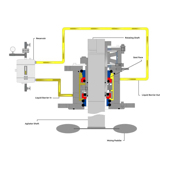
The family of shaft seals known as mechanical seals is the most advanced type of seal used in the mixing industry. They can handle the highest pressures, maintain nearly leak-free operation, and require minimum maintenance if installed and operated properly. The downside is the higher initial cost (both for the seal and for the more complicated equipment required surrounding the seal) and the expertise needed to service the seals. Mechanical seals are increasing in popularity due to the growing environmental restrictions regarding any leakage from process tanks.
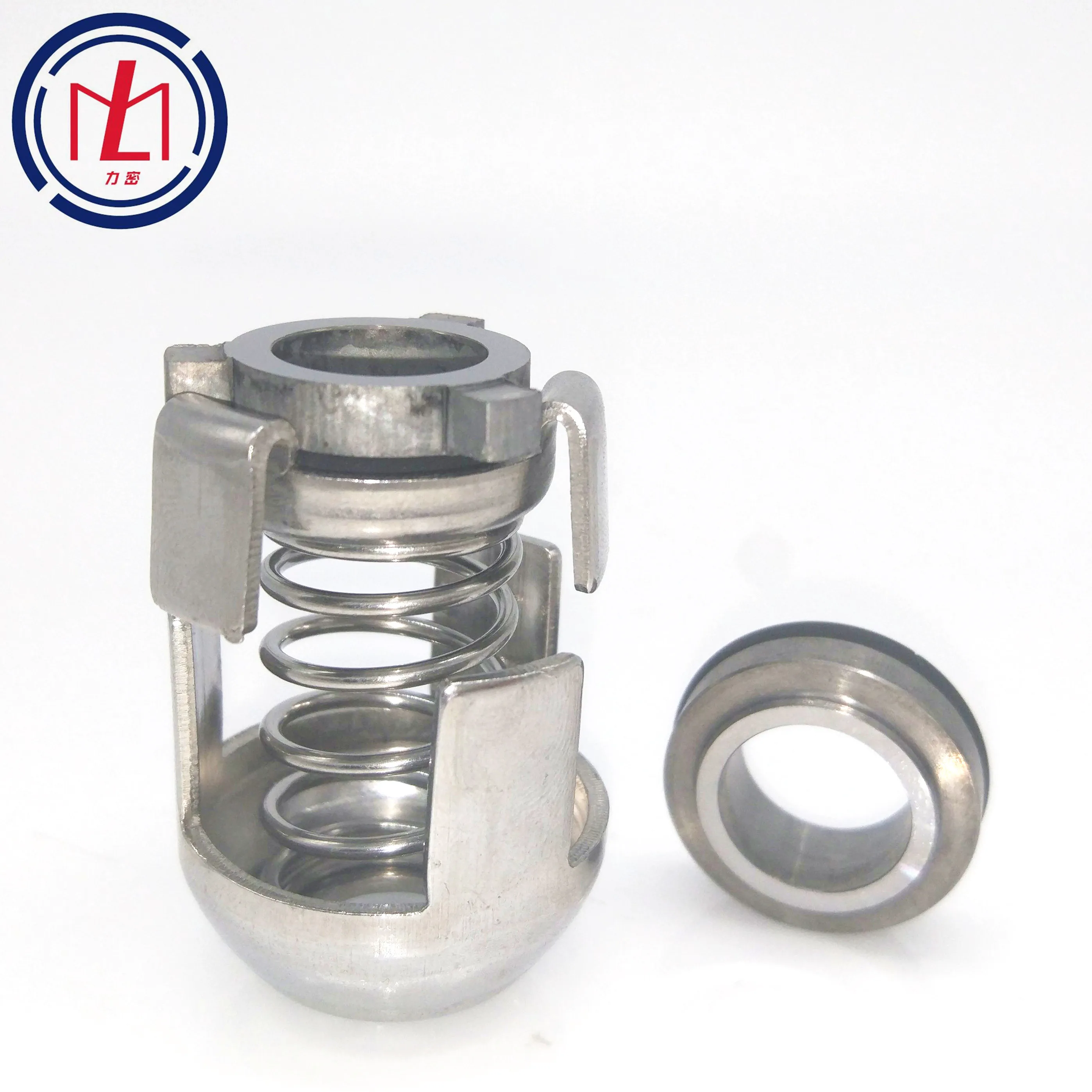
There are hundreds of mechanical seal designs, but they all are variations of a basic layout consisting of a collar mounted on the shaft which uses springs to push a ring (which also rotates with the shaft) against another ring that is held stationary. The rings rotate against each other riding on a thin layer of lubricant, and the springs hold them so tightly together that leakage through the seal is reduced to an immeasurable amount. The mating surfaces of the rings must be perfectly flat to seal properly, and are manufactured to tolerance measured “light- bands." The rings must also be extremely hard to endure the pressure and wear, so they are usually made up of ceramic, carbon, silicon carbide, tungsten carbide or similar materials. The stationary “seat” is held in place and maintains a static seal with the mounting housing using gaskets or o-rings. The rotating elements of the seal must attain a static seal with the shaft using o-rings, wedges or packing.

DuraClear Crystal 7 Seal Lubricant is a premium barrier fluid for use on equipment handling high purity, high value or highly reactive product fluids such as strong acids and bases. It has been specifically formulated for the lubrication needs of dual mechanical seals. When chemical compatibility is critical, this environmentally friendly and nonreactive barrier fluid extends the life of dual mechanical seals for increased process yield and throughput.
CTFE fluids may react violently with K, Na, amine, hydrazine, liquid fluorine, liquid chlorine trifluoride, Aluminum, Aluminum Chloride (AlCl3) and Aluminum Oxide (Al2O3)
This website is using a security service to protect itself from online attacks. The action you just performed triggered the security solution. There are several actions that could trigger this block including submitting a certain word or phrase, a SQL command or malformed data.

As end users face increasingly restrictive leakage and safety regulations, a growing number are turning to multiple seal arrangements. Multiple sealing arrangements require a liquid or gas buffer or barrier fluid to operate, introducing a new factor that end users must monitor.
Below are some best practices for liquid buffer and barrier fluids. By selecting an appropriate fluid and following proper maintenance procedures, end users can promote system reliability and extend their systems’ operating lives.
In addition to process fluid, all multiple seals use an external fluid. Depending on the sealing arrangement, this external fluid is called buffer fluid or barrier fluid. American Petroleum Institute (API) Standard 682 specifies that unpressurized dual seals, also known as traditional tandem seal arrangements, use buffer fluid. Pressurized dual seals, on the other hand, use barrier fluid, which isolates the pump process liquid from the rest of the system.
When selecting a fluid, end users should weigh the pros and cons of their applications. Some common barrier and buffer fluids, which have benefits and potential risks, are:
Glycol solutions — These, which usually contain 50 percent ethylene glycol and 50 percent water, are the simplest and most common barrier or buffer fluids. Because inhibitors can come out of the solution and damage the seal faces, end users should use uninhibited glycol in these solutions instead of glycol with inhibitors, such as antifreeze. Since some areas restrict the use of ethylene glycol, end users may need to use propylene glycol instead.
Petroleum-based hydraulic, conventional gear and bearing lubricating oils — Because they are widely available, they are popular choices. However, the viscosity of these oils can cause carbon seal face blistering, particularly with oils that are Grade 32 or higher on the International Organization for Standardization (ISO) scale.
Synthetic oils specifically formulated for barrier or buffer use — These have grown increasingly popular during the last decade. These synthetics are typically polyalphaolefin-based, and they range between ISO Grade 5 and Grade 20 (approximately). Lower-viscosity synthetics are the most popular option among end users. Higher-viscosity synthetics, which are more expensive, are the best choice for applications with high temperatures or low shaft speeds.
Heat transfer fluids — Although useful in extremely high-temperature services, these fluids can pose problems because they tend to decompose and form coke, or hard carbon formations.
After choosing the correct fluid for their system, end users must maintain the fluid and the sealing environment properly to ensure peak performance. Checking the fluid each month for changes in pH, color, viscosity, consistency and the presence of solids is a good way to help promote system reliability.
While users should change their barrier and buffer fluids regularly, service life can vary dramatically. In general, fluids operating at high temperatures need changing more frequently than those at lower temperatures.
According to API 682, the allowable temperature rise is 15° F for systems with buffer or barrier fluids that are water-based, diesel or kerosene, and 30° F for systems that use mineral or synthetic oil as buffer or barrier fluids. For example, a system using oil could have an average reservoir temperature of 130° F with an outlet temperature of 115° F and an inlet temperature of 145° F.
When monitoring the decomposition of buffer or barrier fluids, end users should consider this rule of thumb for chemical reactions — the rate of reaction doubles for every 18 F rise in temperature. For example, if a barrier fluid needs changing every six months at an average reservoir temperature of 130° F, the same fluid would need to be changed every three months if the reservoir temperature is 148° F. This simple guideline can be useful for evaluating heat transfer options during system design.
In addition to temperature considerations, buffer fluids can become contaminated by the process liquid and may require more frequent changing than barrier fluids.
While selecting the proper buffer and barrier fluid is an important first step toward sealing system reliability, the following considerations also have a big effect on performance:
API 682 provides useful guidelines and default selections for standardized dual seal systems — including Piping Plans 52, 53A/B/C and 54. By combining the API guidelines with the best practices for buffer and barrier fluids described in this article, end users can keep their systems operating smoothly.
As operators of pumping equipment become more focused on the safety, reliability and environmental impact resulting from shaft seal leakage, dual mechanical seals have become more prevalent in the industry. A dual mechanical seal offers a second (outer) seal to contain the pumped fluid by creating a cavity or chamber between the inner and outer seal that can be filled with a fluid. When this fluid is unpressurized, it forms a buffer between the pumped fluid and atmosphere and is commonly referred to as a buffer fluid. When pressurized, it forms a barrier between the pumped fluid and atmosphere and is known as a barrier fluid.
Although mechanical seal designs are available in configurations that use either a liquid or a gas as a barrier fluid, the following discussion focuses on liquid buffer and barrier fluids only. In addition to separating the pumped fluid from the atmosphere, liquid buffer and barrier fluids lubricate the mechanical seal and transport frictional heat and absorbed heat from the mechanical seal to a heat exchanger. This controls the fluid’s temperature and lubricating properties.
Buffer/barrier fluid can be stored, monitored and delivered using many methods. Each is identified by a piping plan number that describes the minimum requirements of each system. The most commonly referenced piping plan originates from the American Petroleum Institute’s standard API 682.
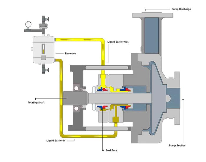
A Plan 52 system (see Figure 1) provides a reservoir that stores the buffer fluid. Supply and return lines are connected to the mechanical seal and circulation of the buffer fluid is achieved by an internal circulating device (pumping ring) within the mechanical seal. The vapor space above the buffer fluid in the reservoir is vented to atmospheric pressure typically via a flare or vapor recovery system. The reservoir can be instrumented to measure the liquid level and pressure in the reservoir. Ports are fitted to the reservoir to facilitate maintenance activities—such as inspection and cleaning or refilling and draining the buffer fluid. Cooling is accomplished using an internal heat exchanger.
Pressurized dual seal systems contain the same essential components as an unpressurized system. However, they also contain a way to pressurize the barrier fluid. The following plans may be used for pressurized dual seal systems:
Plan 53A—A pressurized gas blanket in the reservoir pressurizes the fluid. Nitrogen is normally used and the pressure is controlled via a pressure regulator (see Figure 2). The barrier fluid is in direct contact with the pressurized gas.
Plan 53B—Pressure is generated as a nitrogen-filled bladder is compressed by the addition of barrier fluid into the bladder accumulator. The bladder prevents direct contact of the pressurized gas with the barrier fluid.
Plan 53C—A pressure amplifying piston uses pressure from within the pump (typically the seal chamber) to amplify the barrier pressure by the ratio of the area on each side of the piston. The barrier fluid is not exposed to any pressurized gas.
Plan 54—An external system is used to pressurize and circulate the barrier fluid. A Plan 54 system can be broadly classified into two groups: closed- and open-loop systems. In closed-loop systems, the barrier fluid is stored in a large reservoir and pumps pressurize and circulate the fluid. In open-loop systems, a compatible process stream is used as the barrier fluid and is circulated through the mechanical seal and returned to another point downstream in the process.
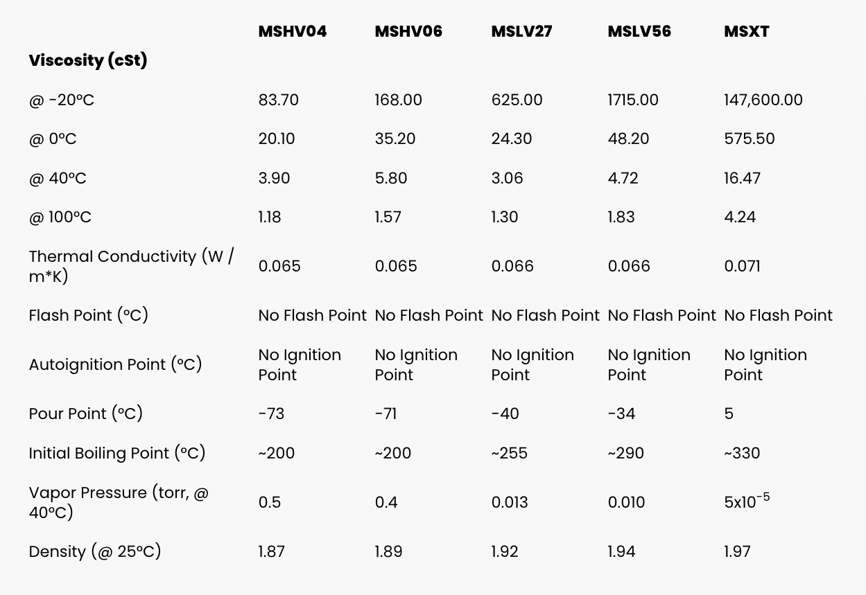
Several critical properties of a buffer or barrier fluid must be considered when making a selection. An ideal buffer or barrier fluid will have the following properties:
Water offers several benefits as a buffer/barrier fluid. Its thermal conductivity is about three times greater than oils and its specific heat is about twice that of oils, so it is good at transporting heat away from a mechanical seal. Water is inexpensive, easy to handle and store, has few seal material compatibility issues and is nonflammable. It is also compatible with many aqueous pumped solutions. Its viscosity is generally around 1 centistoke at moderate temperatures which offers low resistance to flow in the barrier system.
However, the viscosity becomes low at elevated temperatures limiting its effectiveness as a lubricant for the mechanical seal faces. Water is also susceptible to freezing during the winter months. This results in a narrow window of service and environment temperatures in which water can be used.
Generally, oils can be used in a much wider range of service temperatures. Compared to water, oils offer greater fluid stability at elevated temperatures and are not susceptible to freezing. They also provide excellent lubrication of the mechanical seal faces and, therefore, have the potential to offer longer seal life. Few compatibility issues with mechanical seal materials exist.
Oils are available in a wide range of types, compositions and viscosities. Traditional oils used in the industry include turbine oils and automatic transmission fluids. However, performance as buffer and barrier fluids has not been as successful as other oils, primarily because of the complex mixture of additives in these fluids.
Good performance can be achieved from oils with viscosity below that of ISO Grade 32 oils. High viscosities can result in damage to the mechanical seal faces, particularly when carbon is used as a face material. Paraffinic-based oils also generally perform better than naphthenic oils while synthetic oils offer even better performance. Synthetic lubricants specifically developed for use as a buffer/barrier fluid are now available in the marketplace and offer excellent performance. However, this performance is achieved at the sacrifice of cost.
We invite your suggestions for article topics as well as questions on sealing issues so we can better respond to the needs of the industry. Please direct your suggestions and questions to sealingsensequestions@fluidsealing.com.

This website is using a security service to protect itself from online attacks. The action you just performed triggered the security solution. There are several actions that could trigger this block including submitting a certain word or phrase, a SQL command or malformed data.

Barrier Fluid FDA is a pure, non-reactive, synthetic fluid that provides superior lubrication and cooling for double and tandem mechanical seals. Barrier Fluid FDA provides very stable seal performance over an extremely wide temperature range, satisfying most seal service requirements. Barrier Fluid FDA is extremely clean and has excellent low temperature fluidity and heat transfer properties. Barrier Fluid FDA is sanctioned under the FDA CFR Title 21 Sections 178.3620(a)(b); 172.878; 175.105; 176.200 and 210; 177.2260, 2600 and 2800; 178.3570 and 3910. It is NSF Certified for H1 service. Barrier Fluid FDA is essentially inert, allowing it to be used with most hydrocarbon gases and aqueous acids and bases. Barrier Fluid FDA is an undyed product.


 8613371530291