
barrier fluid in mechanical seal for sale

Lubriplate Barrier Fluids are ultra-clean, polyalphaolefin (PAO) synthetic based fluids recommended for all types of mecahnical seals. While they are NSF H1 registered food grade, they may be used for all applications requiring barrier fluid for mechanical seals.

This website is using a security service to protect itself from online attacks. The action you just performed triggered the security solution. There are several actions that could trigger this block including submitting a certain word or phrase, a SQL command or malformed data.

Buffer / barrier fluid for mechanical seals. A pure, non-reactive, synthetic fluid that provides superior lubrication and cooling for double and tandem mechanical seals.
Buffer / barrier fluid for double and tandem mechanical seals. Recommended for use at elevated temperatures where a nitrogen purge is not an option and when FDA purity is not required.
DuraClear Crystal 7 Seal Lubricant is a premium barrier fluid for use on equipment handling high purity, high value or highly reactive product fluids such as strong acids and bases. It has been specifically formulated for the lubrication needs of dual mechanical seals. When chemical compatibility is critical, this environmentally friendly and nonreactive barrier fluid extends the life of dual mechanical seals for increased process yield and throughput.
CTFE fluids may react violently with K, Na, amine, hydrazine, liquid fluorine, liquid chlorine trifluoride, Aluminum, Aluminum Chloride (AlCl3) and Aluminum Oxide (Al2O3)
Barrier Fluid FDA is a pure, non-reactive, synthetic fluid that provides superior lubrication and cooling for double and tandem mechanical seals. Barrier Fluid FDA provides very stable seal performance over an extremely wide temperature range, satisfying most seal service requirements. Barrier Fluid FDA is extremely clean and has excellent low temperature fluidity and heat transfer properties. Barrier Fluid FDA is sanctioned under the FDA CFR Title 21 Sections 178.3620(a)(b); 172.878; 175.105; 176.200 and 210; 177.2260, 2600 and 2800; 178.3570 and 3910. It is NSF Certified for H1 service. Barrier Fluid FDA is essentially inert, allowing it to be used with most hydrocarbon gases and aqueous acids and bases. Barrier Fluid FDA is an undyed product.
This website is using a security service to protect itself from online attacks. The action you just performed triggered the security solution. There are several actions that could trigger this block including submitting a certain word or phrase, a SQL command or malformed data.
Chesterton 662 FG is an ISO VG Grade 22 high-performance lubricant designed specifically as a barrier fluid for double mechanical seal applications. 662 FG is suitable for all industrial and food/beverage/pharmaceutical applications. 662 FG is NSF H1 registered.
The ultra-clean 662 FG delivers premium thermal stability while minimizing the abrasive-particle wear of the seal faces and extending equipment life.
Wenzhou Landmark Seal Manufactuing Co,.Ltd is established in 2011, Producing small standard mechanical seals with quantity more than 250000 pcs per month. Our advantage is small seals with all range of stamping and rubber moulds. The production is ISO 9001 , TUV , SGS, ROHS certificated.
Tegra Synthetic Barrier Fluid is designed to meet the needs of a barrier fluid for dual mechanical seals per API Standard 682, Shaft Sealing Systems for Centrifugal and Rotary Pumps. Dual mechanical seals are used to control emissions of volatile air pollutants from industrial equipment. Leading seal manufacturers recommend the use of low viscosity synthetic fluids for extended seal life of API Standard 682 dual mechanical seals.
Tegra Synthetic Barrier Fluid 17 cSt has a low Volatile Organic Compound (VOC) level, so that the barrier fluid itself will not be the source of volatile air pollutants in higher temperature applications.

Our barrier seal reservoirs are built to ASME Section VIII standards and ASME U code stamps are available. All our barrier fluid systems, whether custom or standard designs are designed and built to the current API 682 requirements.

Protect the integrity, efficiency, and flow of your site operations with help from AFT. No matter the size or complexity or your system, AFT and our partner AESSEAL offer the highest quality seals and support systems for your industry.

AfghanistanÅland IslandsAlbaniaAlgeriaAmerican SamoaAndorraAngolaAnguillaAntarcticaAntigua & BarbudaArgentinaArmeniaArubaAustraliaAustriaAzerbaijanBahamasBahrainBangladeshBarbadosBelarusBelgiumBelizeBeninBermudaBhutanBoliviaBosnia & HerzegovinaBotswanaBouvet IslandBrazilBritish Indian Ocean TerritoryBritish Virgin IslandsBruneiBulgariaBurkina FasoBurundiCambodiaCameroonCanadaCape VerdeCaribbean NetherlandsCayman IslandsCentral African RepublicChadChileChina (mainland)Christmas IslandCocos (Keeling) IslandsColombiaComorosCongo - BrazzavilleCongo - KinshasaCook IslandsCosta RicaCôte d’IvoireCroatiaCubaCuraçaoCyprusCzechiaDenmarkDjiboutiDominicaDominican RepublicEcuadorEgyptEl SalvadorEquatorial GuineaEritreaEstoniaEswatiniEthiopiaFalkland IslandsFaroe IslandsFijiFinlandFranceFrench GuianaFrench PolynesiaFrench Southern TerritoriesGabonGambiaGeorgiaGermanyGhanaGibraltarGreeceGreenlandGrenadaGuadeloupeGuamGuatemalaGuernseyGuineaGuinea-BissauGuyanaHaitiHeard & McDonald IslandsHondurasHong KongHungaryIcelandIndiaIndonesiaIranIraqIrelandIsle of ManIsraelItalyJamaicaJapanJerseyJordanKazakhstanKenyaKiribatiKuwaitKyrgyzstanLaosLatviaLebanonLesothoLiberiaLibyaLiechtensteinLithuaniaLuxembourgMacao SAR ChinaMadagascarMalawiMalaysiaMaldivesMaliMaltaMarshall IslandsMartiniqueMauritaniaMauritiusMayotteMexicoMicronesiaMoldovaMonacoMongoliaMontenegroMontserratMoroccoMozambiqueMyanmar (Burma)NamibiaNauruNepalNetherlandsNew CaledoniaNew ZealandNicaraguaNigerNigeriaNiueNorfolk IslandNorth KoreaNorth MacedoniaNorthern Mariana IslandsNorwayOmanPakistanPalauPalestinian TerritoriesPanamaPapua New GuineaParaguayPeruPhilippinesPitcairn IslandsPolandPortugalPuerto RicoQatarRéunionRomaniaRussiaRwandaSamoaSan MarinoSão Tomé & PríncipeSaudi ArabiaSenegalSerbiaSeychellesSierra LeoneSingaporeSint MaartenSlovakiaSloveniaSolomon IslandsSomaliaSouth AfricaSouth Georgia & South Sandwich IslandsSouth KoreaSouth SudanSpainSri LankaSt. BarthélemySt. HelenaSt. Kitts & NevisSt. LuciaSt. MartinSt. Pierre & MiquelonSt. Vincent & GrenadinesSudanSurinameSvalbard & Jan MayenSwedenSwitzerlandSyriaTaiwanTajikistanTanzaniaThailandTimor-LesteTogoTokelauTongaTrinidad & TobagoTunisiaTurkeyTurkmenistanTurks & Caicos IslandsTuvaluU.S. Outlying IslandsU.S. Virgin IslandsUgandaUkraineUnited Arab EmiratesUnited KingdomUnited StatesUruguayUzbekistanVanuatuVatican CityVenezuelaVietnamWallis & FutunaWestern SaharaYemenZambiaZimbabwe
As end users face increasingly restrictive leakage and safety regulations, a growing number are turning to multiple seal arrangements. Multiple sealing arrangements require a liquid or gas buffer or barrier fluid to operate, introducing a new factor that end users must monitor.
Below are some best practices for liquid buffer and barrier fluids. By selecting an appropriate fluid and following proper maintenance procedures, end users can promote system reliability and extend their systems’ operating lives.
In addition to process fluid, all multiple seals use an external fluid. Depending on the sealing arrangement, this external fluid is called buffer fluid or barrier fluid. American Petroleum Institute (API) Standard 682 specifies that unpressurized dual seals, also known as traditional tandem seal arrangements, use buffer fluid. Pressurized dual seals, on the other hand, use barrier fluid, which isolates the pump process liquid from the rest of the system.
When selecting a fluid, end users should weigh the pros and cons of their applications. Some common barrier and buffer fluids, which have benefits and potential risks, are:
Glycol solutions — These, which usually contain 50 percent ethylene glycol and 50 percent water, are the simplest and most common barrier or buffer fluids. Because inhibitors can come out of the solution and damage the seal faces, end users should use uninhibited glycol in these solutions instead of glycol with inhibitors, such as antifreeze. Since some areas restrict the use of ethylene glycol, end users may need to use propylene glycol instead.
Petroleum-based hydraulic, conventional gear and bearing lubricating oils — Because they are widely available, they are popular choices. However, the viscosity of these oils can cause carbon seal face blistering, particularly with oils that are Grade 32 or higher on the International Organization for Standardization (ISO) scale.
Synthetic oils specifically formulated for barrier or buffer use — These have grown increasingly popular during the last decade. These synthetics are typically polyalphaolefin-based, and they range between ISO Grade 5 and Grade 20 (approximately). Lower-viscosity synthetics are the most popular option among end users. Higher-viscosity synthetics, which are more expensive, are the best choice for applications with high temperatures or low shaft speeds.
Heat transfer fluids — Although useful in extremely high-temperature services, these fluids can pose problems because they tend to decompose and form coke, or hard carbon formations.
After choosing the correct fluid for their system, end users must maintain the fluid and the sealing environment properly to ensure peak performance. Checking the fluid each month for changes in pH, color, viscosity, consistency and the presence of solids is a good way to help promote system reliability.
While users should change their barrier and buffer fluids regularly, service life can vary dramatically. In general, fluids operating at high temperatures need changing more frequently than those at lower temperatures.
According to API 682, the allowable temperature rise is 15° F for systems with buffer or barrier fluids that are water-based, diesel or kerosene, and 30° F for systems that use mineral or synthetic oil as buffer or barrier fluids. For example, a system using oil could have an average reservoir temperature of 130° F with an outlet temperature of 115° F and an inlet temperature of 145° F.
When monitoring the decomposition of buffer or barrier fluids, end users should consider this rule of thumb for chemical reactions — the rate of reaction doubles for every 18 F rise in temperature. For example, if a barrier fluid needs changing every six months at an average reservoir temperature of 130° F, the same fluid would need to be changed every three months if the reservoir temperature is 148° F. This simple guideline can be useful for evaluating heat transfer options during system design.
In addition to temperature considerations, buffer fluids can become contaminated by the process liquid and may require more frequent changing than barrier fluids.
While selecting the proper buffer and barrier fluid is an important first step toward sealing system reliability, the following considerations also have a big effect on performance:
API 682 provides useful guidelines and default selections for standardized dual seal systems — including Piping Plans 52, 53A/B/C and 54. By combining the API guidelines with the best practices for buffer and barrier fluids described in this article, end users can keep their systems operating smoothly.
Mechanical seals are designed to prevent leakage of fluid from centrifugal pumps that support industrial processes. Mechanical seals depend on mechanical seal support systems for reliable operations. I’ve provided information below to help explain mechanical seal support basics. I’m hopeful it’ll help you gain a better understanding of mechanical seals and the various types of mechanical seal support systems, their applications, and optional configurations to help boost reliability in your Northern California Bay Area refinery.
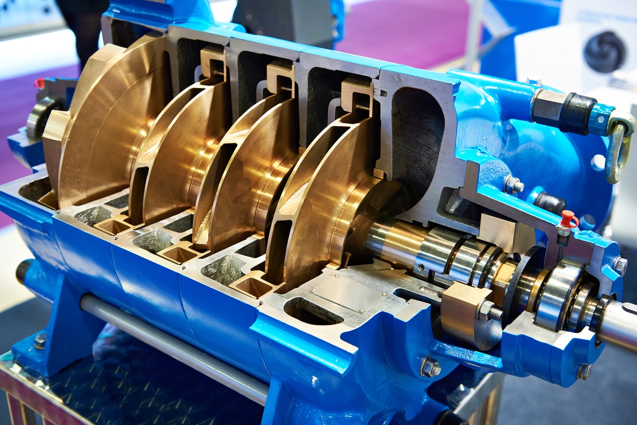
A mechanical seal is used to contain fluid within a centrifugal pump where the impeller shaft passes through a stationary housing. There’s a range of mechanical seal designs to cover every conceivable pumping process. Low to high pressure, low to high fluid temperatures, clean plant water to heavy hydrocarbons. To cover that wide range of pumping processes and conditions there’s an equally wide range of seal support systems and custom configurations to match the need.
At its simplest, a mechanical seal support system is designed to provide the proper seal chamber environment to maintain the integrity of the mechanical seal. The system provides cooling and lubrication to reduce mechanical seal friction and heat and prevent leakage. To accomplish this, mechanical seal support systems deliver process fluid, water, oil, or inert gas to the seal chamber at the required pressure, temperature, and flow.
Maintaining the proper seal chamber environment prevents leakage that could lead to loss of profitable products, degradation of pumps and their supporting infrastructure, or in the worst cases, conditions that pose environmental risk and subject you to Cal/OSHA and BAAQMD sanctions.
Centrifugal pumps and mechanical seal support systems are critical to the petroleum industry. As a result, the American Petroleum Institute has developed a standard to describe the different seal support systems, known as piping plans. See API Standard 682: Pumps—Shaft Sealing Systems for Centrifugal and Rotary Pumps for a listing of the various plans. The complete document is over 250 pages, but below I"ve distilled the document into a greatly simplified overview of mechanical seal support basics.
Mechanical seal support systems can be grouped into three categories—process side, dual or in-between, and atmospheric side. Let me explain the basics of these categories by describing the type of mechanical seal, the typical pumping applications, and the various API plans that provide the required environment for the mechanical seal and pumping conditions.
Process side mechanical seal support systems provide the lubrication and cooling to a single mechanical seal to keep process fluid within the pump volute. Process fluid is used for lubrication and cooling in three ways: it is circulated from the discharge to seal chamber, from the seal chamber to the suction, or from discharge to seal chamber and then to suction. Alternatively, a flush fluid that provides lubrication and cooling can be delivered from a reservoir which is part of the seal support system or an external source, such as plant water.
This single-seal solution is used when the pumped fluid poses no environmental threat in the event that the pumped fluid vaporizes as it crosses the seal faces and dissipates into the atmosphere. The table below summarizes the API Plans in the process side category, indicates the types of fluids used to provide cooling and lubrication, and the components that differentiate the plans and their capabilities.
Process side mechanical seal support systems cover a range of pumping processes, from clean, moderate-temperature, non-polymerizing fluids to high-temperature dirty or contaminated fluids. Cooling and filtering options enable these plans to remove contaminants that would damage seal faces. Pumping applications can include:
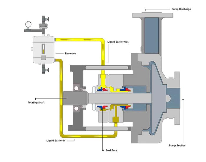
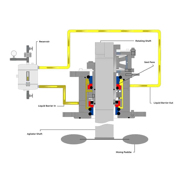
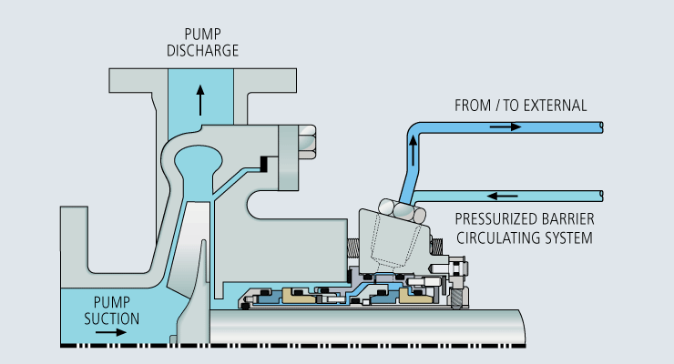
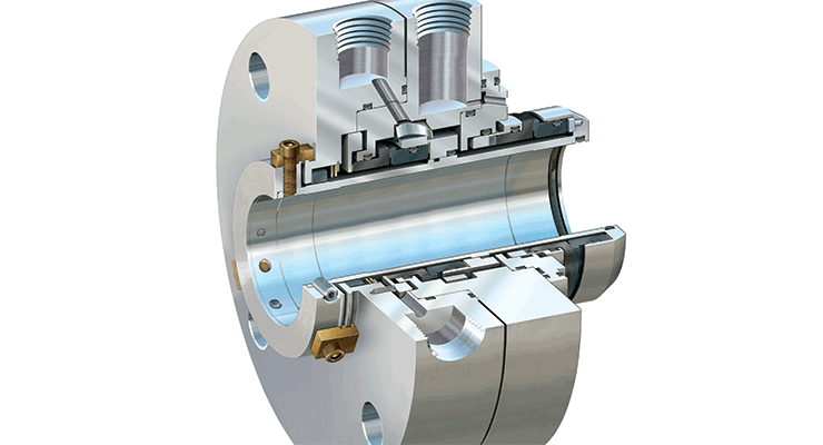
Dual or in-between mechanical seal support systems deliver a buffer (unpressurized) or barrier (pressurized) fluid to a seal chamber that contains a double mechanical seal—two seals arranged in series to maintain the buffer/barrier fluid between the two seals. The inboard (primary seal) keeps process fluid within the pump housing. The outboard (secondary seal) prevents the buffer/barrier fluid from leaking to the atmosphere. The buffer/barrier fluids that lubricate the seal faces and dissipate heat can be gas or liquid.
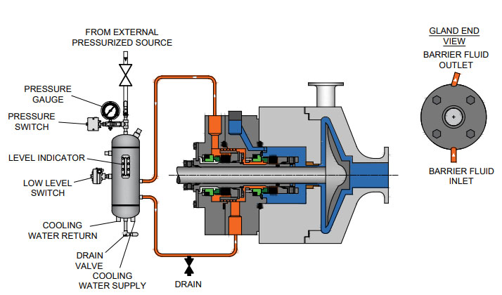
Pressurization of barrier fluid is provided by plant nitrogen, bladder accumulator, piston accumulator for API Plans 53A, 53B, and 53C respectively. Plan 54 is pressurized by the external pump. Plan 72 buffer fluid is plant nitrogen.
Atmospheric side mechanical seal support systems deliver an unpressurized fluid (also known as a “quench”) to the atmospheric side (exposed to air) of a mechanical seal. This method is used when a single mechanical seal cannot operate properly without the aid of the quench. In comparison to the process side and dual seal support systems, there are only two variants:
API Plan 62 - Quench From External Source delivers clean water, low-pressure steam, or nitrogen to cool the seal faces and prevent oxidation or coking of process fluid.
Our brief explanation of mechanical seal support system basics shows you the wide range of capabilities and applications. There’s a solution for every type of pumping process. You don’t need an in-depth understanding to obtain the maximum benefit from a mechanical seal support system if you work with a local vendor in the Northern California Bay Area who has deep industry experience.
In addition to knowing which mechanical seal support system is best for a specific pumping process, a local vendor who conducts an on-site evaluation is able to make specific recommendations regarding system design, instrumentation, and components to boost pump reliability. Fabricated and thoroughly tested in Swagelok’s Fremont, Santa Clara, or Concord facility, you’ll have a mechanical seal support solution custom-configured to the specific requirements of your pumping process.
Swagelok Northern Californiawill be happy to explain mechanical seal support basics and advise you on the specific plans to improve pump reliability. To arrange an on-site consultation by one of our Field Engineerscontact our teamtoday by calling
Rotating equipment engineers are responsible for avoiding unplanned downtime and making sure pumps are online and operational. As fluid system experts, Swagelok supports those responsibilities by designing and building seal support systems that are reliable, easy to maintain, and safe to operate. Our easy-to-configure, locally built, and reliable solutions help you reduce costs, save time, and improve safety.
Swagelok"s API 682 standard designs incorporate all the recommended components and adhere to best practices. For better operation and service of the seal and pump, we go beyond the standards to design systems specific to your application. This includes optional isolation valves, bypass loops, and instrumentation to assist the pump operator in both maintaining the system and monitoring the health of the seal.
Swagelok mechanical seal support systems are designed and built by your local authorized sales and service center how you want them and when you need them.
Swagelok’s fluid system expertise leverages design practices that maximize your seal support system’s operation and safe maintenance. And Swagelok products are backed by our Limited Lifetime Warranty.
Proper system start-up and commissioning are critical for the reliable operation of mechanical seals and their associated support systems. Inclusion of air within the system at start-up can lead to issues with the seal support system. Flow can be disrupted or stopped in systems with chillers or seal pots. Air inclusions can also prevent the support system from providing the desired rate of cooling. Swagelok design options include high-point vents in the seal support system, allowing the system to be vented and cleared of entrapped air.
System maintenance during turnarounds and projects requires seal support systems to be drained for servicing. When taking a pump out of service, including low point drains allows the system to be purged of buffer, barrier, or flush fluids, quickly and safely.
Pressure and temperature measurement devices help plant personnel understand what is happening in the seal chamber and seal support system. Many Swagelok seal support systems offer additional instrumentation options at points where measuring either pressure or temperature would assist in troubleshooting an issue or provide other operational benefit.
Whether the system delivers a flush fluid to the inboard seal or buffer and barrier fluids are circulated between seals in a dual seal arrangement, maintaining proper flow and circulation through the support system and seal chamber is a requirement for effective seal operation. A common flow issue is clogged orifices, which can cause a loss of flush fluid to the seal chamber, resulting in seal failure. Additionally, improper circulation of buffer and barrier fluids can also cause operational issues due to lack of appropriate system cooling.
When designing seal support systems, it is important to have pressure drop and flow control happen at appropriately engineered locations, such as orifices and flow control valves. Components such as filters and strainers can become clogged and create unwanted flow restrictions in seal support systems. These serviceable items should be located in areas that are easy to access and maintain. Additional options such as bypass loops can be added to the system to ensure a continued supply of flush fluid when a filter or strainer element is being replaced or cleaned.
In addition to individual system components that will need to be serviced, the design of tubing runs should be considered critical to the effectiveness of seal support systems. All tubing runs should be sloped, especially those running to and from the seal. A half inch per foot (40 mm per meter) of slope is recommended. One-half inch (12 mm) OD tubing is acceptable for differential pressure or pumped flow systems, while 3/4 inch (18 mm) tubing is recommended for systems utilizing a pumping ring or a thermosyphon effect. It is best practice to eliminate the use of elbow fittings and to use large-radius bends in the tubing to further assist flow.
API 682 recommends specific wall thicknesses for 1/2 inch (12 mm) to 1 inch (25 mm) OD tubing. While thinner-walled tubing, such as that used in general instrumentation installations, is often sufficient to handle the pressure and temperature of seal support systems, heavier-wall tubing provides extra rigidity in high-vibration service. Tubing with a heavier wall also creates systems that are more robust in areas where large pieces of equipment are being maintained and personnel may inadvertently come into contact with the tubing.
In contrast to larger liquid systems which mainly use 1/2 inch (12 mm) and 3/4 inch (18 mm) tubing, API 682 offers no guidance regarding tubing wall thickness for systems under 1/2 inch (12 mm). Tubing wall thickness for 1/4 inch (6 mm) and 3/8 inch (8 mm/10 mm) systems can be selected from Swagelok"s Tubing Data Sheet, MS-01-107, based on the pressure and temperature of the service. These systems are typically nitrogen filtering and regulating systems for gas seal plans. Swagelok recommends these API gas plans are mounted on a panel with commonly serviced items such as filters and regulators placed with ease of maintenance in mind.
One final safety consideration when choosing the appropriate design for an API 682 plan is the incorporation of block-and-bleed valveson all instruments, including gauges. This recommendation by API adds an additional level of safety for items that need to be calibrated or removed for servicing. Wherever practical, Swagelok seal support systems offer options including 2-valve manifolds or other appropriate isolation on instruments.
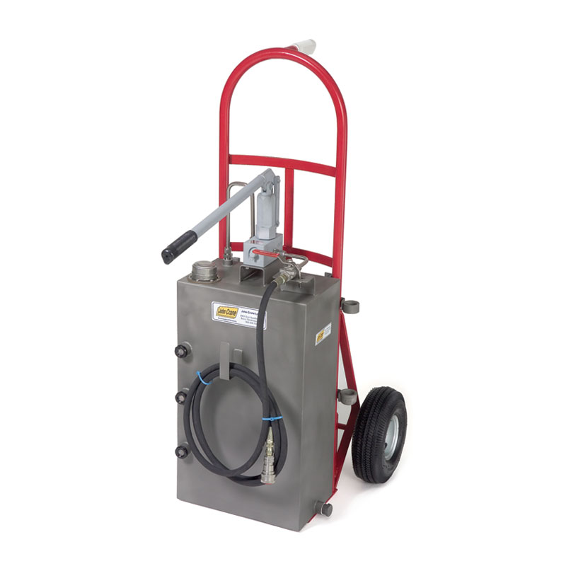
Pressurized barrier fluid reservoir circulation tank to ensure media will not leak into atmosphereDesigned to ASME Section VIII, Division 1, E2007, 2008a, Addenda standardsAvailable to build to (U) and (UM) stamps, registered with national boardFormation of fluid between seal faces provide a longer seal lifeModular design for various combinations of instruments and componentsAvailable with refill pumps, slide brackets, transmitters, switches and cooling coils
Tank Capacity: 2 Gallon, 3 Gallon, or 5 Gallon in 6" or 8" diameterOperating Pressure: 400 PSI @ 200°FTank Material: 304/304LCooling Capacity Coil: 1/2" x 0.065" wall seamless tube; 20" long 316/316LLevel Gauge: Weld Pad– Size 3Hydrostatic Test Pressure: 525 PSIAllowable Temp: -20° F to 200° FFill Port: 3/4" NPTSeal Connections: 1/2" NPTLevel Switch Connections: 3/4" NPT
Pressure Regulator specific to your applicationPressure Indicator 2 ½" Dial - Pressure specific to your applicationExplosion Proof Ultrasonic Level SwitchCode Stamp available either (U) or (UM)
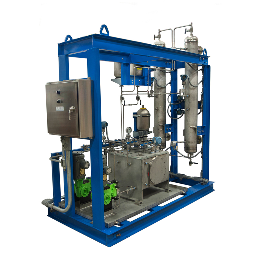
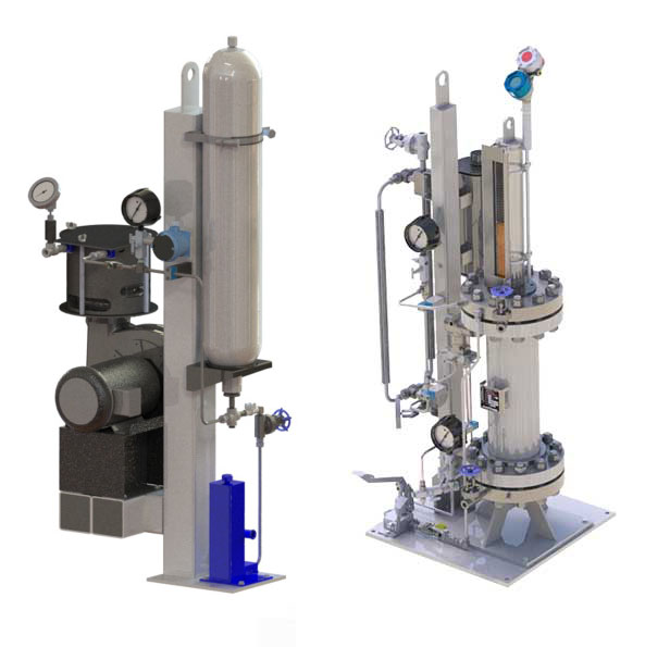
Carotek manufactures Seal Pot Pressure Vessel Tanks and Support systems in our Charlotte facility in Matthews, NC. The seal pots are built to ASME Section VIII and are available with ASME “U” and “UM” code stamps. As a premier industrial seal pot manufacturer, we offer standard and custom built ANSI / API mechanical seal support systems for industrial, chemical, and petrochemical applications. Seal pots provide a protective buffer between the product and the atmosphere, and isolate potential product leaks to the atmosphere. As a safety measure, seal pots perform a vital duty protecting the environment and personnel from the dangers of hazardous materials
Our Seal Pots our fully Made in America and meet all the requirements of ANSI and API specifications. Our modular designs are adaptable and can be combined with cooling coils, level switch/transmitters, pressure switch/transmitters, air coolers, and circulating pumps for a wide variety of applications. They are durable, flexible, and offer reliable performance for your demanding operations. Modular design supports various combinations of instruments and components such as built in refill pumps, transmitters, switches and cooling coils.
Seal Pot ASME Certificate of AuthorizationMade in AmericaQuick QuotesQuick DeliveryExpert application assistanceMillwright qualityTIG and MIG weldedBare Tanks with coil can be shipped next dayAvailable with ASME code stamp
Petro-Canada Lubricants’ PURITY FG Synthetic Barrier Fluids are advanced food grade barrier fluids formulated to deliver exceptional performance, by resisting degradation and deposit formation, and are also suitable for service in non-food grade industrial applications. These barrier fluids start clean and remain clean in the most demanding conditions.
PURITY FG Synthetic Barrier Fluid is a PAO based product formulated with specific additives to deliver exceptional protection against oxidation, corrosion, and wear. This NSF H1 registered product is designed to provide lubrication and cooling for mechanical seals to help maximize seal life.


 8613371530291