
bfp mechanical seal factory

Boiler feed pumps (BFPs) consist of feeding to a steam generator (e.g. boiler) a quantity of feedwater corresponding to the quantity of steam generated. Operating parameters (flow, head, temperature) of boiler feed water are calculated by a boiler designer.
Today, almost all BFPs are centrifugal pumps. The construction of BFPs in respect to shaft power, material, pump types and drive are governed by the developments which have taken place in power technology. The trend in fossil fuel power stations is continuously towards larger power block units.
Until 1950, the average discharge pressure of BFPs was in the 200 bar region. By 1955, it had risen to 400 bar. Mass flows were in the region of 350 tons per hour (t/h) in 1950 and have risen to 2,500 t/h (4,000 t/h) in conventional power plants. BFPs operate at temperatures of 160 C to 180 C, and in exceptional cases,
BFPs were constructed of unalloyed steels through the 1950s. Since then, 13% to 14% have pivoted to chrome steel (A743 Gr. CA6NM). This change in materials was made necessary by the introduction of new feedwater treatment processes. The development of high strength, corrosion-resistant chrome steels with emergency running characteristics paved the way for the current BFP with speeds of 5,000 to 6,000 rotations per minute (rpm). The flow rate of BFPs rose with the rise of power block outputs. Today’s full-load BFPs for traditional 750 megawatt (MW) power trains are constructed with four to five stages, with stage pressure up to 80 bar.
Electric motors (asynchronous motors) are used to drive the feed pumps. Speed adjustment of an electrically driven BFP is possible to achieve by several means, including using fluid coupling, variable frequency drive (VFD) into motor and gearboxes. If a plant has abundant steam available, a steam turbine can also be used for the driver unit. In several cases, condensing turbines running at 5,000 to 6,000 rpm are used. However, using condensate-type steam turbine increases the requirement of equipment into the train. It is essential to use a heat exchanger, condensate extraction pump or the like for effective use of the unit.
If a BFP is needed for high pressure and high rpm, a booster pump is required. In such a case, adequate net positive suction head available (NPSHa) is difficult to achieve and the booster pump fulfills the requirement. For reducing the net positive suction head required (NPSHr), it is possible to select the pumps making first stage (suction) as a double suction. NPSH is most significant at the suction stage only.
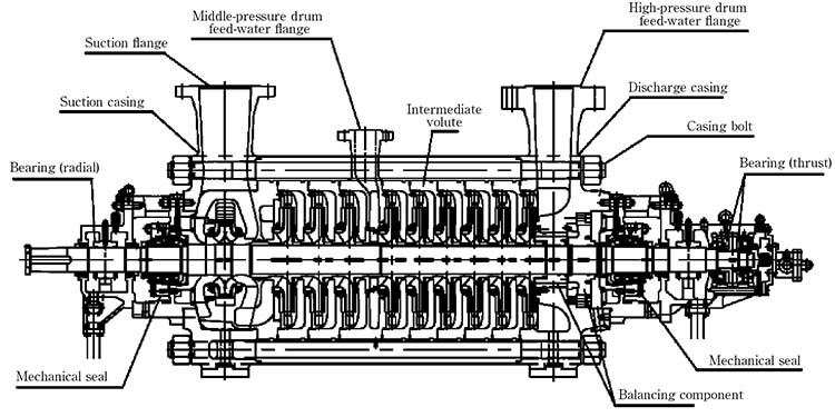
There are two types of construction mostly used for BFP application. One is a multistage barrel type pump, which is defined as a between bearings (BB) 5 type pump per American Petroleum Institute (API) 610. The other is a ring section multistage pump which is defined as a BB4 type pump. However, a ring section pump does not meet the criteria of
The pump casings of BFPs must be considered from two points of view: the wall thickness must be sustainable on one side to satisfy the pressure loading requirement and the other side needs to adapt itself to the temporary temperature variation which arises.
Barrel casings are usually made of ductile forged steel, and all surfaces in contact with the feed water are coated with the austenitic material by cladding process. To weld the pump casing into the pipeline, an intermediate piece made compatible for welding into the pipeline and the pump casing is welded onto the pump suction and discharge branches. The cover on barrel pumps are sealed by flattening a cellular metal spiral-wound gasket (sealing).
The casings of ring section pumps are constructed from cast or forged carbon steel—sometimes cast iron—depending on the application and requirement defined by the user. The sealing of each casing (stages) against one another is by metal-to-metal contact—the individual casings being clamped together axially by tie bolts between the suction and discharge pump casings. Metal-to-metal contact is one of the drawbacks of the ring section pump, as it restricts the use of the pumps in high temperature applications. Temperature shocks are absorbed by additional stresses on the tie bolts and sealing faces of the stage casings.
Water injection at a pressure situated between the suction and discharge pressures of the pump is a frequent service requirement. This is taken care of by tapping water from one of the pump stages—both in the case of barrel pumps and ring section pumps. These pressure zones are sealed off from one another by flexible spiral-wound gaskets and the flexibility and thermal shock behavior are suitably matched to one another.
BFPs are fitted with pump shafts, which have an appropriate distance between bearings and are combined with a large shaft diameter. The impellers are usually shrunk on the shaft, and consequently the static shaft sag is small. The shaft is insensitive to vibrations, and in normal running conditions, is smooth without any undesirable radial contact with the casing. The hub diameter is increased at the back of the impeller, and the impeller entry geometry is designed to keep the diameter as small as possible to reduce the axial forces which must be absorbed by the balancing device.
Additional disturbing forces can arise if pumps are operating in abnormal conditions. For example, if the pump starts to cavitate, it means the NPSH is not sufficient to run the pump smoothly. On the larger BFPs, the balancing of the axial thrust on the pump rotor is affected by means of a balancing device through which the pumped fluid flows, combined with an oil-lubricated thrust bearing. The hydraulic balancing device may comprise a balance disc with balance disc seat, or a balance piston or double piston with the associated throttling bushes. Pistons and double pistons can also be combined with a balance disc. It is important to note API 610 does not allow the use of a balancing disc, so a drum should be used. However, API 610 strictly pertains to petrochemical, oil and gas applications. In several cases, plants have prohibited the use of a balancing disc for the BFPs in typical power plants.
Radial forces arise from the weight of the rotor, mechanical out-of-balance and radial thrust. The balancing of the radial forces is affected by two oil-lubricated radial bearings and by throttling gaps by which fluid flows axially. These throttling gaps through which the fluid flows axially are located at the impeller neck, or in the case of multistage BFPs, in conventional power stations in the throttling bushes of the diffuser plates and on the balance piston. If the rotor is slightly eccentric, a centering restoring force will be generated in these gaps, and this force will be dependent on the pressure differential and on-the-gap geometry. This restoring action is usually called the Lomakin effect. It is reduced when the headwater in the gap flow is not in a purely liquid phase. The hydrostatic action of the throttling gaps in respect of mechanical stiffness can exceed the shaft stiffness. The system is tuned in a way that the critical speed of rotation always remains away from the operating speed. Hydraulic exciting forces, particularly under part load operation, can be absorbed in addition.
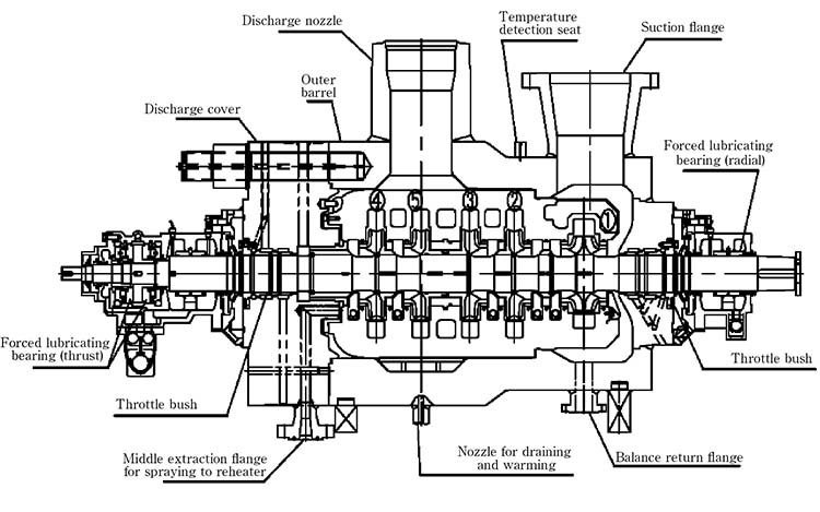
Soft-packed stuffing boxes, mechanical seals, floating seals and labyrinth seals can be used on BFPs for sealing purposes. The application limit of soft-packed stuffing boxes is governed by the existing possibilities for the removal of frictional heat. In the case of high duty, soft-packed stuffing boxes, there is usually a precooling of the leakage water and an ambient of the stuffing housing, shaft protection sleeve and gland. The packing material usually consists of braided Teflon twine. This shaft seal is used with success on full load feed pumps up to 150 MW power train capacity.
The small leakage of mechanical seals is emitted into the atmosphere in the vapor form at the exit. The frictional heat generated is less than in the case of soft-packed stuffing boxes. A closed-circuit cooling system is generally adopted—which is driven by a circulator device on the rotating seal ring when the pump is running and by thermosiphon action when the pump is stopped.
A floating seal can be used for high circumferential velocities and high sealing pressures. The floating seal consists of a series of short throttling rings which can be displaced radially. A stream of cold sealing water is injected into the seal to ensure that no hot water can leak out of the pump. This sealing water feed must be kept going while the pump is running under pressure. The control of the sealing condensate injection into a floating seal can be affected by differential pressure, regulation or by differential temperature regulation of the sealing condensate.
In case of high temperature application, more than 80 C, use a single acting mechanical seal with the cooler which is classified as Plan-23 as per API 682.
If BFP is switched on and off frequently, it is desirable to avoid thermal shock and warping of the casing after the pump has stopped to prevent premature internal wear at the sealing gap. In principle, the construction materials are selected in such a way that the BFP can be started up from any thermal condition. However, a physical contact between rotor and casing at locations with a close clearance cannot be avoided under certain circumstances of abnormal operation—e.g., when cavitation occurs, or during a semi-warm start, when the BFP is warped. The affected locations are the throttling gaps at the impeller inlet, the throttling bush in the diffuser and the balancing device. The matching of appropriate construction materials at these locations, consisting of corrosion-resistant chrome steels with special alloy additions ensures good emergency running conditions even at high circumferential velocities. Any high wear at close clearance gaps is always linked with a drop in efficiency.
A so-called minimum flow valve (e.g., an automatic leak-off valve, valves, and fittings), is arranged downstream of the outlet pipe if the BFP ensures that a minimum flow is always present and prevents any damage that might arise during low load operation, as a result of excessive overheating and evaporation of the contents of the pump, or as a result of cavitation at part load operation.
Essential fundamentals to emphasize for BFPs are proper pump warmup, standby warming and shaft (fixed bushing) seal drain temperature control. These characteristics have become more critical as central station plants are cycled and large feed pumps are operated with varying loads and in standby modes. Prewarming of the pump and maintaining warmup flow to an idle pump to assure dimensional thermal uniformity is essential to maintenance of internal clearances, pump efficiency and long life. This process is critical for multistage pumps to minimize thermal distortion. The distortion will cause the following potential failure modes: flashing, internal rubbing, increased wear ring clearances, pump seizure, worn seal bushing clearance and excessive leakage, loss of pump performance and efficiency, high pump vibration and worn bearings/bearing clearances.
reconditioning of mechanical seals of bfp pump and booster pump of make spem model hpt300 330 im 5s and model hzb253 640 and cep ksb make nlt 350 400x7 mechanical seal make lehe china and eagle burgmann at katpp jhalawar

One of PPC Mechanical Seals competitive advantages in the marketplace is our knowledge, experience, and facilities to repair and recondition all major brands of mixer seals. In addition, we can manufacture and design completely new seals for your units. PPC utilizes a dedicated mixer seal repair cell and is experienced in handling shaft diameters up to 9”+ inches. Our dedicated cell and experience mean that PPC has the fastest turn around in the industry for these types of seals.
The scope of our mechanical seal product range far exceeds any other seal manufacturer. From small elastomer bellows seals used in millions of domestic water pumps to double mechanical seals that ensure maximum sealing safety and large, highly customized dry-running gas seals for mission critical high speed turbo compressors, John Crane has the right product for any application.
Our world-class rotating equipment technologies, paired with an unmatched breadth of applied engineering expertise, meet virtually all international standards including API 682 and help plants reduce maintenance costs, slash down time and improve reliability. When it comes to keeping your rotational equipment running 24/7, John Crane’s comprehensive range of mechanical seals and systems has you covered.
A range of seals for mission-critical applications, designed to solve the application-specific challenges of each industry. From API 682 compliance for the oil and gas industries, using gas seal technology on our innovative pump gas seals to eliminate fugitive emissions, dealing with slurry in the mining and minerals processing industries, to the difficulties associated with maintenance on large pumps and rotating equipment — we have a solution.
Dry-running, non-contacting gas seals have been the industry standard since the early 1980s for turbomachinery. John Crane gas seals, separation seals and support, monitoring, control and conditioning systems — the heart of any reliable sealing solution — are constantly evolving to meet the needs of customers. The product portfolio is supported by unrivaled global service capability providing repair, retrofit, gas seal storage and reliability expertise, delivering total solutions throughout the product lifecycle.
In industries like chemical, pharmaceutical, pulp and paper, and food and beverage, safeguarding and compliance with industry standards, avoiding contamination and efficiency are always top priorities. Our range of vessel and agitator seals optimize equipment performance, maintain product purity and conform to industry regulations, no matter where you are.
Our range of mechanical seals, packing and bearing isolators combines advanced, thoroughly proven technologies with extensive industry expertise to create a range of products characterized by innovative design concepts and outstanding manufacturing quality. Tried, tested and effective solutions for virtually any application that deliver robust performance, reduced installation times and lower maintenance costs.
Create the optimum operating environment that will ensure outstanding seal performance and reliability. Our comprehensive range of engineered pressure reservoirs, gas seal control panels, heat exchangers and abrasive separators can be combined to produce the perfect seal support system for any application.
Designed to overcome rigorous challenges, our comprehensive suite of seal face technologies combat limited seal face lubrication that adversely affects reliability, cost and durability. Our engineers designed these face treatments to extend rotating equipment life through advanced micro machined patterns and features improving seal face lubrication that optimizes equipment performance. We deliver the right face technology for the right application.


 8613371530291