
mud agitator free sample

The USGI series of mud logging gas trap agitators - all are designed and manufactured in the USA by mud loggers. We have a complete mudlogging gas traps & repair parts. We"ve been in business over three decades because of our excellent customer service and vast catalog including mud logging gas trap agitators. Looking for something to fit inside that Mongoose shaker? Try our 5" mudlogging gas trap agitator, in both air and electric models. Our mud logging gas trap agitators are assembled and ready to ship the same day in most cases!

When you’re looking for the best selection in mud logging equipment & geologist supplies, US GeoSupply has just what you’re looking for. Whether it’s a mud logging gas trap, bubble jar, microscope, sieves, or any number of replacement parts for your mud logging gas trap, we have the geology and mud logging supplies to keep you at the top your game. Most orders ship same day! If you can"t find what you"re looking for, give us a call (970) 243-3044, chances are we can find it for you.
This invention relates to a system for the collection and extraction of gases entrained in a fluid, and more particularly, hydrocarbon gases in the return flow drilling mud material of an oil or gas exploration well.
There is a demand for apparatus to collect gases emitted from and extract gases entrained in fluid and slurry materials. For example, gases entrained in the return flow material discharged from an oil or gas exploration well. This return flow material is generally in the form of a mud stream and is usually referred to as drilling mud. Collection, extraction and analysis of drilling mud gases can be used to indicate the hydrocarbon content in the well return flow material which, in turn, provides the basis for an assessment of the formation and any indications that the well drilling has hit a producing zone. In an oil and gas well, generally the primary hydrocarbon gas of interest is methane gas. Thus, information relating to the methane gas content of the well return flow material is the information that is usually of most interest. Although, under certain drilling conditions, there is also interest in information relating to some of the other hydrocarbons that may be present in the well return flow material.
The current state of the art drilling mud gas sample collection, extraction systems have several problems that cause such systems to require high maintenance costs and attention. Current gas trap apparatus provides a canister with an electric motor mounted on top, which drives a centrifugal impeller housed centrally within the canister. The canister has a plate on the bottom with a small hole in the centre that acts as an inlet for the drilling mud. Another hole is provided in the side of the canister that forms an outlet for the drilling mud to be expelled from. This arrangement is designed both to pump mud through the gas trap sample canister and to agitate the mud contained within the sample canister sufficiently to permit entrained gases to be released. The gases are released from the return drilling fluid well mud stream as gas bubbles and are evacuated from the sample canister via a sample outlet, which couples to a sample tube.
Current gas traps are quite heavy, usually weighing 70 lbs. or more making the devices relatively heavy and, consequently, onerous to install, operate and maintain. Generally, the gas traps are attached to the shaker box and disposed inside of the shaker box, positioned at a particular depth in the drilling mud flowing through the shaker box. Typically, the apparatus for attaching the gas trap to the shaker box includes a bracket that permits up and down adjustment of the gas trap to allow the gas trap to be positioned at the correct depth in the drilling fluid. Positioning the gas trap at the prescribed or optimum depth in the drilling fluid is very important with the current design of gas traps. Any variation from the optimum depth causes the gas trap to change the amount of drilling mud it will pass in a given period of time as well as causing it to liberate more or less entrained gases from the drilling mud in that same given period of time. Furthermore, if the level of the drilling mud rises too high, drilling mud will be drawn into and through the sample tube by the sample pump toward the sample analyzer causing contamination of the equipment. Depending on the amount of drilling mud drawn into the sample tube, the sample handling, conditioning and analysis systems can all become contaminated with the drilling mud. At a minimum, drawing drilling mud into the sample tube will cause contamination that will require maintenance intervention and may necessitate replacement of the sample tube. In operation, most shaker boxes will experience a change in drilling mud level as the mass flow quantity of drilling mud changes or as the density and viscosity of the drilling mud changes. Drilling mud level changes in the shaker box can also occur as a result of the rig crew making adjustments to the shaker box itself.
U.S. Pat. No. 5,199,509 to Wright for a controlled gas trap system provides a gas trap forming a sample chamber having an inlet and outlet both submersed in the fluid to be sampled. Disposed within the gas trap is a rotating agitator and a vent to admit substantially gas-free air into the housing and a means to draw off the gas evolved from the mud. To provide for varying mud levels, the apparatus of Wright relies on the rotation of agitator to maintain a constant mud level within the sample chamber.
It is desirable to have a drilling mud gas sample collection, extraction system that is operable over a range of drilling mud levels within the sampled flow stream, for example, in a shaker box.
It is desirable to have a drilling mud gas sample collection, extraction system that operates consistently over a wide range of ambient temperatures, including freezing winter temperatures.
It is desirable to have a drilling mud gas sample collection, extraction system that operates consistently over a wide range of drilling mud viscosity.
It is desirable to have a drilling mud gas sample collection, extraction system that operates with little or no frequent operator maintenance or intervention.
The invention provides a gas trap assembly to recover sample gases from fluids having pneumatic motor driven agitator blade rotatably disposed within a gas sample collection canister. To enable operation of the pneumatic motor in winter conditions, the pneumatic motor compressed air supply has an air dryer to dry the air supply to a dew point below minus 40 degrees Celsius. The compressed air treatment system is housed in a heated environment to prevent the water extracted from the air from freezing up.
Within the gas trap, changing mud levels in the fluid flow in which the gas trap is disposed are controlled to a set or predetermined level using compressed air. To maintain the drilling fluid mud level at a consistent level within the gas trap, a two-chamber configuration is employed comprising a sample canister forming the first chamber and a bubbler enclosure or canister forming a second chamber. Compressed air is supplied in common to both chambers, consequently, the bubbler enclosure regulates the pressure within the sample canister to keep the mud level within it constant. The bubbler enclosure is sealed at the top and has an air exit port opening at the bottom at the level or point where the mud level in the sample canister is desired to be. The exit port opening at the bottom of the bubbler enclosure may be provided by cutting off the bubbler enclosure at the desired length. In operation of the gas trap, pressurized air is supplied to bubbler enclosure. The chamber formed by the bubbler enclosure is in common air communication with the sample chamber of sample canister through a passageway equalizing the pressure in the two chambers.
To operate the gas trap, the amount of air supplied to the bubbler enclosure is slightly greater than the amount of sample gas drawn from the chamber formed by the sample canister. Therefore, the bubbler enclosure will always be bubbling air out of the bottom as long as it is under the surface of the mud. The cavities formed by the bubbler enclosure and the sample canister are in communication with each other, consequently, the mud level maintained by the air pressure within the bubbler enclosure causes the mud level inside the sample canister to be at the same level. Variations in the drilling mud level exterior to the gas trap in the shaker box can rise a great deal without having any effect on the level of the drilling mud within the sample chamber of the gas trap. With this arrangement, the gas trap is prevented from “flooding”, that is, the condition where drilling mud is sucked up into the sample tube. In the event that main air pressure is lost, it would be possible for the gas sample extraction pump to suck the drilling mud into the sample tube following main air pressure loss.
In a preferred embodiment, the sample canister provides baffles projecting into the sample cavity formed by the sample canister. The baffles prevent or reduce mud fluids from entering into the sample tube.
In another of its aspects, the invention provides an apparatus to recover gases from a fluid that has a sample container adapted for submersion in a fluid. The sample container forms sample cavity therein and includes a fluid ingress port and a fluid egress port to provide a path for the flow of fluid through the sample cavity of the container. A sample extraction port is exterior to the sample container and in communication with the sample cavity. Agitator means is rotatably disposed within the sample cavity of the sample canister and a motor drives the agitator. A bubbler enclosure is attached to the sample container and has an exit port at a predetermined location in relation to the sample container. A supply port is adapted to receive a supply of pressurized gas into the bubbler enclosure and a passage extends between the bubbler enclosure and sample container to provide a path for communication of pressurized gas from the supply port to the sample cavity of the sample container.
In yet another of its aspects, the invention provides apparatus to recover gases from a fluid operable in freezing conditions including a sample container adapted for submersion in a fluid. The sample container forms a sample cavity therein and a fluid ingress port and a fluid egress port to provide a path for the flow of fluid through the sample cavity. A sample extraction port is exterior to the sample container and in communication with the sample cavity. An agitator is rotatably disposed within the sample cavity of the sample canister and motor means is provided to drive the agitator. A bubbler enclosure is attached to the sample container and has an exit port at a predetermined location in relation to the sample container. A supply port is adapted to receive a supply of pressurized gas and a passage extending between the sample container and the bubbler enclosure provides a path for communication of pressurized gas from the supply port to the sample cavity and the bubbler enclosure. The apparatus also includes a source of pressurized air and a heater to heat the pressurized air. A heat exchanger block is disposed on a frame supporting the sample canister and the bubbler enclosure to recover heat from the pressurized air.
In yet another of its aspects, the invention provides apparatus to indicate the relative viscosity of a fluid including an agitator adapted for rotatable placement in a viscose fluid. A pneumatic motor is provided to effect rotation of the agitator. A variable valve controls the supply of compressed air to the pneumatic motor means in response to a control signal produced by a controller. A sensor produces rotation signalling representative of the rotation of the agitator for the controller. The controller operates to maintain a substantially constant rate of rotation of said agitator by varying the control signal with relative changes in fluid viscosity.
Apparatus to recover gases from a fluid, or gas trap, constructed in accordance with the invention, generally depicted by reference numeral 34, is positioned within a fluid 36, for example, a well drilling mud return flow. The gas trap 34 is positioned in the fluid so as to place the lower portion of the gas trap below the surface level of the fluid mud level 38 to facilitate extraction of a gas sample by the gas trap from the fluid well return flow 36. The gas trap 34 is connected to analyzer equipment 26 by an insulated sheath 40, which houses air supply tubes running between the analyzer 26 and gas trap 34. A primary air supply tube 42 is used to supply air to drive the pneumatic motor 44 of the gas trap. A bubbler air supply tube 46 supplies air to a bubbler enclosure 48 of the gas trap 34. The sample gas recovered by the gas trap 34 from the fluid 36 is collected within the gas trap 34 for transport to the analyzer 26 via sample supply tube 50. Preferably, transducers monitor the operation of gas trap 34 provided in the gas trap to measure the gas trap temperature and the gas trap pneumatic motor 44 rpm. Signalling from these transducers is supplied to analyzer 26 by trap signalling line 52.
The gas recovered from the fluid 36 is collected in a sample canister 60, which extends down from frame 54 to form an interior sample collection cavity 62. The sample collection cavity 62 is in communication with the cavity 49 formed by the bubbler enclosure 48 via passage 64 extending therebetween. To use the gas trap, the lower portion of the gas trap is submersed within a fluid 36. A supply of compressed air is provided to the gas trap via the bubbler air supply tube 46. The compressed air is contained within the bubbler enclosure 48 that becomes pressurized with the compressed air supplied to cavity 49. When cavity 49 fills with compressed air, bubbles 66 escape from the lower extremity of bubbler enclosure 48 into the fluid 36 that the gas trap has been positioned in, for example, well drilling mud return flow. The compressed air causing pressurization of the cavity 49 of the bubbler enclosure 48 is applied also to the sample collection cavity 62 of the sample canister 60 as the cavities 49 and 62 are in communication via passage 64. The common pressurization of cavities 49 and 62 causes the fluid level within cavity 62 of the sample tube to be at the same level as the fluid within cavity 49 of the bubbler enclosure 48.
The bubbles 66 will not exit the bubbler enclosure 48 until the cavity mud level 68 reaches a level where the compressed air supply can exit the cavity 49 of the bubbler enclosure 48. The preferred manner of controlling the bubbler cavity compressed air exit level, and therefore the fluid level in the bubbler cavity 49, is simply to cut the bubbler enclosure 48 at the desired length. This manner of construction leaves a relatively large exit opening from bubbler enclosure 48 which avoids fouling and plugging of the exit opening by the mud 36. The lower extremity of bubbler enclosure 48 is positioned or disposed relation to the sample canister 60 to select or locate the desired fluid mud level within sample canister 60.
The quantity of compressed air supplied to bubbler enclosure 48 via the bubbler air supply tube 46 is set, for example at the analyzer 26, to supply a quantity of air that is slightly more than the gas sample which is extracted from sample cavity 62. In this manner, the excess air supplied to cavities 49 and 62 will be sufficient to cause bubbles 66 to exit bubbler enclosure 48 at the exit opening, for example, at the foot thereof. Consequently, irrespective of the mud level 38 exterior to the gas trap, the cavity mud level 68 will always be located at the foot of the bubbler enclosure 48. Because bubbler cavity 49 is in communication with sample cavity 62 via passage 64, the average mud level within cavity 62 will be at the same level as the cavity mud level 68.
In the interior of sample canister 60 is an agitator 70 that is driven in rotation by pneumatic motor 44. In operation, agitator 70 will rotate at an angular velocity of approximately 1700 rpm. The rotation of agitator 70 within the fluid 72, for example well drilling mud, contained within the sample canister 60 will cause the well drilling mud to be agitated or whipped and to develop an inclined conical surface 74.
Sample canister 60 has an egress port 76 formed in the lower portion thereof at a position such that the upper portion of conical surface 74 will extend toward egress port 76. While agitator 70 is rotating, a continuing portion of the well drilling mud agitated by agitator 70 will reach upward toward egress port 76 where it will overflow into egress port 76 to exit sample canister 60 for return to the well drilling mud main fluid flow 36. To prevent exchange of gases between the interior and exterior of sample canister 60 through egress port 76, a baffle 78 is provided. Baffle 78 forms an opening 79 that is below both the surface 38 of the well drilling mud fluid 36 and below the mud level 68 of the cavity in the bubbler enclosure 48. The opening 79 is below the mud level 68 in the bubbler enclosure 48 to ensure that the excess compressed bubbler air exits only out of the bubbler cavity via bubbles 66 and does not flow through the sample cavity 62. Replenishment fluid, for example drilling mud, enters the chamber or sample cavity 62 of the sample canister 60 in the direction of arrow 80 through ingress port 82. Naturally, ingress port 82 is below the fluid level 68 set by the bubbler enclosure 48. Agitation of the sampled well drilling mud fluid 72 within sample canister 60 by agitator 70 assists to release gases into sample cavity 62 that are entrained in the well drilling mud mixture.
Collected sample gases are evacuated or extracted from sample cavity 62 via port 84. The gas sample extraction port 84 is in communication with sample outlet coupling 86 to permit coupling of a sample transport tubing to the gas trap to permit the extracted gas sample to be transported to analysis equipment. To prevent contamination of the sample gas pathways, baffles 63 extend from the sample canister wall and agitator shaft 91 and act to block splashing mud from reaching and fouling the sample port 84.
Pneumatic motor 44 is coupled to agitator 70 via a coupling 98. A seal 100 is provided on the cavity side of frame 54 to keep debris and moisture from escaping the sample cavity 62 and fouling the bearings 101 disposed between agitator shaft 91 and frame 54. A rotational sensor 102 is provided to produce signalling representative of the revolutions per minute (rpm) of agitator shaft 91. The RPM signalling is output on line 104 for use by monitoring equipment, for example, by analyzer 26. The temperature of the sample gas leaving the gas trap is measured by a gas trap sample temperature sensor 106, which provides sample temperature signalling on line 108 for use by monitoring equipment, for example, by analyzer 26.
FIG. 6 is an exploded schematic view of the gas trap apparatus of FIG. 1. The sample canister 60 has a removable bottom 110, which forms the fluid ingress port 82 for the sample canister. A coupling 98 couples motor 44 to the agitator shaft 91. An exhaust muffler 112 is provided for exhaust air discharged from pneumatic motor 44. A mounting bracket 114 is attachable to a main frame 54 and includes arm 116 which couples to a mounting bracket on the shaker box to which the gas trap will be mounted. The trap signalling line 52 contains the sensor signalling lines 104 and 108 therein.
The compressed air supplied to the gas trap 34 from the analyser 26 in the main air supply hose 42 can be heated but is not cooled. Consequently, the temperature of the gas trap 34 is controlled for low outside temperatures. The temperature sensor 106 in the gas trap heat exchanger block 88 provides a temperature feedback. The heat exchanger block 88 in turn heats the humid sample gas recovered from the drilling mud fluid to avoid sample freezing or condensation in the gas trap during winter conditions. The co-located tubes 42, 46 and 50 within sheath 40 provide a heat exchange surface along their length, principally between the main air supply hose 42 and the sample supply tube 50 to provide heating to the sample gas when it leaves the gas trap 34. The heated air supplied to the gas trap 34 exits the heat exchanger block 88 where it is supplied to power and warm the air-motor 44, promoting prolonged motor life expectancy in winter operation.
In operation, the gas trap 34 may become fouled by mud clogging the sample tube gas sample extraction port 84 or by water forming in the gas sample tube 50. These conditions will interfere with the operation of the analysis system, for example, cause a reduction in the sample gas flow rate. To effect self cleaning, gas sample variable control valve 136 is closed and a reverse flow of compressed air to the gas sample supply tube 50 is effected by opening reversing valve 138 to supply compressed air to the sample supply tube 50 via coupling 50′. In this manner, analyzer 26 operates to effect a cleaning process of the gas trap.
This allows for constant speed agitation of the mud in the sample canister of the gas trap and results in gas readings that are consistent even with variable mud viscosity. Controller initiated variation in the rate of compressed air supply to maintain constant speed of the air motor 44 provides a relative indication of mud viscosity and can be monitored by controller and output on an output means such as display 125. Display 125 is preferably remote from analyser 26, as for example, at a remote computer system.
Restrictor 130 sets the constant rate of supply of the bubbler air supplied to the gas trap 26. The sample received from the gas trap arrives at the analyzer 26 at coupling 50′ which couples to the gas sample supply tube 50. The flow rate of the gas sample is monitored by flow meter 132. The sample is drawn into analyzer 26 by means of a pump 134 and the rate of flow of the gas sample into the analyzer 26 is controlled by the sample variable flow control valve 136 to a constant rate, for example, 500 ml. per minute. Restrictor 128 sets the bubbler air supply rate flow to the gas trap 34 and the bubbler air supply rate is greater than the sample gas supply rate. In this manner, analyzer 26 sets the bubbler gas supply rate corresponding to the gas sample supply rate to ensure that excess bubbler air is supplied to the gas trap 34 over the sample gas flow rate which is supplied to the analyser. The excess bubbler air is provided to ensure that the bubbler enclosure 48 is bubbling excess air when the gas trap is in operation. In this way, flooding of the trap is prevented irrespective of an increase in the mud level that the trap is positioned in.

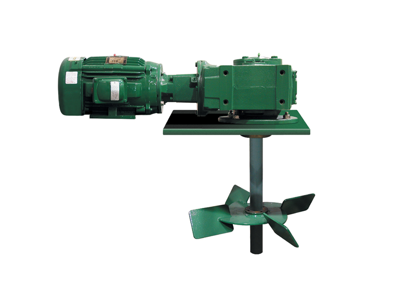
Derrick mud agitators include an explosion-proof, “C” faced motor, reduction gearbox (helical-bevel gears for horizontal agitators or all helical gears for vertical units), impeller, and shaft with assembly bushings. Motors range from 5 to 30 HP and may be supplied in several power configurations.
Attaching the motor directly to the gearbox protects correct alignment that can increase bearing life and provides 95 percent efficiency in power transfer to the impeller. Using this superior design surpasses standard worm drive gear assemblies by 30 percent, allowing Derrick agitators to do the same work at far less horsepower. By unitizing the motor and gearbox, weight and space requirements are reduced. Horsepower, mechanical configuration, impeller diameter, and shaft length are customized to tank dimensions and maximum mud weights. Available horsepower ratings* are: 5, 7.5, 10, 15, 20, 25, and 30.
mud tanks are important rig components that are used for storing mud for oil and gas drilling operation. We will discuss about mud tanks miscellaneous components .
Used to shear/mix mud in the mud tank it is usually installed near toCorner of mixing tank. It enhance agitation of mud, Where agitation byagitator is limited, as agitator is installed in the middle of tank.It can be used to transfer mud between the mud tanks.

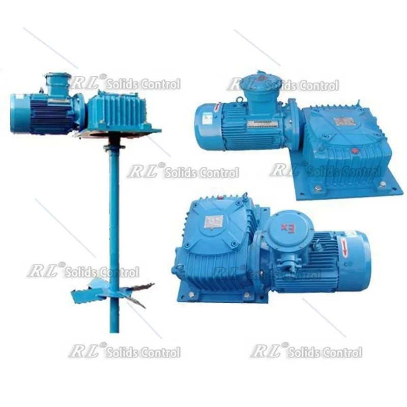
When you need to gain rapid access to the essential wholesale mud agitator 15kw supplies that your business relies on, head to Alibaba.com where you"ll find thousands of Chinese wholesalers ready to provide the equipment, materials, consumables and products that you need to run your business. From mud agitator 15kw supplies that cover all technical specifications through to associated products and office consumables, you can buy everything that your business needs in one place at Alibaba.com.
Simply use the search filters and categories to swiftly find details of mud agitator 15kw prices, specifications, order volumes, lead times, discounting arrangements and more. See what other customers thought of individual wholesalers with the customer review feature and see images of operations, markets served and more. You can even chat instantly with sales and support or send an email at any time of day.
Ready to make your mud agitator 15kw order? Just do so in a few clicks in your private account area and you"ll receive regular updates on your shipment so that you know exactly where it"s at in the world until it arrives at your business! It"s swift, convenient and cost-effective to shop at Alibaba.com where you"ll find everything that your business needs to operate smoothly and without delay.


 8613371530291