
brandt mud agitator parts supplier
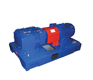
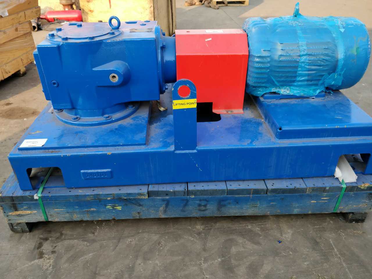
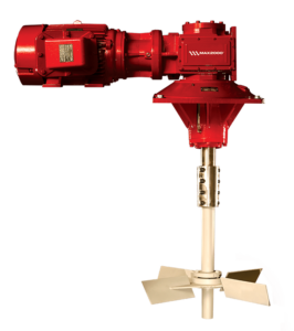
The skid mounted MA-RG agitator is compact, and its low profile reduces headroom requirements and provides more layout space on top of the tanks. The gearbox is a triple-reduction helical-bevel gear drive system that reduces the rotational speed of the motor to drive the impeller(s). Up to 95% mechanical efficiency helps reduce horsepower requirements.
Impellers are available with flat blades (radial flow), contour blades (axial flow), and canted blades (radial/axial flow). The impellers are sized according to tank volume and expected duty. Active mud system compartments—such as solids removal sections, mud mixing sections, and slug pits, which need a higher shear force to produce immediate mixing—are another consideration in impeller sizing.

BRANDT D-SANDER TYPE SR-2, SR-3BRANDTEA1282.203.BRANDT.0016GASKET,6″,VICTAULIC P584-10AG FOR STYLE 75,77,78(BRANDT PN 10AG) (CROSS REF 1282.203.0220)10
The Brandt Group of Companies is a dynamic and diverse group of companies headquartered in Regina, Saskatchewan. Brandt employs over 6000 people and services markets in Canada, the United States, Europe, Australia, New Zealand and Asia.

DrillingParts.com is in no way affiliated with the companies referenced in this website. References and/or mention of company names or the accompanying computer code are for ID purposes only and are not Trade Marks or Trade Names used by or affiliated with DrillingParts.com. Although under affiliate program agreements, DrillingParts.com may earn on qualifying purchases completed through third party associates such as Amazon, eBay and our marketplace vendors.
DrillingParts.com is in no way affiliated with the companies referenced in this website. References and/or mention of company names or the accompanying computer code are for ID purposes only and are not Trade Marks or Trade Names used by or affiliated with DrillingParts.com. Although under affiliate program agreements, DrillingParts.com may earn on qualifying purchases completed through third party associates such as Amazon, eBay and our marketplace vendors.

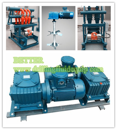
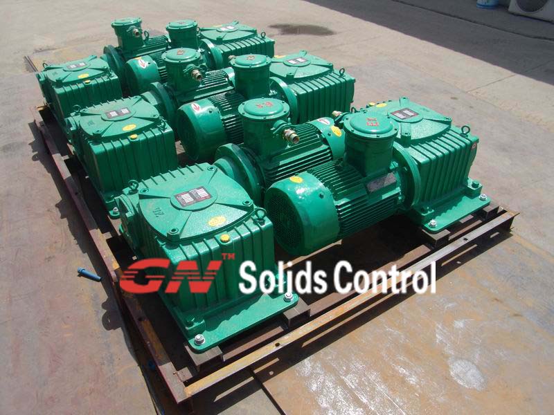
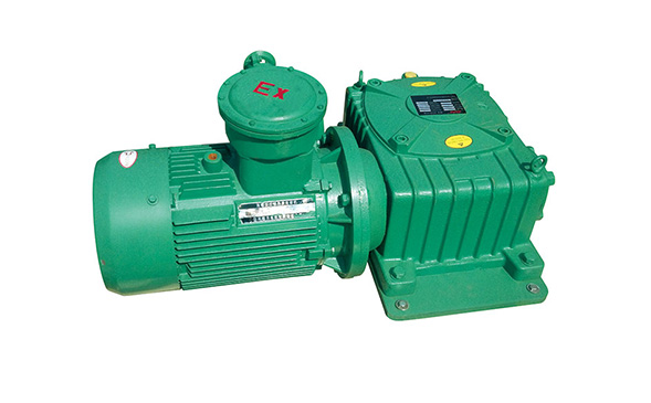
JBQ series mud Agitator, Less than 5.5 kW drilling mud Agitator adopts the blender cycloid speed reducer, and it is applied to the drug liquids mixing tank. This mud agitator has the advantage of compact structure so it occupies small area. More than 7.5 kW Mud Agitator uses the turbo and worm gear speed reducer, with the large torque transmission、 the revolution is steady、it works reliablely and has great merit. Common model of mud agitator is JBQ5.5kW 、JBQ7.5kW 、JBQ11kW and JBQ15kW.The drilling mud agitator is an important components for GN Solids Control drilling fluids processing system.
GN Solids Control as a professional manufacturer for soilds control equipments, we have designed lots of high-quality products, and JBQ series Agitator is one of them. To keep both the mud uniformity and the suspension of solids, the mud agitator is used to agitate the mud consecutively and reliably.This agitator agitates the mud to make cuttings, silt and sand pass the solids control system without being precipitated onto the tank bottom. Due to the simplex turbine decelerator, this product is featured by compact construction, light weight, balanced transmission, low noise, high efficiency of transmission and strong agitating power. Therefore, it is a reliable product in the solids control system.
China manufacturer GN Solids Control offer the world with drilling mud agitator equipments.We are an exporter of drilling fluid mud agitator for Indian, Russian,middle east.etc..Our factory and company are Quality Management System ISO 9001-2000 certified.GN Solids Control operate international oil gas drilling mud separation system sales,service,manufacturing,distribution serivce.Buy drilling fluid mud agitatorfrom China manufacturer.Your best mud agitator for drilling mud circulation system.

BETTER produce high-efficiency mud agitator, equivalent to BRANDT™ Agitators MA series, its rugged design, simplicity and dependability have made it the preferred choice of a majority of operators and contractors.

Brightway mainly supplies four serises kind of shale shaker screens applied to shale shaker, desilter, desander, and mud cleaner. Composite material shaker screen ,Steel Frame Shaker Screen ,Pyramid Shale Shaker Screen,Hook Strip Flat Shaker Screen.
Mud Tank Suction Valves & Dump Valves is the mud control equipment installed in the inside of mud tanks or water tanks. It is used to import mud or liquid phase and prevent different nature of mud or liquid in both side of mud tank to mix with each other.
Brighway Solids Control is one of the Mud Agitator Suppliers in the world. Mud Agitator Power includes 5.5kw Mud Agitator, 7.5 kw Mud Agitator, 11kw Mud Agitator, 15kw Mud Agitator etc.
As we know, there are many good Mud Agitator Suppliers in the oilfield, such as Derrick, Brandt NOV, Swaco etc. Brightway company is also good Mud Agitator Supplier from China. Brightway Mud Agitators are manufacture as the international standard, so can be used oilfield mud tanks or drilling mud system.
Brighway BWJBQ series mud agitators is widely used in the 200bbl 500bbl 600bbl mud tanks of drilling rig mud system. As the Mud Agitator Supplier, At present, Brightway BWJBQ series mud agitators had been exported to 40+ countries. such as: UAE, Saudi Arabia, Iraq, Iran, Kazakhstan, Pakistan,Poland, Turkey, Australia, New Zealand, India, Indonesia, South Korea, Thailand, Malaysia, Singapore, Taiwan, Egypt, Nigeria, Brazil, Argentina and Venezuela etc.
Compare other Mud Agitator Suppliers, Brightway can supply the customized Mud Agitators according to the customers request. for exmple, the Mud Agitators impellers can be design the single impeller or duble impellers, also the length of Mud Agitatormud agitators shaft can be design according to the deepth of the mud tanks. More useful information about mud agitators :Four Mud Agitator Impeller Type
Drilling mud agitator is a special agitator for oil drilling solids control. There are different specifications and models. It cannot be simply used in chemical, petroleum refining, food and other industries. How to choose a drilling mud agitator, here are 4 aspects to pay attention to. Rotating speed of drilling...
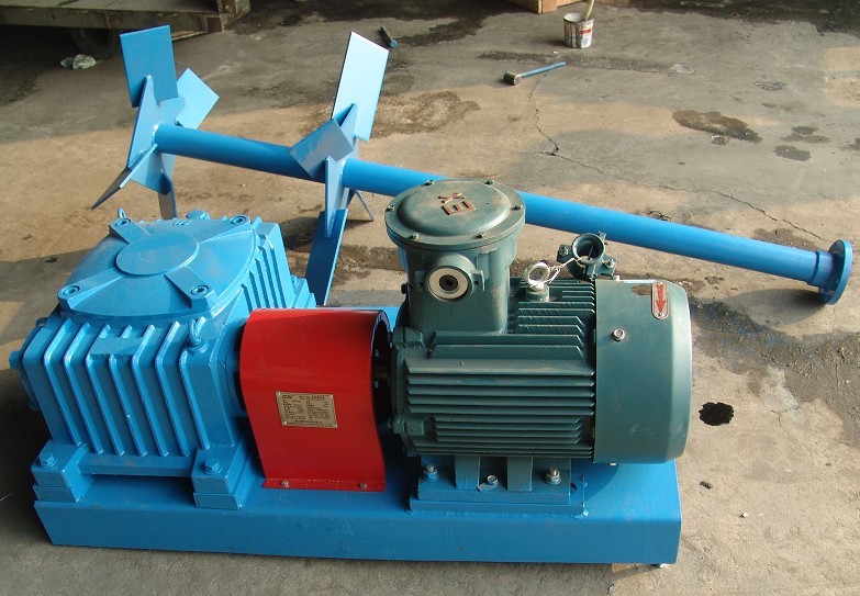
The Offshore 15 KW Mud Mixers Specifications: 1. The mud mixer consists of an electric motor and a reducer, a blade, and an extension shaft, connected with each other via soft connection coupling, on the common horizontal frame. 2. Type of mud mixer: mechanical, with a blade 3. Electric motor: 15 kW, 1460 d/d, 380
Brightway is the mud agitator manufacturer in China and has the competitive mud agitator price for our customer. Mud Agitator Price is composed of two parts, one is the Mud Agitator Power you will use, and the other is the material of the impeller and length of the impeller. So if you want the details
Brighway Solids Control is one of the Mud Agitator Suppliers in the world. Mud Agitator Power includes 5.5kw Mud Agitator, 7.5 kw Mud Agitator, 11kw Mud Agitator, 15kw Mud Agitator etc. As we know, there are many good Mud Agitator Suppliers in the oilfield, such as Derrick, Brandt NOV, Swaco etc. Brightway company is also...
In Oil Gas Drilling Rig, How many mud agitators are needed for 500 bbl Mud Tank? We know that: 500 bbl Mud Tank: 500 bbl is approximately equal to 80m³ (13x3x2.45 m). Mud Agitators: 10hp=7.5kw 15hp=11kw 20hp=15kw, For 500 bbl Mud Tank, How should we choose the Mud Agitator? In general If we choose the 15hp 11kw ...
Mud Agitator Impeller Types: pulp, turbo, disc turbine and propulsion. As the mud agitator manufacturer, Brightway can supply Four Types Impeller Mud Agitator. Mud agitator mainly makes the solid particles suspended in the drilling fluid. Drilling cuttings are the main component of the harmful solid phase. To get rid of...
Lightweight, but sturdy construction with the highest torque rating in the industry. Example: 15 hp KOE Agitator weighs 246.4 kg compared to industry average of 831.8 kg)
Brandt agitators serve the drilling industry with quality, time- Vertically mounted agitators mount the motor in line with the proven mechanical agitation. The Brandt horizontally mounted gear reducer and output shaft. The explosion-proof, C-face MA™-series agitator has been the industry standard for many motor bolts on and couples to the double reduction helical years. Its rugged design, simplicity and dependability have gearbox. The entire assembly bolts to a fabricated steel base made it the preferred choice of a majority of operators and plate, which is mounted on the mud pit. contractors. The low profile of Brandt horizontal agitators reduce Vertically mounted agitators are lighter than right- headroom requirements. They come in two styles. angle-drive horizontal units, but produce the same mixing Brandt’s original MA™ series with 30:1 single results. In some instances horsepower requirements are reduction worm-gear drive that uses a sliding action worm and reduced due to the 95% efficiency of the helical gearing. gear. Available in 3, 5, 7.5, 10,15, 20, 25, and 30 HP. Impellers Brandt’s new MA-RG (Right Angle Gear) double Brandt agitators are available with three types of reduction,helical gear designed primarily for applications impellers and are sized according to tank volume and expected requiring more than 15 horsepower can be used for large duty. Active mud system compartments (such as solids displacement applications. Up to 95% mechanical efficiency removal sections, mud mixing sections and slug pits) need a helps reduce horsepower requirements compared to conven- higher shear blade to produce more immediate mixing. tional designs. Therefore Brandt recommends either a flat blade or canted The 1:1 ratio of height-to-width of both designs blade, depending on tank depth. Bulk storage compartments results in a low center of gravity, providing stability and safety. need a low-shear blade that maintains suspension in a gentler Brandt VMA™series (Vertical Mechanical Agitator) is manner. ideal for installations with limited footprint availability. These For active mud system compartments less than 5 feet double-reduction, inline, helical gear agitators provide smooth, in height, a flat blade impeller can be used to induce radial flow vibration-free operation and efficient mixing, just like right-angle patterns in the mud. Flat bladed impellers should be placed Brandt agitators. approximately six inches above the tank or two inches above the bottom shaft stabilizer, if one is used. Brandt Agitators™
When compartment height is greater than 5 feet, either a 60- Regardless of what style agitator or impeller is used, properdegree canted impeller, or a high volume contour blade is used sizing is critical. Impeller sizes are determined by calculatingto promote axial as well as radial flow. Canted impellers should the TOR (Turn Over Rate) for each agitated compartment. TOR isbe placed on the shaft so that the distance between the bottom of the time required, in seconds, to completely move the fluid in athe tank and the lower edge of the impeller blades is equal to ¾ mud tank and can be calculated by knowing the tank volume andthe diameter of the impeller. For tanks deeper than 12 feet, two impeller displacement.or more impeller blades may be used in combination. Vt TOR = × 60 For bulk storage tanks, high-efficiency, contour Dimpellers are best. This variable pitch impeller reduces Vt = Tank volume gallonshorsepower requirements and induces less shear to the mud. D = Impeller displacement in gpm (as calculated Shafts by Brandt engineering staff and displayed in chart above) Manufactured of solid mild steel, the agitator shaft is For tanks sized to metric specificationscoupled to the gear reduction assembly with a rigid coupling. All Vt = Tank volume litersshafts are keyed at the bottom for adjustment of impeller height. D = Impeller displacement in lpm (as calculatedA bottom end stabilizer is supplied when tank depths exceed 6 by Brandt engineering staff and displayed in chart above)feet. The stabilizer reduces side loading and protects the agitator For 60-degree canted blade applications TOR shouldwhen auxiliary equipment is carried inside the mud tanks during be between 40 and 90 seconds. As the TOR approaches 40rig moves. seconds, the chance for air entrainment increases. At TOR greater than 90 seconds, proper suspension may be jeopar- T Y P I C A L T U R N O V E R R A T E P E R C O M P A RT M E N T dized and solids will begin to settle. SHAKER INTERMEDIATE SUCTION RESERVE PILL For contour blade applications, TOR must be signifi- Canted 50- 75 50- 75 65- 85 50- 80 40- 65 Impeller cantly faster to achieve the same results, but because of the Contour 25- 38 25- 38 32- 42 25- 40 20- 32 100% axial flow, air entrainment is not a problem. Blade Brandt Agitators™
Model HP Length Height Width Min. Impeller Shaft Shaft Agitator Length Height Width Min. Shaft Shaft Agitator (in) (in) (in) Dia. (in) Diameter Wt. Less Shaft (mm) (mm) (mm) Impeller Diameter Wt. Less Shaft Canted - Contour (in) (lbs/ft) & Impeller Dia. (mm) (kg/m) & Impeller Wt. (lbs) (mm) Wt. (kg)MA3 3 35 1/4 15 11/16 19 9/16 24 28 1 3/4 8 1/4 406 895 398 497 610 44 12 184MA5 5 40 1/4 16 3/4 21 9/16 28 34 2 3/8 15 580 1022 425 548 711 60 22 263MA7.5 7.5 52 1/8 24 1/4 27 5/8 32 38 2 3/8 15 1200 1324 616 702 813 60 22 544MA10 10 52 1/8 24 1/4 27 5/8 32 42 3 24 1224 1324 616 702 813 76 36 555MA15 15 52 1/8 24 1/4 27 5/8 36 48 3 24 1320 1324 616 702 914 76 36 599MA20 20 61 1/4 27 1/8 34 1/4 40 52 3 1/4 28 1898 1556 689 870 1016 83 42 861MA25 25 68 5/8 30 7/8 39 1/2 40 60 3 1/2 32 3/4 3130 1743 784 1003 1016 89 49 1420MA30 30 68 5/8 30 7/8 39 1/2 40 64 3 1/2 32 3/4 3180 1743 784 1003 1016 89 49 1442
Brandt agitators provide more thorough mixing of pits and Contact Brandt for proper agitator sizing. eliminate the problems associated with mud guns, such as Specifications are subject to change without prior notice particle degradation and gun nozzle washout. Brandt agitators can be sized to fit any mud system or type of duty. From Flowline To Disposal, Brandt has the solution to your separation and waste management Western Hemisphere Eastern Hemisphere Phone: (713) 856-4100 Phone: 44-1224-343600 problems. We are one of the Varco Companies; technology Fax: (713) 856-4133 Fax: 44-1224-343700 leaders to the drilling industry. www.varco.com brandt-rigtech-uk@varco.com This is not a complete list of all locations. Call for the location nearest you.
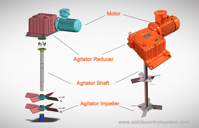
M14030MA-RG SeriesInstallation, Operation, and Maintenance ManualHelical-Bevel Gear Mud AgitatorP.O. Box 2327Conroe, TX 77305-23272800 N. FrazierConroe, TX 77303936-756-4800 phone936-523-2788 faxbrandt@nov.com e-mail Copyright 2007 National Oilwell Varco International, Inc. NOV Brandt is a registered trademark of National Oilwell Varco International, Inc.All other product, brand, or trade names used in this publication are the trademarks or registered trademarks of their respective owners.All rights reserved. This publication is the property of, and contains information proprietary to National Oilwell Varco International, Inc. No part of this publication may be reproduced or copied in any form, or by any means, including electronic, mechanical, photocopying, recording or otherwise, without the prior written permission of National Oilwell Varco International, Inc.Information in this document is subject to change without notice.WarrantyNOV Brandt warrants that, for a period of one year from the date of delivery equipment of NOV Brandt manufacture, the Equipment shall be free of defects in materials and workmanship under normal use and service, and provided the Equipment is used and maintained in accordance with instructions supplied by NOV Brandt. This is NOV Brandt"s sole and exclusive warranty. If a defect in the Equipment appears within one year from the date of shipment, and Purchaser has given written notice of such defect within thirty days from the discovery thereof, NOV Brandt will repair or replace the part, at its option, by shipping a similar part FOB shipping point or, at its option, refund an equitable portion of the purchase price. NOV Brandt may require the return, to a designated NOV Brandt location, of the defective part, transportation prepaid to establish Purchaser"s claim. No allowance will be made for repairs undertaken without NOV Brandt"s written consent or approval. This warranty applies only to equipment manufactured by NOV Brandt. Warranties on equipment manufactured by others, if any, are assigned to Purchaser by NOV Brandt (without recourse) at time of delivery. Any description of Equipment, drawings, specifications, and any samples, models, bulletins, or similar material, used in connection with this sale are for the sole purpose of identifying the Equipment and are not to be construed as an express warranty that the Equipment will conform to such description. Any field advisory or installation support is advisory only. The foregoing warranties are in lieu of all other warranties, whether oral, written, express, implied or statutory. Implied warranties or merchantability and fitness for a particular purpose will not apply. NOV Brandt"s warranty obligations and purchaser"s remedies thereunder are solely and exclusively as stated herein. Purchaser"s sole and exclusive remedy, whether based upon warranty, contract or tort, including negligence, will be to proceed under this warranty. All liability of NOV Brandt shall terminate one year from the date of delivery of the Equipment. 6Maintenance and Repair 7 5Parts and DrawingsTroubleshooting 8Worldwide Locations 3 2InstallationProduct InformationGeneral Information 1 4OperationMA-RG Series iTable of Contentsii NOV BrandtM14030 R3 Table of ContentsGeneral InformationIntended audience . . . . . . . . . . . . . . . . . . . . . . . . . . . . . . . . . . . 1-1Conventions. . . . . . . . . . . . . . . . . . . . . . . . . . . . . . . . . . . . . . . . 1-1Notes, cautions, and warnings . . . . . . . . . . . . . . . . . . . . . . . . . . . . . . . . . . . 1-1Notes . . . . . . . . . . . . . . . . . . . . . . . . . . . . . . . . . . . . . . . . . . . . . . . . . . . . . . . . 1-1Cautions . . . . . . . . . . . . . . . . . . . . . . . . . . . . . . . . . . . . . . . . . . . . . . . . . . . . . . 1-1Warnings . . . . . . . . . . . . . . . . . . . . . . . . . . . . . . . . . . . . . . . . . . . . . . . . . . . . . 1-1Illustrations . . . . . . . . . . . . . . . . . . . . . . . . . . . . . . . . . . . . . . . . . . . . . . . . . . 1-2Safety requirements . . . . . . . . . . . . . . . . . . . . . . . . . . . . . . . . . 1-2Personnel training . . . . . . . . . . . . . . . . . . . . . . . . . . . . . . . . . . . . . . . . . . . . . 1-2Recommended tools . . . . . . . . . . . . . . . . . . . . . . . . . . . . . . . . . . . . . . . . . . . 1-2General system safety practices . . . . . . . . . . . . . . . . . . . . . . . . . . . . . . . . . . 1-3Replacing components . . . . . . . . . . . . . . . . . . . . . . . . . . . . . . . . . . . . . . . . . 1-3Maintenance . . . . . . . . . . . . . . . . . . . . . . . . . . . . . . . . . . . . . . . . . . . . . . . . . 1-3Proper use of equipment . . . . . . . . . . . . . . . . . . . . . . . . . . . . . . . . . . . . . . . . 1-3Product InformationIntroduction . . . . . . . . . . . . . . . . . . . . . . . . . . . . . . . . . . . . . . . . 2-1Unit description . . . . . . . . . . . . . . . . . . . . . . . . . . . . . . . . . . . . . 2-1General description. . . . . . . . . . . . . . . . . . . . . . . . . . . . . . . . . . . . . . . . . . . . 2-1Motor . . . . . . . . . . . . . . . . . . . . . . . . . . . . . . . . . . . . . . . . . . . . . . . . . . . . . . 2-2Gearbox. . . . . . . . . . . . . . . . . . . . . . . . . . . . . . . . . . . . . . . . . . . . . . . . . . . . . 2-2Mounting base. . . . . . . . . . . . . . . . . . . . . . . . . . . . . . . . . . . . . . . . . . . . . . . . 2-2MA-RG Series iiiM14030 R3 Table of ContentsImpeller . . . . . . . . . . . . . . . . . . . . . . . . . . . . . . . . . . . . . . . . . . . . . . . . . . . . . . . . 2-2Flat-blade impellers . . . . . . . . . . . . . . . . . . . . . . . . . . . . . . . . . . . . . . . . . . . . . 2-4Canted-blade impellers. . . . . . . . . . . . . . . . . . . . . . . . . . . . . . . . . . . . . . . . . . . 2-4Contour-blade impellers . . . . . . . . . . . . . . . . . . . . . . . . . . . . . . . . . . . . . . . . . . 2-5Multiple impellers . . . . . . . . . . . . . . . . . . . . . . . . . . . . . . . . . . . . . . . . . . . . . . . 2-5Impeller placement . . . . . . . . . . . . . . . . . . . . . . . . . . . . . . . . . . . . . . . . . . . . . . 2-5Impeller shaft . . . . . . . . . . . . . . . . . . . . . . . . . . . . . . . . . . . . . . . . . . . . . . . . 2-6Bottom shaft stabilizer . . . . . . . . . . . . . . . . . . . . . . . . . . . . . . . . . . . . . . . . . 2-6Options . . . . . . . . . . . . . . . . . . . . . . . . . . . . . . . . . . . . . . . . . . . . . . . . . . . . . 2-6Available models . . . . . . . . . . . . . . . . . . . . . . . . . . . . . . . . . . . . 2-7Installation . . . . . . . . . . . . . . . . . . . . . . . . . . . . . . . . . . . . . . . . . 3-1Proper mounting location . . . . . . . . . . . . . . . . . . . . . . . . . . . . . . . . . . . . . . . 3-1Mounting fasteners . . . . . . . . . . . . . . . . . . . . . . . . . . . . . . . . . . . . . . . . . . . . 3-1Proper electrical service . . . . . . . . . . . . . . . . . . . . . . . . . . . . . . . . . . . . . . . . 3-1Oil fill breather . . . . . . . . . . . . . . . . . . . . . . . . . . . . . . . . . . . . . . . . . . . . . . . 3-1Impeller rotation . . . . . . . . . . . . . . . . . . . . . . . . . . . . . . . . . . . . . . . . . . . . . . 3-1Impeller shaft alignment . . . . . . . . . . . . . . . . . . . . . . . . . . . . . . . . . . . . . . . . 3-2Long term storage . . . . . . . . . . . . . . . . . . . . . . . . . . . . . . . . . . . 3-2OperationOperation . . . . . . . . . . . . . . . . . . . . . . . . . . . . . . . . . . . . . . . . . . 4-1Startup. . . . . . . . . . . . . . . . . . . . . . . . . . . . . . . . . . . . . . . . . . . . . . . . . . . . . . 4-1Initial oil change . . . . . . . . . . . . . . . . . . . . . . . . . . . . . . . . . . . . . . . . . . . . . . 4-1Troubleshootingiv NOV BrandtM14030 R3 Table of ContentsMaintenance and RepairInspection . . . . . . . . . . . . . . . . . . . . . . . . . . . . . . . . . . . . . . . . . . . . . . . . . . . 6-1Bearing lubrication . . . . . . . . . . . . . . . . . . . . . . . . . . . . . . . . . . . . . . . . . . . . . . 6-2Recommended greases . . . . . . . . . . . . . . . . . . . . . . . . . . . . . . . . . . . . . . 6-2Oil changes . . . . . . . . . . . . . . . . . . . . . . . . . . . . . . . . . . . . . . . . . . . . . . . . . . 6-2Recommended oils . . . . . . . . . . . . . . . . . . . . . . . . . . . . . . . . . . . . . . . . . 6-2To change the gearbox oil . . . . . . . . . . . . . . . . . . . . . . . . . . . . . . . . . . . . . . . . 6-3Gear reducer oil capacity . . . . . . . . . . . . . . . . . . . . . . . . . . . . . . . . . . . . 6-4Fastener torque (lb/in). . . . . . . . . . . . . . . . . . . . . . . . . . . . . . . . . . . . . . . 6-4Routine maintenance checklist . . . . . . . . . . . . . . . . . . . . . . . . 6-5Startup. . . . . . . . . . . . . . . . . . . . . . . . . . . . . . . . . . . . . . . . . . . . . . . . . . . . . . 6-5Daily . . . . . . . . . . . . . . . . . . . . . . . . . . . . . . . . . . . . . . . . . . . . . . . . . . . . . . . 6-5Periodic . . . . . . . . . . . . . . . . . . . . . . . . . . . . . . . . . . . . . . . . . . . . . . . . . . . . . 6-6Parts and DrawingsOne-year recommended spare parts. . . . . . . . . . . . . . . . . . . . . . 7-1MA-3RGC spare parts list . . . . . . . . . . . . . . . . . . . . . . . . . . . . . . . . . . . 7-1MA-5RGC spare parts list . . . . . . . . . . . . . . . . . . . . . . . . . . . . . . . . . . . 7-1MA-10 RG spare parts list . . . . . . . . . . . . . . . . . . . . . . . . . . . . . . . . . . . 7-1MA-15RG and MA-15RGLP spare parts list . . . . . . . . . . . . . . . . . . . . . 7-1MA-20RG and MA-20RGLP spare parts list . . . . . . . . . . . . . . . . . . . . . 7-2MA-25RG and MA-25RGLP spare parts list . . . . . . . . . . . . . . . . . . . . . 7-2MA-30RG and MA-30RGLP spare parts list . . . . . . . . . . . . . . . . . . . . . 7-2MA-40RG and MA-40RGLP spare parts list . . . . . . . . . . . . . . . . . . . . . 7-3MA-3RGC assembly A15915 . . . . . . . . . . . . . . . . . . . . . . . . . . . 7-4A15915 parts list . . . . . . . . . . . . . . . . . . . . . . . . . . . . . . . . . . . . . . . . . . . 7-5MA-3 shaft and impeller assembly PI5079 . . . . . . . . . . . . . . . . 7-6PI5079 parts list . . . . . . . . . . . . . . . . . . . . . . . . . . . . . . . . . . . . . . . . . . . 7-7MA-RG Series vM14030 R3 Table of ContentsMA-5RGC assembly A17044 . . . . . . . . . . . . . . . . . . . . . . . . . . . 7-8A17044 parts list . . . . . . . . . . . . . . . . . . . . . . . . . . . . . . . . . . . . . . . . . . . 7-9MA-5 shaft and impeller assembly PI5081 . . . . . . . . . . . . . . . . 7-10PI5081 parts list . . . . . . . . . . . . . . . . . . . . . . . . . . . . . . . . . . . . . . . . . . 7-11MA-10RG assembly A17507 . . . . . . . . . . . . . . . . . . . . . . . . . . . 7-12A17507 parts list . . . . . . . . . . . . . . . . . . . . . . . . . . . . . . . . . . . . . . . . . . 7-13Ma-10 shaft and impeller assmebly PI 5085 . . . . . . . . . . . . . . . 7-14PI5085 parts list . . . . . . . . . . . . . . . . . . . . . . . . . . . . . . . . . . . . . . . . . . 7-15MA-15RG assembly A16857 . . . . . . . . . . . . . . . . . . . . . . . . . . . 7-16A16857 parts list . . . . . . . . . . . . . . . . . . . . . . . . . . . . . . . . . . . . . . . . . . 7-17MA-15RGLP assembly A16860 . . . . . . . . . . . . . . . . . . . . . . . . 7-18A16860 parts list . . . . . . . . . . . . . . . . . . . . . . . . . . . . . . . . . . . . . . . . . . 7-19MA-15 shaft and impeller assembly PI5087 . . . . . . . . . . . . . . . 7-20PI5087 parts list . . . . . . . . . . . . . . . . . . . . . . . . . . . . . . . . . . . . . . . . . . 7-21MA-20RG assembly A12548 . . . . . . . . . . . . . . . . . . . . . . . . . . 7-22A12548 parts list . . . . . . . . . . . . . . . . . . . . . . . . . . . . . . . . . . . . . . . . . . 7-23MA-20RGLP assembly A16980 . . . . . . . . . . . . . . . . . . . . . . . . 7-24A16980 parts list . . . . . . . . . . . . . . . . . . . . . . . . . . . . . . . . . . . . . . . . . . 7-25MA-20 shaft and impeller assembly PI5089 . . . . . . . . . . . . . . . 7-26PI5089 parts list . . . . . . . . . . . . . . . . . . . . . . . . . . . . . . . . . . . . . . . . . . 7-27MA-25RG assembly A12508 . . . . . . . . . . . . . . . . . . . . . . . . . . . 7-28A12508 parts list . . . . . . . . . . . . . . . . . . . . . . . . . . . . . . . . . . . . . . . . . . 7-29MA-25RGLP assembly A16979 . . . . . . . . . . . . . . . . . . . . . . . . 7-30A16979 parts list . . . . . . . . . . . . . . . . . . . . . . . . . . . . . . . . . . . . . . . . . . 7-31MA-30RG assembly A12554 . . . . . . . . . . . . . . . . . . . . . . . . . . . 7-32A12554 parts list . . . . . . . . . . . . . . . . . . . . . . . . . . . . . . . . . . . . . . . . . . 7-33vi NOV BrandtM14030 R3 Table of ContentsMA-30RGLP assembly A14571 . . . . . . . . . . . . . . . . . . . . . . . . 7-34A14571 parts list . . . . . . . . . . . . . . . . . . . . . . . . . . . . . . . . . . . . . . . . . . 7-35MA-40RG assembly A14467 . . . . . . . . . . . . . . . . . . . . . . . . . . . 7-36A14467 parts list . . . . . . . . . . . . . . . . . . . . . . . . . . . . . . . . . . . . . . . . . . 7-37MA-40RGLP assembly A14572. . . . . . . . . . . . . . . . . . . . . . . . . 7-38A14572 parts list . . . . . . . . . . . . . . . . . . . . . . . . . . . . . . . . . . . . . . . . . . 7-39MA-25/MA-30/MA-40 shaft and impeller assembly PI5091. . . . 7-40PI5091 parts list . . . . . . . . . . . . . . . . . . . . . . . . . . . . . . . . . . . . . . . . . . 7-41Wordwide LocationsInternational . . . . . . . . . . . . . . . . . . . . . . . . . . . . . . . . . . . . . . . . . . . 8-1United States . . . . . . . . . . . . . . . . . . . . . . . . . . . . . . . . . . . . . 8-3MA-RG Series 1-11General InformationIntended audienceThis manual is intended for use by field engineering, installation, operation, and repair personnel. Every effort has been made to ensure the accuracy of the information contained herein. NOV Brandt, a Varco company, will not be held liable for errors in this material, or for consequences arising from misuse of this material.ConventionsNotes, cautions, and warningsNotes, cautions, and warnings appear throughout this manual to provide you with additional information, and to advise you to take specific action to protect personnel from potential injury or lethal conditions. They may also inform you of actions necessary to prevent equipment damage or conditions that may void your warranty.Please pay close attention to these advisories.NotesThe note symbol indicates that additional information is provided about the current topic.CautionsThe caution symbol indicates potential risk of damage to equipment or injury to personnel. Follow instructions explicitly and take extreme care.A caution symbol may also indicate a condition that voids your equipment warranty.WarningsThe warning symbol indicates a definite risk of equipment damage or danger to personnel. Failure to observe and follow proper procedures is likely to result in serious or fatal injury to personnel, significant property loss, or significant equipment damage.1 General Information1-2 NOV BrandtM14030 R3 IllustrationsFigures provide a graphical representation of equipment components or screen snapshots for use in identifying parts or establishing nomenclature, and may or may not be drawn to scale.For more specific component information pertinent to your rig configuration, see the technical drawings included with your Varco documentation.Safety requirementsNOV Brandt equipment is installed and operated in a controlled drilling rig environment involving hazardous operations and situations. Proper service and repair is important for safe and reliable operation. Operation and service procedures provided by NOV Brandt manuals are the recommended methods of performing those operations.Personnel trainingAll personnel performing installation, operations, repair, or maintenance procedures on the equipment, or those in the vicinity of the equipment, should be trained on rig safety, tool operation, and maintenance.Contact the NOV Brandt training department for more information about equipment operation and maintenance training.Recommended toolsService operations may require the use of tools designed specifically for the purpose described. When stated, use only these tools.To avoid injury to personnel or equipment damage, carefully observe the following safety requirements.During installation, maintenance, or repair of equipment, personnel should wear protective gear. 1MA-RG Series 1-3M14030 R3 General InformationGeneral system safety practicesLocal codes may apply. Please consult them prior to performing any operation.The presence of a NOV Brandt representative at the site does not relieve the owner/operator of responsibility to follow published installation, operation, and maintenance instructions.The equipment discussed in this manual may require or contain one or more utilities, such as electrical, hydraulic, pneumatic, or cooling water. Isolate all energy sources before beginning work. Avoid performing maintenance or repairs while the equipment is in operation. Wear proper protective equipment during equipment installation, maintenance, or repair.Replacing components Verify that all components (such as cables, hoses, etc.) are tagged and labeled during disassembly and reassembly of equipment. Replace failed or damaged components with NOV Brandt certified parts. Failure to do so could result in equipment damage or personal injury.MaintenanceEquipment must be maintained on a regular and routine basis. See the service manual for maintenance recommendations.Proper use of equipmentNOV Brandt equipment is designed for specific functions and applications, and should be used only for its intended purpose.Before installing or performing maintenance or repairs on equipment, read the following instructions to avoid endangering exposed persons or damaging equipment.Failure to conduct routine maintenance could result in equipment damage or injury to personnel.1 General Information1-4 NOV BrandtM14030 R3 2MA-RG Series 2-1Product InformationIntroductionMA-RG series agitators are heavy-duty mechanical mixers for viscous fluids. Several models are available to meet a variety of mixing needs. The naming convention for these models is: MA-XRGwhere X = the horsepower of the unit, and RG indicates the helical-bevel gearbox. For example, MA-20RG is the 20 hp mud agitator with a helical-bevel gearbox.MA-RG series agitators are very compact. Their low profile reduces headroom requirements and provides more layout space on top of the tanks. The 1:1 height-to-width ratio results in a lower center of gravity, providing stability and safety should the impeller encounter a sudden shock load.MA-RG series agitators use a regular mounting skid. NOV Brandt also offers an even lower profile version of the MA-RG series agitator, in which a base plate is used instead of the mounting skid to reduce the overall height. The naming convention for the agitator with base plate is: MA-XRGLPAnother variation of the MA-RG series agitators has a C-face motor with a gearbox coupling style. This variation also has a base plate instead of a mounting skid and is called: MA-XRGCFor example, the MA-3RGC is the 3 hp mud agitator with a helical-bevel gearbox and a C-face motor.Each MA-RG agitator uses a shaft-mounted impeller to maintain a homogeneous mixture of liquids and solids within a tank. Impellers are available with flat blades (radial flow), contour blades (axial flow), and canted blades (radial/axial flow). Blades may be installed in single or multiple configurations to provide the desired results. The impeller shaft is suspended from and attached to the output shaft of the skid-mounted gearbox. The gearbox uses a helical-bevel gear drive system to reduce the rotational speed of the explosion-proof motor to drive the impeller(s).2 Product Information2-2 NOV BrandtM14030 R3 Unit descriptionEach MA-RG agitator consists of a shaft-mounted impeller, motor, gearbox, and mounting base. Electrical controls, special coatings, custom bases, and other options are available.MotorThe motors used on NOV Brandt mud agitators are explosion proof, T-frame, three-phase electric motors directly coupled to the gearbox using a flexible coupling with a solid steel guard. Motors are available for most voltage/frequency requirements. Other electrical code styles and temperature ratings are also available. GearboxThe gearbox is a triple-reduction helical-bevel gear drive, reducing the motor speed (1800 rpm @ 60 Hz / 1500 rpm @ 50 Hz) to the agitator speed (60 rpm / 50 rpm respectively) in a 30:1 nominal reduction. The gearbox contains an output shaft, two seals, and four to six bearings in addition to the helical-bevel gear system. The bearings are generously spaced to minimize shaft vibration and deflection, and seals are readily obtainable standard sizes.Mounting baseThe motor and gearbox are assembled on a common base with heavy grade fasteners. The base is sand blasted to white metal, primed with zinc, and finish coated with epoxy. Special coatings are available as an option.Nominal ratingsVolts Hz RPM230/460 60 1800190/380 50 1500 2MA-RG Series 2-3M14030 R3 Product InformationImpellerImpellers may have flat blades (radial flow), contour blades (axial flow), or canted blades (both radial and axial flow). Blades may be installed in either single or multiple configurations to provide the desired results.Impellers range from 32 to 64 in (813 to 1626 mm) in diameter for canted and flat blades and 20 to 64 in (508 to 1626 mm) in diameter for contour blades. Flat-blade impellers are recommended for tanks less than 5 ft (1.5 m) in depth. Use canted or contour blades in tanks deeper than 5 ft (1.5 m). You may also mount a combination of types on a single shaft in tanks deeper than 15 ft (4.5 m).Larger custom-designed blades and mixing systems are also available. See Chapter 8 to locate the NOV Brandt office nearest you.Impeller speed is 57.5 rpm for 60 Hz applications and 48 rpm for 50 Hz applications.Impeller measurements DiameterCanted and flat weightContourweightin mm lb kg lb kg20 508 15 7 18 824 610 21 10 24 1128 711 33 15 35 1632 813 50 29 43 2034 864 NA NA 51 2336 914 79 36 58 2638 965 NA NA 83 3840 1016 101 46 NA NA42 1067 103 47 103 4644 1118 122 55 NA NA45 1143 NA NA 146 6648 1219 118 54 161 7352 1321 126 57 190 8654 1372 NA NA 195 8856 1422 NA NA 204 9360 1524 NA NA 214 9764 1626 NA NA 224 1022 Product Information2-4 NOV BrandtM14030 R3 Flat-blade impellersFlat blade impellers (see Figure 2-1) are recommended for tanks less than 5 ft (1.5 m) deep. When properly mounted, these impellers produce adequate agitation in these tanks, but may require baffles to induce both axial and radial flow and to minimize solids settling. Flat blades do the best job of preventing solids from settling on the tank bottom. Figure 2-1. Flat blade impellers promote radial flow in shallow tanks.Canted-blade impellersOn canted blade impellers (see Figure 2-2), the blades are angled downward at 60 to promote axial as well as radial flow. Canted blades shear and circulate to provide quick mixing. Vortexing may occur with canted blades.Figure 2-2. Canted blade impellers promote axial flow within a tank. 2MA-RG Series 2-5M14030 R3 Product InformationContour-blade impellersOn contour blade impellers (see Figure 2-3) the blades are designed with a variable pitch, reducing the horsepower requirements and inducing less shear to the mud. Contour blades move liquid downward to the bottom of the tank, along the tank bottom toward the tank walls, and then up the tank wall. All fluid in the tank is mixed continuously, and the same consistency is maintained in all parts of the tank.Field experience has confirmed that this design provides the most homogeneous mixture in the widest range of installations. Fluid agitation minimizes fluid control problems caused by inconsistent mixtures. Contour blades also use less horsepower than canted blades.Figure 2-3. Contour blade impellers promote axial flow with less shear to the mud.Multiple impellersWhen an agitator is used in an extremely deep tank, over 15 ft (4.5 m) deep, multiple impellers can be mounted on one shaft. Usually the upper impeller(s) is a canted or contour blade, and the bottom impeller is a flat blade. Contact NOV Brandt engineering for proper impeller sizing and stabilizer requirements. See Chapter 8 to locate the NOV Brandt office nearest you.Impeller placementFlat-blade impellers should be placed 6 in (152 mm) above the bottom of the tank or 2 in (51 mm) above the bottom shaft stabilizer if one is used.Canted and contour blade impellers should be placed on the shaft so that the distance between the bottom of the tank and the lower edge of the blades is equal to 0.75 times the diameter of the impeller.2 Product Information2-6 NOV BrandtM14030 R3 Impeller shaftStandard impeller shafts for MA-RG series agitators are manufactured of solid mild steel. The impeller shaft is coupled to the gearbox with a rigid coupling. All shafts are keyed to adjust the height of the impeller. Bottom shaft stabilizerA bottom shaft stabilizer is required in deep tanks to reduce side loading on the gearbox bearings. The stabilizer also protects the agitator shaft and impeller when auxiliary equipment is carried inside the mud tank during rig moves. Bottom shaft stabilizers are required when the tank depth is 8 ft (2.4 m) or more.OptionsThere are several options available for MA-RG series agitators. Popular options include special paint finishes, remote starters, other electrical controls, and special duty motors. Contact your NOV Brandt sales representative to discuss which options may be right for your application. See Chapter 8 to locate the NOV Brandt office nearest you.Shaft length is determined by tank depth. When ordering impeller shafts, always specify the actual tank depth. Tank depth is defined as the distance from the bottom of the tank to where the agitator is mounted.Impeller shaft measurements ModelsStandard MetricDiameterin Weightlb/ftDiametermm Weightkg/mMA-3RGC 1.75 8.2 44.5 12.2MA-5RGC 2.375 15.1 60.3 22.5MA-10RG 3 24 76.2 35.7MA-15RG 3 24 76.2 35.7MA-20RG 3.25 28.2 82.6 42MA-25RG 3.5 32.7 88.9 48.7MA-30RG 3.5 32.7 88.9 48.7MA-40RG 3.5 32.7 88.9 48.7 2MA-RG Series 2-7M14030 R3 Product InformationAvailable modelsMA-RG series agitators are available in several models, from 3 to 40 hp. The following table lists the physical specifications for each agitator model. MA-RG series models ModelMaximum impeller diameter Length Width HeightWeight, less shaft and impellerin mm in mm in mm in mm lb kgMA-3RGC 28 711 34 1/2 876 17 432 11 5/8 295 326 148MA-5RGC 34 864 37 1/2 952 17 432 11 3/4 298 394 179MA- 10RG 45 1143 46 3/8 1178 26 660 18 3/8 466 750 340MA-15RG 52 1321 53 1/4 1352 26 660 20 1/8 511 885 401MA-15RGLP 52 1321 48 1/4 1225 23 584 14 5/8 371 1008 457MA-20RG 56 1422 59 1/8 1502 26 660 23 13/16 605 1300 590MA-20RGLP 56 1422 56 1422 26 660 16 1/16 408 1500 680MA-25RG 60 1524 67 1/8 1705 33 13/16 859 25 1/2 648 2020 916MA-25RGLP 60 1524 67 1702 30 762 17 3/4 451 2298 1042MA-30RG 64 1626 67 1/8 1705 33 13/16 859 25 1/2 648 2022 917MA-30RGLP 64 1626 67 1702 30 762 17 3/4 451 2300 1043MA-40RG 64 1626 70 3/8 1787 36 914 26 3/8 670 2350 1066MA-40RGLP 64 1626 70 1778 33 838 18 5/8 473 2500 1133Accurate tank dimensions and mud weight are required to properly size agitator shaft and impeller.2 Product Information2-8 NOV BrandtM14030 R3 3MA-RG Series 3-1InstallationProper mounting locationBe sure the mounting location is level, is free from obstructions, and provides a stable platform for the agitator during normal operation.Mounting fastenersAttach the agitator to its mounting surface with heavy-duty threaded fasteners, one at each corner of the base. As an option, the base may be welded directly to the mounting surface.Proper electrical serviceCheck all electrical components for proper voltage, frequency, duty rating, and adherence to applicable electrical codes.Oil fill breatherThe MA-RG agitator ships with the oil fill breather cap installed on the gearbox.Impeller rotationThe impeller should rotate clockwise when viewed from above.If the impeller rotates in the wrong direction, switch any two lead wires at the starter controls or at the motor. To switch wires at the motor, refer to the wiring diagram on the MA-RG name plate or inside the junction box cover.Disconnect power to the electrical circuit before beginning any work on the electrical controls or motor rotation.Failure to do so may result in severe personal injury or death.3 Installation3-2 NOV BrandtM14030 R3 Impeller shaft alignmentCheck the impeller shaft coupling regularly for proper alignment. As shown in Figure 3-1, the impeller shaft should not touch any portion of the stabilizer (if installed) when the MA-RG agitator is not running.Figure 3-1. Impeller shaft alignmentLong term storageStore the MA-RG agitator in a cool, dry place.The MA-RG agitator is packaged to prevent corrosion for a period of 12 months if stored indoors. During shipping, all openings are covered or capped to protect the inside from dust, rust and moisture. Threaded connections, couplings and shafts are coated with corrosion inhibitor.If the equipment is to be subjected to prolonged shutdown or storage, take the following steps to ensure that the unit does not degrade during storage. Motors are shipped from the factory pre-lubricated. Rotate the shafts 30 revolutions once per month to keep the bearings in the motor and speed reducer lubricated. Place protective caps over all threads to further guard against contamination. Keep temperature as consistent as possible to prevent condensation. If the motor is equipped with space heaters, connect them to the appropriate voltage and frequency. If unit is stored for more than one year, add grease before start-up.Some contact between shaft and stabilizer is normal during operation, but immediately correct any hard striking.
Clearance4MA-RG Series 4-1OperationStartupBefore starting the MA-RG agitator, check that: All steps in "Installation" on page 3-1 are complete. Oil level is correct as shown in Figure 4-1. The oil breather plug is clear of any obstruction. Impeller shaft is properly aligned. No oil leaks are present. No wear or cracks appear on the rubber inserts on input shaft coupling.Figure 4-1. Oil level checkOil should be level with the bottom of the oil level hole as shown in Figure 4-1. Do not overfill.Initial oil changePerform the initial oil change after 10,000 operating hours. It is a good practice to change the oil after the first five days of operation, particularly if the unit has been in storage.Always check the oil level with the MA-RG agitator off.
Level plug Oil level hole Oil level4 Operation4-2 NOV BrandtM14030 R3 5MA-RG Series 5-1TroubleshootingSympton Possible cause SolutionAgitator won"t run No power Check powerTripped breaker Check voltageCheck that agitator shaft is not dragging on bottom stabilizerAgitator runs hot Wrong grade oil for the ambient temperatureRefer to manual for correct oilNo oil in gearbox Check for leaks, add oilToo much oil in gearbox Open oil level plugAgitator makes high-speed grinding noiseWorn input bearing Replace worn bearingsAgitator makes low-speed grinding noiseWorn drop or thrust bearing Replace drop or thrust bearingAgitator makes grinding noiseWorn gears Rebuild gearbox, check gears for gallingAgitator vibrating Misaligned motor coupling Align motor couplingLoss of oil Bad output shaft seal Replace sealsBad input shaft seal Replace sealsErratic shaft motion Bent shaft Check straightnessFailed drop bearing Replace bearingAllow gearbox to cool or open vent plug before opening level plug. Hot oil may escape rapidly and cause burns.5 Troubleshooting5-2 NOV BrandtM14030 R3 6MA-RG Series 6-1Maintenance and RepairInspectionThe performance of a parallel helical gear drive reducer depends on the quality of lubricating oil.Component CheckGearbox temperature During normal operation, do not allow the gearbox temperature to exceed 200F (93C) or 95F (53C) above ambient temperature for more than three hours.Oil levelCheck oil level at the oil level plug located on the side of the gear reducer.See Figure 6-1 on page 6-3 to locate the plug.Check oil level with the agitator off. Oil should be level with the bottom of the oil level plug-hole.See Figure 6-1 on page 6-3 to locate the plug.Oil fill breatherVisually check that the oil fill breather is free from any mud or other material.See Figure 6-1 on page 6-3 to locate the plug.Oil seals Visually check for signs of leaks or visible damage.MotorVisually check condition of fan guard.Be sure that motor cooling fins are clear and free of mud or other material.Impeller shaft couplingVisually check to ensure coupling is tight and all fasteners are in place.ImpellerCheck condition of impeller for bent, damaged, or worn blades.Periodically check keyed coupling to ensure it is tight and all fasteners are in place.Bottom shaft stabilizer (if installed)Visually inspect condition of stabilizer for wear or other damage.Motor/reducer couplingVisually inspect coupling, coupling insert, and coupling guard for damage (MA-RG and MA-RGLP series agitators).6 Maintenance and Repair6-2 NOV BrandtM14030 R3 Bearing lubricationGrease the gearbox input bearing (models MA-25RG, MA-30RG, and MA-40RG only) every 5000 operating hours with recommended bearing grease.Grease the motor every three months. The greases shown in this manual are given as examples of appropriate greases. Any other grease that meets the standards of the National Lubricating Grease Institute (NL612) is acceptable. Oil changesThe initial oil fill should be changed after 10,000 operating hours and then at 10,000 hour intervals. In practice, change every 12 months depending on operating conditions. The companies and oil shown below are typical. Mineral-based gear oils must comply with the minimum requirements as specified in DIN 51 517 Part 3. The gearboxes are shipped with ISO VG 220 oil, as shown by the oil type label on the gearbox.For optimal performance, change the oil after the first two weeks of operation.Do not over grease.Recommended greasesBrand Above 32F (0C)BP Lubrication Engineers Energrease LS2LE1275Chevron Ultra-Duty EP 2Exxon Mobil Mobilux 2Shell Alvania RAP-2Texaco Marfax 3Recommended oilsBrandISO VG 22023 to 194F(-5 to 90C)ISO VG 1005 to 176F(-15 to 80C)BP EnerGol GR-XP220 Energol GR-XP100Shell Omala Oil 220 Omala Oil 100Texaco Meropa 220 Meropa 100Mobil MobilGear 630 Mobilgear 627 6MA-RG Series 6-3M14030 R3 Maintenance and RepairWhen changing the oil, always use the oil grade previously in use. Mixing oils of different grades is not permissible. In particular, synthetic oil may not be mixed with mineral oils or different synthetic oils. If you are planning to change oil types, the gearbox must be flushed through thoroughly with the new oil grade.If synthetic oils are used the operating hours between changes may be doubled. Use PGLP ISO VG 220 (-22F to +212F, -30C to +100C) or PGLP ISO VG 460 (5F to 212F, -15C to +100C).To change the gearbox oilVerify location of the oil drain plug, the oil fill breather cap, and the oil level indicator for your MA-RG series model in Figure 6-1.1. Switch the unit off.2. Remove the oil drain plug.3. Drain the used oil into a suitable container and replace the oil drain plug.4. Remove the fill/level plug.5. Fill the gearbox with the correct amount of acceptable oil. The gear reducer is properly filled when oil just begins to flow out of the oil level hole.6. Replace the fill/level plug.Figure 6-1. Location of plugs
Grease fitting (MA-25RG, MA-40RG, and MA-30RG only) Oil drain6 Maintenance and Repair6-4 NOV BrandtM14030 R3 Gear reducer oil capacityModel Gear reducer sizeCapacitygallons litersMA-3RGC 9022.1 0.53 2.0MA-5RGC 9032.1 0.87 3.3MA-10RG 9042.1 1.75 6.63MA-15RG 9042.1 1.75 6.63MA-20RG 9052.1 3 11.54MA-25RG 9062.1 5 19.08MA-30RG 9062.1 5 19.08MA-40RG 9062.1 5 19.08Gear oil is extremely slippery and sticky. Gear reducers are most easily filled using a pump or pressurized lubrication gun. Be sure to dispose of used oil properly and clean area of any spilled oil after completing this procedure.Fastener torque (lb/in)Fastener location MA-3RGC MA-5RGC MA-10RG MA-15RG MA-20RG MA-25RG MA-30RG MA-40RGGearbox shaft coupling900 900 2000 2000 2000 5500 5500 5500Shaft and impeller coupling900 900 2000 2000 2000 5500 5500 5500Gearbox shaft coupling bushing430 430 800 800 1000 2450 2450 2450Shaft and impeller coupling bushing430 430 800 800 1000 2450 2450 2450Shaft and impeller assembly impeller bushing430 430 800 800 1000 2450 2450 2450 6MA-RG Series 6-5M14030 R3 Maintenance and RepairRoutine maintenance checklistYour MA-RG series agitator is designed for years of dependable service with routine inspection and maintenance. Additional copies of this checklist should be placed close to the unit for quick reference.Startup1. Check oil level with agitator off: oil should be level with the bottom of the oil level hole.Do not overfill. 2. Impeller rotation: The impeller should rotate clockwise when viewed from top.3. Oil fill/breather plug: plug must be clear of any obstruction to prevent pressure build-up and possible seal damage.4. Agitator should operate with no vibration.5. Check rubber insert on input shaft coupling for wear and cracks.6. For optimal performance, change the oil after the first five days of operation.Daily1. Inspect for oil leaks.2. Keep motors clean and ventilation opening clear of mud build-up or other debris.3. Check impeller shaft coupling for proper make-up.Periodic1. Check oil level.2. Grease the gearbox input bearing with the approved bearing grease (see the "Recommended greases" table on page 6-2) every 5000 operating hours.3. Change oil (see the "Recommended oils" table on page 6-2) every 10,000 operating hours.4. Lubricate motors every three months.Do not over lubricate.Do not over grease.6 Maintenance and Repair6-6 NOV BrandtM14030 R3 7MA-RG Series 7-1M14030 R3 Parts and DrawingsParts and DrawingsOne-year recommended spare partsRecommended spares are for typical operating conditions. Oil is sold in 5-gallon (18.9-liter) units only. MA-3RGC spare parts list Part # Description Qty10PT Seal, oil output gear reducer, outer 110PU Seal, oil output gear reducer, inner 121ML Coupling 146BH Oil, ISO 220 (20 to 104F, -7 to +40C) 5 galMA-5RGC spare parts list Part # Description Qty10PV Seal, oil output gear reducer, outer 110PW Seal, oil output gear reducer, inner 121MR Coupling 146BH Oil, ISO 220 (20 to 104F, -7 to +40C) 5 galMA-10RG spare parts listPart# Description Qty10PZ Input Shaft, gama king 110PX Seal, oil output gear reducer, outer 110PY Seal, oil output gear reducer, inner 120AJ Insert, flexible 146BH Oil, ISO 220 (20* to 104*F, -7* to t40*C) 5 gal7 Parts and Drawings7-2 NOV BrandtM14030 R3 MA-15RG and MA-15RGLP spare parts list Part # Description Qty10PZ Input shaft, gama king 110PX Seal, oil output gear reducer, outer 110PY Seal, oil output gear reducer, inner 120AJ Insert, flexible 146BH Oil, ISO 220 (20 to 104F, -7 to +40C) 5 galMA-20RG and MA-20RGLP spare parts list Part # Description Qty10MW Seal, face gama ring input shaft 110MT Seal, oil output gear reducer - outer 110MV Seal, oil output gear reducer - inner 120AJ Insert, flexible 146BH Oil, ISO 220 (20 to 104F, -7 to +40C) 5 galMA-25RG and MA-25RGLP spare parts list Part # Description Qty10MN Seal, input shaft 110LX Seal, oil output gear reducer, outer 110LY Seal, oil output gear reducer, inner 120AK Insert, flexible 146BH Oil, ISO 220 (20 to 104F, -7 to +40C) 5 gal 7MA-RG Series 7-3M14030 R3 Parts and Drawings MA-30RG and MA-30RGLP spare parts list Part # Description Qty10MN Seal, input shaft 110LX Seal, oil output gear reducer, outer 110LY Seal, oil output gear reducer, inner 120AK Insert, flexible 146BH Oil, ISO 220 (20 to 104F, -7 to +40C) 5 galMA-40RG and MA-40RGLP spare parts list Part # Description Qty10MN Seal, input shaft 110LX Seal, oil output gear reducer, outer 110LY Seal, oil output gear reducer, inner 120AK Insert, flexible 146BH Oil, ISO 220 (20 to 104F, -7 to +40C) 5 gal7 Parts and Drawings7-4 NOV BrandtM14030 R3 MA-3RGC assembly A15915 A15915 parts list Item # Part # Description Qty1 Gear reducer with oilCoupling (part of 19IJ)2 Electric motor 3 hp 230/460V 1800 rpm C-face3 Base plate4 Rigid coupling male5 Bushing gear reducer output shaft6 HHCS 1/2 13 x 1 1/27 Washer flat 1/28 HHCS 1/2 13UNC x 1 3/49 Washer lock 1/210 Shipping pallet11 Paint12 Name plate13 Base check list14 Shaft and impeller check list 7MA-RG Series 7-5M14030 R3 Parts and Drawings19IJ 121ML 11NW 115916 121G 13AD 122AT 436F 422DM 436L 477E 1 163L 111576 18875 17 Parts and Drawings7-6 NOV BrandtM14030 R3 MA-3 shaft and impeller assembly PI5079 PI5079 parts list Item # Part # Description Qty1 21N Coupling rigid female 12 3AF Bushing shaft 13 15M Shaft 14 3AG Bushing impeller 15 93A Stabilizer 16 Impeller 117O 20 dia canted17P 24 dia canted17R 28 dia canted17AA 20 dia flat17AC 24 dia flat17AE 28 dia flat17CK 20 dia contour17CJ 24 dia contour17CB 28 dia contour17BR 34 dia contour 7MA-RG Series 7-7M14030 R3 Parts and Drawings7 Parts and Drawings7-8 NOV BrandtM14030 R3 MA-5RGC assembly A17044 A17044 parts list Item # Part # Description QtyMotor electric5 hp, 230/460V, 60 Hz, 1800 rpm5 hp, 575V, 60 Hz, 1800 rpm5 hp, 380V, 50 Hz, 1500 rpm2 Gear reducer with oilCoupling part of gearbox3 Mounting plate4 Rigid coupling male5 Bushing reducer output shaft6 HHCS 1/2 13 x 1 1/27 Washer flat 1/28 HHCS 1/2 13 x 1 3/49 Washer lock 1/210 Name plate11 Base check list12 Shaft and impeller check list 7MA-RG Series 7-9M14030 R3 Parts and Drawings1 11MI1NP1MP19II 121MR 117043 121G 13BT 122AT 436F 422DM 436L 463L 111576 18875 17 Parts and Drawings7-10 NOV BrandtM14030 R3 MA-5 shaft and impeller assembly PI5081 PI5081 parts list Item # Part # Description Qty1 21N Coupling rigid female 12 3J Bushing shaft 13 15F Shaft 14 3J Bushing impeller 15 93C Stabilizer 16 Impeller 117BH 20 dia canted17Q 24 dia canted17C 28 dia canted17BA 30 dia canted17D 32 dia canted17T 36 dia canted17BG 20 dia flat17AD 24 dia flat17AF 28 dia flat17AZ 30 dia flat17AG 32 dia flat17AI 36 dia flat17CI 28 dia contour17CQ 32 dia contour17BV 34 dia contour17BX 36 dia contour17BY 38 dia contour 7MA-RG Series 7-11M14030 R3 Parts and Drawings7 Parts and Drawings7-12 NOV BrandtM14030 R3 MA-10RG assembly A17507 A17507 parts list Item # Part # Description Qty1 19IP Gear Reducer w/Oil 12 1GO Motor 10Hp 60HZ 460V13 17505 Base 14 34AY Coupling Guard 15 21KH Coupling (Motor) 16 21MV Coupling (Reducer) 17 20AJ Flexible Insert 1 8 21H Rigid Coupling Male 19 3L Bushing (Gear Reducer Output Shaft)110 22AO HHCS 3/8-169 UNC x 1 1/4211 35M Nut Hex 3/8-16 UNC Nylok612 - - -13 36AT Washer Flat 3/8 1214 22X HHCS 3/8-13 UNC x 2 415 - - -16 - - -17 HHCS 5/8-11 UNC x 2 418 36G Washer Flat 5/8 819 63L Nameplate 120 77F Pallet (shipping) 121 PI11176 Checklist 122 - - -23 35V Nut Hex Lock 5/8-11 UNC4 7MA-RG Series 7-13M14030 R3 Parts and Drawings7 Parts and Drawings7-14 NOV BrandtM14030 R3 MA-10RG shaft and impeller assembly PI5085 REDUCER SHAFTAGITATOR BASEFRONT VIEW75%IMPELLERDIA.(NOTE#4)TANKDEPTH(NOTE#1)3NOTE #2 5462 144 PI5085 parts list Item # Part # Description Qty1 21M Coupling Rigid Female 12 3M Bushing Shaft 13 15V Shaft 14 3K Bushing Impeller 15 93D Stabilizer 16 - Impeller 117BN Impeller 24 Dia Canted17AT Impeller 28 Dai Canted17BB Impeller 30 Dia Canted17S Impeller 32 Dia Canted17E Impeller 36 Dia Canted17BD Impeller 38 Dia Canted17F Impeller 40 Dia Cantd17W Impeller 44 Dia Canted 17BM Impeller 24 Dia Flat17AU Impeller 28 Dia Flat17BC Impeller 30 Dia Flat17AH Impeller 32 Dia Flat17AJ Impeller 36 Dia Flat17BE Impeller 38 Dia Flat17AL Impeller 38 Dia Flat 17AN Impeller 40 Dia Flat17CH Impeller 44 Dia Flat 17CQ Impeller 28 Dia Contour17CM Impeller 32 Dia Contour17CG Impeller 36 Dia Contour17CS Impeller 38 Dia Contour17CF Impeller 42 Dia Contour17 BI Impeller 45 Dia Contour17BJ Impeller 45 Dia Contour17BU Impeller 52 Dia Contour7 8875 Agitators S & I Checklist 1 7MA-RG


 8613371530291