
brandt mud agitator parts for sale
BRANDT D-SANDER TYPE SR-2, SR-3BRANDTEA1282.203.BRANDT.0016GASKET,6″,VICTAULIC P584-10AG FOR STYLE 75,77,78(BRANDT PN 10AG) (CROSS REF 1282.203.0220)10

The Brandt Group of Companies is a dynamic and diverse group of companies headquartered in Regina, Saskatchewan. Brandt employs over 6000 people and services markets in Canada, the United States, Europe, Australia, New Zealand and Asia.

DrillingParts.com is in no way affiliated with the companies referenced in this website. References and/or mention of company names or the accompanying computer code are for ID purposes only and are not Trade Marks or Trade Names used by or affiliated with DrillingParts.com. Although under affiliate program agreements, DrillingParts.com may earn on qualifying purchases completed through third party associates such as Amazon, eBay and our marketplace vendors.

GN Solids Control is the first API Certified Company for manufacturing shale shaker screens and solids control equipment from China. GN make replacement shale shaker screens for NOV Brandt shaker and mud cleaners.
GN Shaker Screen is an important division for GN Solids Control to provide high quality & cost effective GN OEM shaker screens, and replacement NOV Brandt shaker screens.

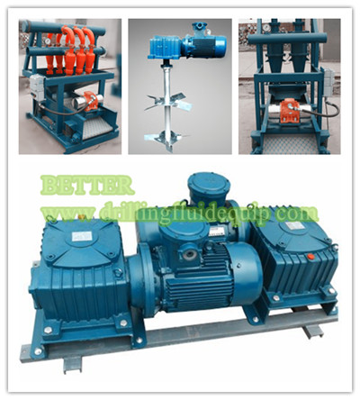
JBQ series mud Agitator, Less than 5.5 kW drilling mud Agitator adopts the blender cycloid speed reducer, and it is applied to the drug liquids mixing tank. This mud agitator has the advantage of compact structure so it occupies small area. More than 7.5 kW Mud Agitator uses the turbo and worm gear speed reducer, with the large torque transmission、 the revolution is steady、it works reliablely and has great merit. Common model of mud agitator is JBQ5.5kW 、JBQ7.5kW 、JBQ11kW and JBQ15kW.The drilling mud agitator is an important components for GN Solids Control drilling fluids processing system.
GN Solids Control as a professional manufacturer for soilds control equipments, we have designed lots of high-quality products, and JBQ series Agitator is one of them. To keep both the mud uniformity and the suspension of solids, the mud agitator is used to agitate the mud consecutively and reliably.This agitator agitates the mud to make cuttings, silt and sand pass the solids control system without being precipitated onto the tank bottom. Due to the simplex turbine decelerator, this product is featured by compact construction, light weight, balanced transmission, low noise, high efficiency of transmission and strong agitating power. Therefore, it is a reliable product in the solids control system.
China manufacturer GN Solids Control offer the world with drilling mud agitator equipments.We are an exporter of drilling fluid mud agitator for Indian, Russian,middle east.etc..Our factory and company are Quality Management System ISO 9001-2000 certified.GN Solids Control operate international oil gas drilling mud separation system sales,service,manufacturing,distribution serivce.Buy drilling fluid mud agitatorfrom China manufacturer.Your best mud agitator for drilling mud circulation system.

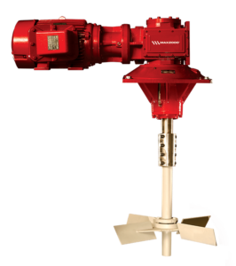
The skid mounted MA-RG agitator is compact, and its low profile reduces headroom requirements and provides more layout space on top of the tanks. The gearbox is a triple-reduction helical-bevel gear drive system that reduces the rotational speed of the motor to drive the impeller(s). Up to 95% mechanical efficiency helps reduce horsepower requirements.
Impellers are available with flat blades (radial flow), contour blades (axial flow), and canted blades (radial/axial flow). The impellers are sized according to tank volume and expected duty. Active mud system compartments—such as solids removal sections, mud mixing sections, and slug pits, which need a higher shear force to produce immediate mixing—are another consideration in impeller sizing.
Brightway mainly supplies four serises kind of shale shaker screens applied to shale shaker, desilter, desander, and mud cleaner. Composite material shaker screen ,Steel Frame Shaker Screen ,Pyramid Shale Shaker Screen,Hook Strip Flat Shaker Screen.
Mud Tank Suction Valves & Dump Valves is the mud control equipment installed in the inside of mud tanks or water tanks. It is used to import mud or liquid phase and prevent different nature of mud or liquid in both side of mud tank to mix with each other.

BETTER produce high-efficiency mud agitator, equivalent to BRANDT™ Agitators MA series, its rugged design, simplicity and dependability have made it the preferred choice of a majority of operators and contractors.

Brandt agitators serve the drilling industry with quality, time- Vertically mounted agitators mount the motor in line with the proven mechanical agitation. The Brandt horizontally mounted gear reducer and output shaft. The explosion-proof, C-face MA™-series agitator has been the industry standard for many motor bolts on and couples to the double reduction helical years. Its rugged design, simplicity and dependability have gearbox. The entire assembly bolts to a fabricated steel base made it the preferred choice of a majority of operators and plate, which is mounted on the mud pit. contractors. The low profile of Brandt horizontal agitators reduce Vertically mounted agitators are lighter than right- headroom requirements. They come in two styles. angle-drive horizontal units, but produce the same mixing Brandt’s original MA™ series with 30:1 single results. In some instances horsepower requirements are reduction worm-gear drive that uses a sliding action worm and reduced due to the 95% efficiency of the helical gearing. gear. Available in 3, 5, 7.5, 10,15, 20, 25, and 30 HP. Impellers Brandt’s new MA-RG (Right Angle Gear) double Brandt agitators are available with three types of reduction,helical gear designed primarily for applications impellers and are sized according to tank volume and expected requiring more than 15 horsepower can be used for large duty. Active mud system compartments (such as solids displacement applications. Up to 95% mechanical efficiency removal sections, mud mixing sections and slug pits) need a helps reduce horsepower requirements compared to conven- higher shear blade to produce more immediate mixing. tional designs. Therefore Brandt recommends either a flat blade or canted The 1:1 ratio of height-to-width of both designs blade, depending on tank depth. Bulk storage compartments results in a low center of gravity, providing stability and safety. need a low-shear blade that maintains suspension in a gentler Brandt VMA™series (Vertical Mechanical Agitator) is manner. ideal for installations with limited footprint availability. These For active mud system compartments less than 5 feet double-reduction, inline, helical gear agitators provide smooth, in height, a flat blade impeller can be used to induce radial flow vibration-free operation and efficient mixing, just like right-angle patterns in the mud. Flat bladed impellers should be placed Brandt agitators. approximately six inches above the tank or two inches above the bottom shaft stabilizer, if one is used. Brandt Agitators™
When compartment height is greater than 5 feet, either a 60- Regardless of what style agitator or impeller is used, properdegree canted impeller, or a high volume contour blade is used sizing is critical. Impeller sizes are determined by calculatingto promote axial as well as radial flow. Canted impellers should the TOR (Turn Over Rate) for each agitated compartment. TOR isbe placed on the shaft so that the distance between the bottom of the time required, in seconds, to completely move the fluid in athe tank and the lower edge of the impeller blades is equal to ¾ mud tank and can be calculated by knowing the tank volume andthe diameter of the impeller. For tanks deeper than 12 feet, two impeller displacement.or more impeller blades may be used in combination. Vt TOR = × 60 For bulk storage tanks, high-efficiency, contour Dimpellers are best. This variable pitch impeller reduces Vt = Tank volume gallonshorsepower requirements and induces less shear to the mud. D = Impeller displacement in gpm (as calculated Shafts by Brandt engineering staff and displayed in chart above) Manufactured of solid mild steel, the agitator shaft is For tanks sized to metric specificationscoupled to the gear reduction assembly with a rigid coupling. All Vt = Tank volume litersshafts are keyed at the bottom for adjustment of impeller height. D = Impeller displacement in lpm (as calculatedA bottom end stabilizer is supplied when tank depths exceed 6 by Brandt engineering staff and displayed in chart above)feet. The stabilizer reduces side loading and protects the agitator For 60-degree canted blade applications TOR shouldwhen auxiliary equipment is carried inside the mud tanks during be between 40 and 90 seconds. As the TOR approaches 40rig moves. seconds, the chance for air entrainment increases. At TOR greater than 90 seconds, proper suspension may be jeopar- T Y P I C A L T U R N O V E R R A T E P E R C O M P A RT M E N T dized and solids will begin to settle. SHAKER INTERMEDIATE SUCTION RESERVE PILL For contour blade applications, TOR must be signifi- Canted 50- 75 50- 75 65- 85 50- 80 40- 65 Impeller cantly faster to achieve the same results, but because of the Contour 25- 38 25- 38 32- 42 25- 40 20- 32 100% axial flow, air entrainment is not a problem. Blade Brandt Agitators™
Model HP Length Height Width Min. Impeller Shaft Shaft Agitator Length Height Width Min. Shaft Shaft Agitator (in) (in) (in) Dia. (in) Diameter Wt. Less Shaft (mm) (mm) (mm) Impeller Diameter Wt. Less Shaft Canted - Contour (in) (lbs/ft) & Impeller Dia. (mm) (kg/m) & Impeller Wt. (lbs) (mm) Wt. (kg)MA3 3 35 1/4 15 11/16 19 9/16 24 28 1 3/4 8 1/4 406 895 398 497 610 44 12 184MA5 5 40 1/4 16 3/4 21 9/16 28 34 2 3/8 15 580 1022 425 548 711 60 22 263MA7.5 7.5 52 1/8 24 1/4 27 5/8 32 38 2 3/8 15 1200 1324 616 702 813 60 22 544MA10 10 52 1/8 24 1/4 27 5/8 32 42 3 24 1224 1324 616 702 813 76 36 555MA15 15 52 1/8 24 1/4 27 5/8 36 48 3 24 1320 1324 616 702 914 76 36 599MA20 20 61 1/4 27 1/8 34 1/4 40 52 3 1/4 28 1898 1556 689 870 1016 83 42 861MA25 25 68 5/8 30 7/8 39 1/2 40 60 3 1/2 32 3/4 3130 1743 784 1003 1016 89 49 1420MA30 30 68 5/8 30 7/8 39 1/2 40 64 3 1/2 32 3/4 3180 1743 784 1003 1016 89 49 1442
Brandt agitators provide more thorough mixing of pits and Contact Brandt for proper agitator sizing. eliminate the problems associated with mud guns, such as Specifications are subject to change without prior notice particle degradation and gun nozzle washout. Brandt agitators can be sized to fit any mud system or type of duty. From Flowline To Disposal, Brandt has the solution to your separation and waste management Western Hemisphere Eastern Hemisphere Phone: (713) 856-4100 Phone: 44-1224-343600 problems. We are one of the Varco Companies; technology Fax: (713) 856-4133 Fax: 44-1224-343700 leaders to the drilling industry. www.varco.com brandt-rigtech-uk@varco.com This is not a complete list of all locations. Call for the location nearest you.
Copyright 2003 Varco International, Inc.Publication date: August 21, 2003Brandt is a registered trademark of Varco International, Inc.All other product, brand, or trade names used in this publication are the trademarks or registeredtrademarks of their respective owners.All rights reserved. This publication is the property of, and contains information proprietary to VarcoInternational, nc. No part of this publication may be reproduced or copied in any form, or by anymeans, including electronic, mechanical, photocopying, recording or otherwise, without the priorwritten permission of Varco International, Inc.Information in this manual is subject to change without notice.
WarrantyBrandt warrants that, for a period of one year from the date of delivery equipment ofBrandt manufacture, the Equipment shall be free of defects in materials andworkmanship under normal use and service, and provided the Equipment is used andmaintained in accordance with instructions supplied by Brandt. This is Brandt"s soleand exclusive warranty. If a defect in the Equipment appears within one year from thedate of shipment, and Purchaser has given written notice of such defect within thirtydays from the discovery thereof, Brandt will repair or replace the part, at its option, byshipping a similar part FOB shipping point or, at its option, refund an equitable portionof the purchase price. Brandt may require the return, to a designated Brandt location,of the defective part, transportation prepaid to establish Purchaser"s claim.No allowance will be made for repairs undertaken without Brandt"s written consent orapproval.This warranty applies only to equipment manufactured by Brandt. Warranties onequipment manufactured by others, if any, are assigned to Purchaser by Brandt(without recourse) at time of delivery. Any description of Equipment, drawings,specifications, and any samples, models, bulletins, or similar material, used inconnection with this sale are for the sole purpose of identifying the Equipment and arenot to be construed as an express warranty that the Equipment will conform to suchdescription. Any field advisory or installation support is advisory only. The foregoingwarranties are in lieu of all other warranties, whether oral, written, express, implied orstatutory. Implied warranties or merchantability and fitness for a particular purposewill not apply. Brandt"s warranty obligations and purchaser"s remedies thereunder aresolely and exclusively as stated herein. Purchaser"s sole and exclusive remedy,whether based upon warranty, contract or tort, including negligence, will be to proceedunder this warranty.All liability of Brandt shall terminate one year from the date of delivery of theEquipment.
Intended audienceThis manual is intended for use by field engineering, installation, operation, and repairpersonnel. Every effort has been made to ensure the accuracy of the informationcontained herein. Brandt, a Varco company, will not be held liable for errors in thismaterial, or for consequences arising from misuse of this material.
Figures provide a graphical representation of equipment components or screensnapshots for use in identifying parts or establishing nomenclature, and may or maynot be drawn to scale.For more specific component information pertinent to your rig configuration, see thetechnical drawings included with your Varco documentation.
Safety requirementsBrandt equipment is installed and operated in a controlled drilling rig environmentinvolving hazardous operations and situations. Proper service and repair is importantfor safe and reliable operation. Operation and service procedures provided by Brandtmanuals are the recommended methods of performing those operations.To avoid injury to personnel or equipment damage, carefully observethe following safety requirements.
Local codes may apply. Please consult them prior to performing any operation.The presence of a Brandt representative at the site does not relieve the owner/operator of responsibility to follow published installation, operation, and maintenanceinstructions.The equipment discussed in this manual may require or contain one or more utilities,such as electrical, hydraulic, pneumatic, or cooling water.Before installing or performing maintenance or repairs on equipment,read the following instructions to avoid endangering exposed personsor damaging equipment.
IntroductionHMA series agitators are heavy-duty mechanical mixers for viscous fluids speciallydesigned for seal type tanks. Several models are available to meet a variety of mixingneeds.The naming convention for these models is:HMA-Xwhere X = the horsepower of the unit. For example, HMA-20 is the 20 hp mud agitatorfor seal type tanks.Each HMA series agitator uses a pipe-spool shaft and impeller(s) to maintain ahomogeneous mixture of liquids and solids within a tank. Impellers have contourblades (axial flow), and may be installed in multiple configurations to provide thedesired results. The impeller shaft is suspended from and attached to the output shaftof the low-profile, skid-mounted gearbox. The gearbox uses a worm-worm gear drivesystem to reduce the rotational speed of the explosion-proof motor to drive theimpeller(s).HMA series agitators are available in models ranging from 25 to 40 horsepower, andcan be seal base unit or shaft seal units. Impellers range from 54 inches (1372 mm)diameter to 84 inches (2134 mm) diameter.
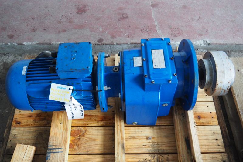
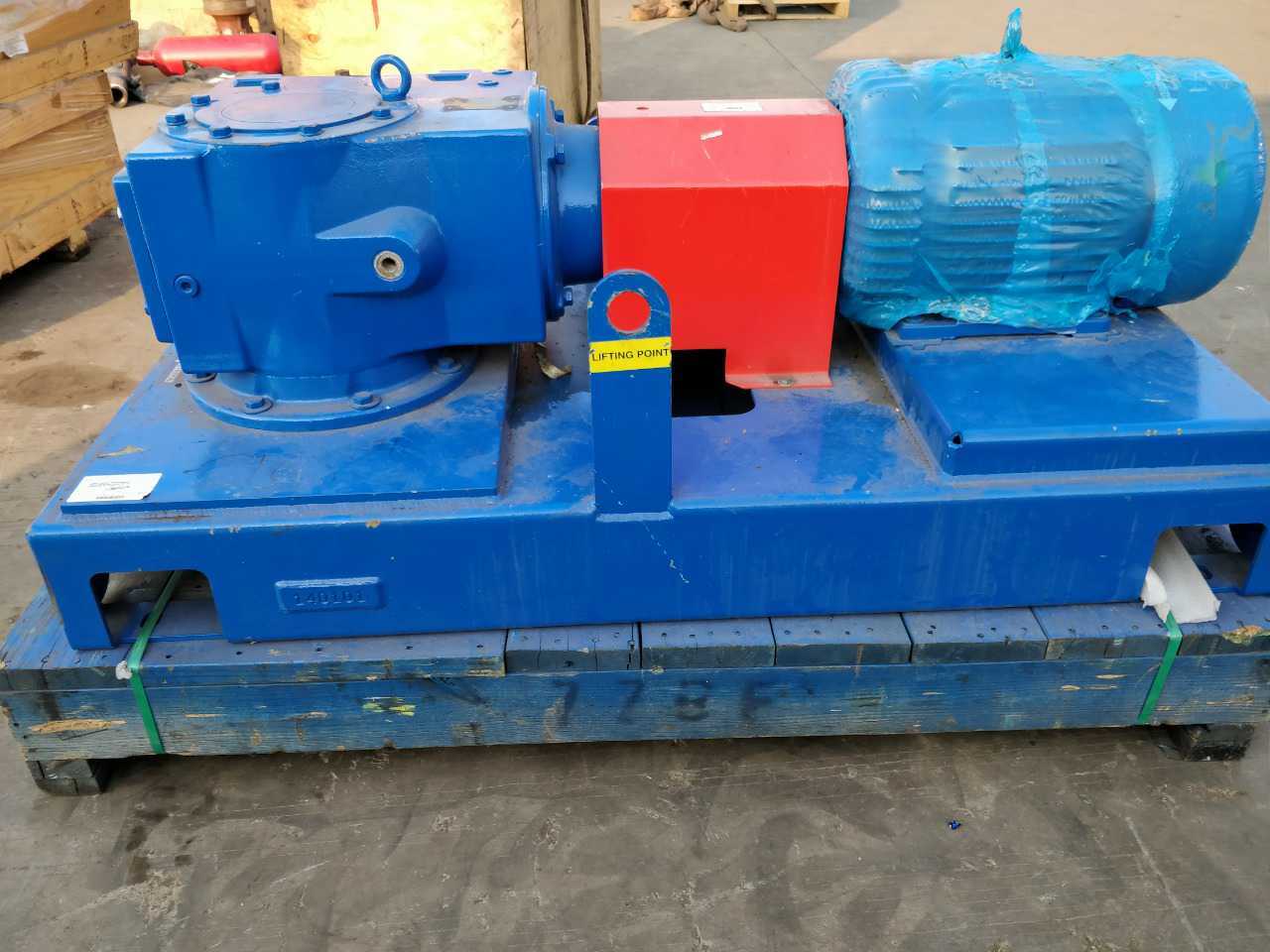
MotorThe motors used on Brandt mud agitators are explosion proof, T-frame, three-phaseelectric motors directly coupled to the gearbox using a flexible coupling with a solidsteel guard. Motors are available for most voltage/frequency requirements. Otherelectrical code styles and temperature ratings are also available.
GearboxThe gearbox is a triple reduction worm-worm gear drive, reducing the motor speed(900 rpm @ 60 Hz) to the agitator speed (30 rpm) in a single 30:1 reduction. Thegearbox contains an output shaft, two seals, and four to six bearings in addition to theworm-worm gear. The bearings are spaced to minimize shaft vibration and deflection,and seals are readily obtainable standard sizes. Unlike many competing agitators,Brandts gearbox requires no manual lubrication of the bottom output bearing.
ImpellerImpellers are contour blade style, and may be installed in multiple configurations toprovide the desired results.Impellers range from 54 inches (1372 mm) to 84 inches (2134 mm) in diameter.Larger custom-designed blades and mixing systems are also available. See Chapter8 to find the Brandt office nearest you.Impeller speed is 30 rpm for 60 Hz applications.
Contour-blade impellersOn contour blade impellers (Figure 2-1), the blades are designed with a variable pitchreducing the horsepower requirements and inducing less shear to the mud. Contourblades move liquid downward to the bottom of the tank, along the tank bottom towardthe tank walls, and then up the tank wall. All fluid in the tank is mixed continuously,and the same consistency is maintained in all parts of the tank.Field experience has confirmed that this design provides the most homogeneousmixture in the widest range of installations. Fluid agitation minimizes fluid controlproblems caused by inconsistent mixtures.
Impeller shaftHMA standard impeller shafts are manufactured of eight-inch pipe spools. Theimpeller shaft is coupled to the gearbox with a rigid coupling.Shaft length is determined by tank depth. When ordering impellershafts, always specify the actual tank depth. Tank depth is defined asthe distance from the bottom of the tank to where the agitator ismounted.
Bottom shaft stabilizerA bottom shaft stabilizer is required to reduce side loading on the gearbox bearings.The stabilizer also protects the agitator shaft and impeller when auxiliary equipment iscarried inside the mud tank during rig moves.
There are several options available for HMA-series units. Popular options includespecial paint finishes, remote starters, other electrical controls, and special dutymotors. Contact your Brandt sales representative to discuss which options may beright for your application. See Chapter 8 to find the Brandt office nearest you.
2. Impeller rotation: The impeller should rotate clockwise when viewed from top.3. Oil fill/breather plug: plug must be clear of any obstruction to prevent pressurebuild-up and possible seal damage.4. Agitator should operate with no vibration.5. Check rubber insert on input shaft coupling for wear and cracks.6. For optimal performance, change the oil after the first five days of operation.
1. Inspect for oil leaks.2. Keep motors clean and ventilation opening clear of mud build-up or otherdebris.3. Check impeller shaft coupling for proper make-up.
—–Liners——Mission Ceramic Liner——Mission Supreme Liner—–Piston Rods——Blak-JAK HydrA-LIGN Piston Rod System——Mission Self Aligning Piston Rod—–Pistons——Mission Green Duo Piston——Mission Slip Seal Bullitt Piston——Mission Supreme Piston——Mission Blue Lightning Piston——Mission White Lightning Bonded Piston——Mission White Lightning Slip Seal Piston—–Valves and Seats——Mission FK-1 Valve——Mission FK-N Valve——Mission Roughneck™ and Roughneck™ HP——Mission Service Master II——Mission Silver Top Valves and Seats——Mission Super Service Vavles and Seats——Service Master Drilling Valve——Supreme Valve and Seat—–Fluid End Modules and Accessories——Fluid End Accessories——-Blak-JAK Torque Pro——-Blak-JAK Torque Pro Lite——-Mission Bushing X-tractor——Liner Retention Systems——Modules (Mission L 7500 Module)—–Fluid Transfer Systems——Brine Filtration System——Centrifugal Pump Unitization Configurations——Custom Cooling Solutions——High Pressure Wash down Systems——NOV Mission Potable/Sanitary Water Pressure Sets——Resources—–Handling Tools——Adapter Rings——Air Operated Elevators——-A-Series Collar Type——-G-Series 18 Degree Center Latch——-Y-Series Slip Type——BHAT——Bushings——-Casing Bushings——-Casing Spiders——-MBH 1250——-MDSP Series——-MPCH Series——-MSPC Series——-MSP Series——-Roller Kelly Bushings——Casing Running Tools——-CRT 350 and 500 Casing Running Tool——Custom Dies and Inserts——Elevator Spiders and FMS——-BJ-250——-BJ-350——-FMS-275——-FMS-375——-V-1000——-V-500——-V-750——Hydraulic Elevators——-BX-3——BX-4-35——BX-4-50——BX-4-75——BX-5——BX-7——BXS Series——H-SJH Type——UX Horse Shoe——Links——-Perfection Links——-Weldless Links——Manual Elevators——-A-Series Collar Type——-DC Dolly——-G-Series 18 Degree Center Latch——-S-Series Auxiliary——-SBX7——-X-Series Collar Type Side Door——-Y-Series Slip Type——Manual Tongs——-HT Manual Tongs——Power Slips——-Power Slip Frame——-PS-15 Power Slip——-PS-16 Power Slip——-PS-21 Power Slip——-PS-30 Power Slip——-PF495 Power Slip——-SLT——Power Tools——-KS-6600——-KS-6800——-SSW-30——-SSW-40——-TW-61 Hydraulic Torque Wrench——Rotary Support Tables——-RST375——-RST495——-RST495 False——-RST495 Heavy——-RST495 Without Slip Ring——-RST605——-RST605 False——-RST605 Heavy——-RST605 Without Slip Ring——-RST755 Without Slip Ring——Slips——-CMS-XL——-DCS Series——-MP Series——-SD Series——-Type C——-UC-3——Resources——-BX Elevators TMS 1 of 2——-BX Elevators TMS 2 of 2——-Handling Tools TMS——-Rotary Support Table TMS—–Hoisting——Drawworks——-AHD Drawworks——–AHD-1000 Active Heave Drilling Drawworks——–AHD-1250 Active Heave Drilling Drawworks——–AHD-500 Active Heave Drilling Drawworks——–AHD-750 Active Heave Drilling Drawworks——-Drilling Drawworks——–AC Gear Driven Drawworks———ADS-10T AC Electric Gear Driven Drawworks———ADS-30Q AC Electric Gear Driven Drawworks———SSGD-1000 AC Gear Driven Drawworks———SSGD-1250 AC Gear Driven Drawworks———SSGD-360 AC Gear Driven Drawworks———SSGD-500 AC Gear Driven Drawworks———SSGD-750 AC Gear Driven Drawworks——–DC Chain Driven Drawworks———1625-UDBE DC Chain Driven Drawworks—–Iron Roughnecks——AR3200 Automated Iron Roughneck——HydraTong™ ARN-270——HydraTong™ MPT-270——Iron Roughneck Accessories——-Casing Module——-Hydraulic Mud Bucket——-Pipe Doper System——Resources——ST 100 Iron Roughneck——ST-120 Iron Roughneck——ST-160 Iron Roughneck——Jacking and Skidding——-Jacking Systems——-Jacking Claw Skidding Systems——-Rack and Pinion Skidding Systems——-Toggle Gripper System ——Lifting and Handling——-Market Segments——–Construction———SUBSEA CONSTRUCTION VESSEL———PIPELAY AND CABLELAY VESSEL———WINDMILL INSTALLATION VESSEL———CRANE VESSEL/ LIFT BOAT———IMR / WELL INTERVENTION VESSEL———ANCHOR HANDLING VESSEL——–Drilling———DRILLSHIP———JACK UP———SEMI SUBMERSIBLE———-FPSO/FPS———-SEMI SUBMERSIBLE/ SPAR/ TLP———-JACKET/ FIXED INSTALLATION——–Production———-FPSO/FPS———-SEMI SUBMERSIBLE/ SPAR/ TLP———-JACKET/ FIXED INSTALLATION——-Product Catalogue——–Anchor Handling Systems———Anchor Handling and Towing Winch———Anchor Handling Equipment Package———Secondary Winch——–Cranes———Next Generation Subsea Knuckle Boom Cranes———Box Boom Cranes———-Knuckle Boom Crane———-Single Boom Crane———-Telescopic Boom Crane———Lattice Boom Cranes———-Around the Leg Crane———-DNS Crane———-MSB Crane———-OC L Crane———-Unit Crane———Heavy Lift Cranes———-Around the Leg Crane———-MSB Crane———-Post Crane———-Tub Mounted Crane———Other Cranes———-A-Frame———-Stevedoring Cranes———Subsea Cranes———-Subsea Box Boom Crane———-Subsea MSB Crane——–Hose Loading Stations——–Mooring Systems———Mooring System for Drilling Units———Mooring System for Production Units——–Pipe Lay and Cable Lay Systems———Cable Lay Systems———Pipe Lay Systems———Tensioner———Upending Control Systems——–Riser Pull In Systems——Motion Compensation——-Crown Mounted Compensators (CMC)——-Direct Line Compensators (DLCs)——-Drill String Compensators (DSCs)——-N-Line Tensioner system——-Resources——-Tensioners——Offshore Units——-Drillship——-Fixed Platforms——-Jackup Rig——-Semi-submersible——-Well Intervention——Pipe Handling——-Horizontal Pipe Handling——–Catwalk Machines——–Catwalk Shuttle——–Pipe Deck Machines (PDM)——–Pipe – Riser Gantry Cranes——–Pipe Transfer Conveyor (PTC)——–PipeCat™ Laydown System——–Robotic Arms———DFMA-P——–DFMA-U——–UHT——-Horizontal-To-Vertical Pipe Handling——–Custom Dies and Inserts——–Hydraulic Mousehole——–Service and Access Baskets——-Pipe Handling Accessories——-Pipe Handling Cranes——-Resources——-Vertical Pipe Handling——–Racking Systems———PRS 4i/HR III———PRS5,6/HR IV———PRS8i and Hydraracker XY (HRXY)——–Standguard——Power Systems——-Hydraulic Power Units——-Motors——-Resources——-Energy Recovery——–Rotary Tables——Rotating Equipment——Structures——-Derricks——Top Drive Systems——-Fixed Electric Top Drives——-Resources——-Washpipe Systems


 8613371530291