
mud agitator manual brands
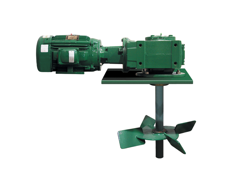
Our agitators feature the new dracomet coated corrosion resistant keyless coupling for easy installation and impeller adjustment. The units come complete with base plate, motor, gearbox, impeller, shaft & couplings.
As an SPX FLOW brand, Lightnin serves the challenging waste and water treatment sector, as well as the processing of solvents, fertilizers, food/beverages, pharmaceuticals and biofuels. The mixers and agitators, that are custom designed and fabricated, are used for equalization, neutralization, flocculation, aeration, sludge mixing, flash mixing and general blending purposes. The Lightnin industrial mixer portfolio covers both portable and larger fixed-mount units. All Lightnin equipment is designed to provide prolonged trouble-free operation regardless of the specific application demands. Through the proprietary gearbox and impeller technologies developed in recent times, we can offer the market advanced mixing solutions that are far more compact and power-efficient than ever before. They also have significantly greater operational lifespans, thanks to anti-fouling mechanisms and other state-of-the-art features. Consequently, customers are able to raise their productivity levels and avoid costly downtime issues, while also keeping the energy consumption involved to an absolute minimum.

This design allows for the efficient extraction of drilling mud gasses and control of the sample collection chamber. This is an improvement over other extractors that act much as a centrifugal pump and spit drilling mud from the side. The long vertical tubing also acts as a condensation tower that helps eliminate much of the water vapor in the extracted sample.
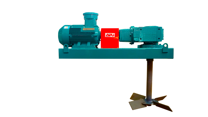
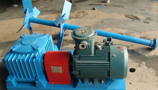
1. Use worm / worm speed reducer; Compact structure, good meshing performance, reliable operation.; 2. With the combination of the reducer and explosion-proof motor, suitable for harsh conditions in the field of work.; 3. Explosion-proof motor and reducer input shaft through the elastic coupling directly, without the use of belt transmission, so the speed of mixing impeller constant.; 4. Stirring intensity and wide range, and from the structural design avoid the motor at the start of the current overload phenomenon.; 5. Explosion-proof motor level placement, installation, adjustment or replacement is very convenient.JB/W series agitator is an important equipment of drilling fluid solid control system, which is mainly used for mixing drilling fluid to prevent the drilling fluid solid particles from settling in the circulation process, and make the drilling fluid mix evenly and stably.

5W 7.5W 15W motor / gear-box Drilling Mud Mixing Industrial mud tank mud Agitators 5W 7.5W 15W motor / gear-box Drilling Mud Mixing Industrial mud tank mud Agitators 5W 7.5W 15W motor / gear-box Drilling Mud Mixing Industrial mud tank mud Agitators 5W 7.5W 15W motor / gear-box Drilling Mud Mixing Industrial mud tank mud Agitators 5W 7.5W 15W motor / gear-box Drilling Mud Mixing Industrial mud tank mud Agitators 5W 7.5W 15W motor / gear-box Drilling Mud Mixing Industrial mud tank mud Agitators 5W 7.5W 15W motor / gear-box Drilling Mud Mixing Industrial mud tank mud Agitators 5W 7.5W 15W motor / gear-box Drilling Mud Mixing Industrial mud tank mud Agitators 5W 7.5W 15W motor / gear-box Drilling Mud Mixing Industrial mud tank mud Agitators 5W 7.5W 15W motor / gear-box Drilling Mud Mixing Industrial mud tank mud Agitators 5W 7.5W 15W motor / gear-box Drilling Mud Mixing Industrial mud tank mud Agitators 5W 7.5W 15W motor / gear-box Drilling Mud Mixing Industrial mud tank mud Agitators 5W 7.5W 15W motor / gear-box Drilling Mud Mixing Industrial mud tank mud Agitators 5W 7.5W 15W motor / gear-box Drilling Mud Mixing Industrial mud tank mud Agitators 5W 7.5W 15W motor / gear-box Drilling Mud Mixing Industrial mud tank mud Agitators 5W 7.5W 15W motor / gear-box Drilling Mud Mixing Industrial mud tank mud Agitators 5W 7.5W 15W motor / gear-box Drilling Mud Mixing Industrial mud tank mud Agitators
Oil ang gas drilling (Drilling mud recycling system, drilling waste management, comprehensive disposal for oil sludge, mud comprehensive treatment station, barite recovery system etc.)
Infrastructure construction (HDD mud purification, pipe jacking / TBM slurry circulation, slurry for continuous wall construction’s separation, and mud of pile foundation engineering’s treatment, etc.);

© Copyright 2003 Varco International, Inc. Publication date: August 21, 2003 Brandt is a registered trademark of Varco International, Inc. All other product, brand, or trade names used in this publication are the trademarks or registered trademarks of their respective owners. All rights reserved. This publication is the property of, and contains information proprietary to Varco International, nc. No part of this publication may be reproduced or copied in any form, or by any means, including electronic, mechanical, photocopying, recording or otherwise, without the prior written permission of Varco International, Inc. Information in this manual is subject to change without notice.
Intended audience This manual is intended for use by field engineering, installation, operation, and repair personnel. Every effort has been made to ensure the accuracy of the information contained herein. Brandt®, a Varco company, will not be held liable for errors in this material, or for consequences arising from misuse of this material.
Conventions Notes, cautions, and warnings Notes, cautions, and warnings appear throughout this manual to provide you with additional information, and to advise you to take specific action to protect personnel from potential injury or lethal conditions. They may also inform you of actions necessary to prevent equipment damage or conditions that may void your warranty. Please pay close attention to these advisories.
Safety requirements Brandt equipment is installed and operated in a controlled drilling rig environment involving hazardous operations and situations. Proper service and repair is important for safe and reliable operation. Operation and service procedures provided by Brandt manuals are the recommended methods of performing those operations. To avoid injury to personnel or equipment damage, carefully observe the following safety requirements.
Local codes may apply. Please consult them prior to performing any operation. The presence of a Brandt representative at the site does not relieve the owner/ operator of responsibility to follow published installation, operation, and maintenance instructions. The equipment discussed in this manual may require or contain one or more utilities, such as electrical, hydraulic, pneumatic, or cooling water. Before installing or performing maintenance or repairs on equipment, read the following instructions to avoid endangering exposed persons or damaging equipment.
Maintenance Equipment must be maintained on a regular and routine basis. See the service manual for maintenance recommendations. Failure to conduct routine maintenance could result in equipment damage or injury to personnel.
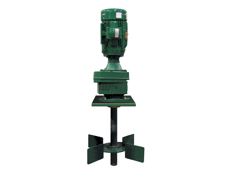
Introduction HMA series agitators are heavy-duty mechanical mixers for viscous fluids specially designed for seal type tanks. Several models are available to meet a variety of mixing needs. The naming convention for these models is: HMA-X where X = the horsepower of the unit. For example, HMA-20 is the 20 hp mud agitator for seal type tanks. Each HMA series agitator uses a pipe-spool shaft and impeller(s) to maintain a homogeneous mixture of liquids and solids within a tank. Impellers have contour blades (axial flow), and may be installed in multiple configurations to provide the desired results. The impeller shaft is suspended from and attached to the output shaft of the low-profile, skid-mounted gearbox. The gearbox uses a worm-worm gear drive system to reduce the rotational speed of the explosion-proof motor to drive the impeller(s). HMA series agitators are available in models ranging from 25 to 40 horsepower, and can be seal base unit or shaft seal units. Impellers range from 54 inches (1372 mm) diameter to 84 inches (2134 mm) diameter.
Motor The motors used on Brandt mud agitators are explosion proof, T-frame, three-phase electric motors directly coupled to the gearbox using a flexible coupling with a solid steel guard. Motors are available for most voltage/frequency requirements. Other electrical code styles and temperature ratings are also available.
Gearbox The gearbox is a triple reduction worm-worm gear drive, reducing the motor speed (900 rpm @ 60 Hz) to the agitator speed (30 rpm) in a single 30:1 reduction. The gearbox contains an output shaft, two seals, and four to six bearings in addition to the worm-worm gear. The bearings are spaced to minimize shaft vibration and deflection, and seals are readily obtainable standard sizes. Unlike many competing agitators, Brandt’s gearbox requires no manual lubrication of the bottom output bearing.
Contour-blade impellers On contour blade impellers (Figure 2-1), the blades are designed with a variable pitch reducing the horsepower requirements and inducing less shear to the mud. Contour blades move liquid downward to the bottom of the tank, along the tank bottom toward the tank walls, and then up the tank wall. All fluid in the tank is mixed continuously, and the same consistency is maintained in all parts of the tank. Field experience has confirmed that this design provides the most homogeneous mixture in the widest range of installations. Fluid agitation minimizes fluid control problems caused by inconsistent mixtures.
Impeller shaft HMA standard impeller shafts are manufactured of eight-inch pipe spools. The impeller shaft is coupled to the gearbox with a rigid coupling. Shaft length is determined by tank depth. When ordering impeller shafts, always specify the actual tank depth. Tank depth is defined as the distance from the bottom of the tank to where the agitator is mounted.
Bottom shaft stabilizer A bottom shaft stabilizer is required to reduce side loading on the gearbox bearings. The stabilizer also protects the agitator shaft and impeller when auxiliary equipment is carried inside the mud tank during rig moves.
The greases shown in this manual are given as examples of appropriate greases. Any other grease that meets the standards of the National Lubricating Grease Institute (NLGI) is acceptable.
2. Impeller rotation: The impeller should rotate clockwise when viewed from top. 3. Oil fill/breather plug: plug must be clear of any obstruction to prevent pressure build-up and possible seal damage. 4. Agitator should operate with no vibration. 5. Check rubber insert on input shaft coupling for wear and cracks. 6. For optimal performance, change the oil after the first five days of operation.
1. Inspect for oil leaks. 2. Keep motors clean and ventilation opening clear of mud build-up or other debris. 3. Check impeller shaft coupling for proper make-up.

Manual Comments on the manual for this equipment: _____________________________________________________________________________ _____________________________________________________________________________ _____________________________________________________________________________
Chapter 3: Installation Installation . . . . . . . . . . . . . . . . . . . . . . . . . . . . . . . . . . . . . . . . . . . . . . . . . . . . . . . . . . . . . Agitator Safety Flow Diagram. . . . . . . . . . . . . . . . . . . . . . . . . . . . . . . . . . . . . . . . . . . . . Familiarise with GA"s and Scope of Work . . . . . . . . . . . . . . . . . . . . . . . . . . . . . . . . . . . Review the Installation Manual. . . . . . . . . . . . . . . . . . . . . . . . . . . . . . . . . . . . . . . . . . . . Identify the Crates and Review the Packing List . . . . . . . . . . . . . . . . . . . . . . . . . . . . . . Handling . . . . . . . . . . . . . . . . . . . . . . . . . . . . . . . . . . . . . . . . . . . . . . . . . . . . . . . . . . . . . Planning Meeting . . . . . . . . . . . . . . . . . . . . . . . . . . . . . . . . . . . . . . . . . . . . . . . . . . . Risk Assessment . . . . . . . . . . . . . . . . . . . . . . . . . . . . . . . . . . . . . . . . . . . . . . . . . . . To Site . . . . . . . . . . . . . . . . . . . . . . . . . . . . . . . . . . . . . . . . . . . . . . . . . . . . . . . . . . . Unpack . . . . . . . . . . . . . . . . . . . . . . . . . . . . . . . . . . . . . . . . . . . . . . . . . . . . . . . . . . . . . . Component Check . . . . . . . . . . . . . . . . . . . . . . . . . . . . . . . . . . . . . . . . . . . . . . . . . . . . . Inform NOV . . . . . . . . . . . . . . . . . . . . . . . . . . . . . . . . . . . . . . . . . . . . . . . . . . . . . . . . . . Installation - Planning Meeting . . . . . . . . . . . . . . . . . . . . . . . . . . . . . . . . . . . . . . . . . . . .
General Information This manual contains installation, operation, maintenance and parts information. Information in this manual should enable qualified personnel to install, operate and troubleshoot this system. Every effort has been made to ensure the accuracy of the information contained herein. NOV will not be held liable for errors in this material, or for consequences arising from misuse of this material.
Safety Requirements This equipment is installed and operated in a controlled drilling rig environment involving hazardous situations. Proper maintenance is important for safe and reliable operation. Procedures outlined in these manuals are the recommended methods of performing operations and maintenance. To avoid injury to personnel or equipment damage, carefully observe requirements outlined in this section.
General System Safety Practices The equipment discussed in this manual may require or contain one or more utilities, such as electrical, hydraulic, pneumatic, or cooling water. Read and follow the guidelines below before installing equipment or performing maintenance to avoid endangering exposed persons or damaging equipment.
Routine Maintenance Equipment must be maintained on a routine basis. See the service manual for maintenance recommendations. Failure to conduct routine maintenance could result in equipment damage or injury to personnel.
Product Information Introduction Brandt® MA-RG Series Agitators are heavy-duty mechanical mixers for viscous fluids. The gearbox is a helical-bevel gear drive system that reduces the rotational speed of the motor to drive the impeller(s). The impeller shaft is suspended from and attached to the output shaft of the gearbox. Several models are available to meet a variety of mixing needs. The naming convention for these models is: MA-XRG where X = the horsepower of the unit and RG indicates the helical-bevel gearbox. For example, MA-20RG is the 20 hp mud agitator with a helical-bevel gearbox. MA-RG Series Agitators are very compact. Their low profile reduces headroom requirements and provides more layout space on top of the tanks. The 1:1 height-to-width ratio results in a lower center of gravity, providing stability and safety should the impeller encounter a sudden shock load. MA-RG Series Agitators use a mounting skid. An even lower profile version of the MA-RG Series Agitator is offered in which a base plate is used instead of the mounting skid to reduce the overall height. The naming convention for the agitator with a base plate is: MA-XRGLP Another variation of the MA-RG Series Agitators has a C-face motor with a close coupling style. This variation also has a base plate instead of a mounting skid and naming convention is: MA-XRGC For example, the MA-3RGC is the 3 hp mud agitator with a helical-bevel gearbox, a base plate and a C-face motor. Each MA-RG Agitator uses a shaft-mounted impeller to maintain a homogeneous mixture of liquids and solids within a tank. Impellers are available with flat blades (radial flow), contour blades (axial flow), and canted blades (radial/axial flow). Blades may be installed in single or multiple configurations to provide the desired results. There are several options available for MA-RG Series Agitators. Popular options include special paint finishes, remote starters, other electrical controls, and special duty motors. Contact your sales representative to discuss which options may be right for your application. See Chapter 8, titled "Worldwide Locations" to locate the office nearest you.
Unit Description Each MA-RG Agitator consists of a motor, gearbox, mounting base and shaft-mounted impeller. Electrical controls, special coatings, custom bases, and other options are available.
Motor The motors used on the mud agitators are explosion proof, three-phase electric motors directly coupled to the gearbox using a flexible coupling with a solid steel guard. Motors are available for most voltage/frequency requirements. Other electrical code styles and temperature ratings are also available.
Gearbox The gearbox is a triple-reduction helical-bevel gear drive reducing the motor speed (1800 rpm @ 60 Hz / 1500 rpm @ 50 Hz) to the agitator speed (60 rpm / 50 rpm respectively) in a 30:1 nominal reduction. The actual output speed varies by motor and gearbox size. The gearbox contains an output shaft, two seals, and four to six bearings in addition to the helicalbevel gear system. The bearings are generously spaced to minimize shaft vibration and deflection. Seals are standard sizes readily obtainable.
Contour-blade Impellers On contour blade impellers (see Figure 2-3), the blades are designed with a variable pitch reducing the horsepower requirements and inducing less shear to the mud. Contour blades move liquid downward to the bottom of the tank, along the tank bottom toward the tank walls and then up the tank wall. All fluid in the tank is mixed continuously and the same consistency is maintained in all parts of the tank. Field experience has confirmed that this design provides the most homogeneous mixture in the widest range of installations. Complete fluid agitation minimizes fluid control problems caused by inconsistent mixtures. Contour blades also use less horsepower than canted blades.
Multiple Impellers When an agitator is used in an extremely deep tank, over 15 feet (4.5 m) deep, multiple impellers can be mounted on one shaft. Usually the upper impeller(s) is a canted or contour blade and the bottom impeller is a flat blade. A bottom shaft stabilizer is often required for multiple impellers. Contact our engineering department for proper impeller sizing and stabilizer requirements. See Chapter 8, titled "Worldwide Locations" to locate the office nearest you.
Impeller Shaft Standard impeller shafts for MA-RG Series Agitators are manufactured of solid mild steel. The impeller shaft is coupled to the gearbox with a rigid coupling. All shafts are keyed to adjust the height of the impeller. Shaft length is determined by tank depth. When ordering impeller shafts, always specify the actual tank depth. Tank depth is defined as the distance from the bottom of the tank to where the agitator is mounted.
Bottom Shaft Stabilizer A bottom shaft stabilizer is required in deep tanks to reduce side loading on the gearbox bearings. The stabilizer also protects the agitator shaft and impeller when auxiliary equipment is carried inside the mud tank during rig moves. Bottom shaft stabilizers are required when the tank depth is 8 feet (2.4 m) or more. 12 www.nov.com/brandt
Available Models MA-RG Series Agitators are available in several models from 3 to 40 hp. The following table lists the physical specifications for each agitator model.
Installation Installation Proper installation of the agitator will help ensure proper operation with low level of vibration and long service life. Installation should start at the top with connections then made toward the bottom. Before installing the shafts, all coupling connections must be cleaned of all debris, sand or rust. All connections must be torqued to the manufacturer’s specifications. Do not use grease or anti-seize compound between the connections.
Agitator Safety Flow Diagram The list below illustrates the safe and ideal steps in which to install the agitator. It is therefore recommended that these steps are followed in order that a safe and efficient installation of the equipment will take place.
Familiarise with GA"s and Scope of Work The general arrangement drawings supplied are to be reviewed to assist in the location and orientation of the agitators. All personnel involved in the installation should make themselves aware of the complete scope of the work.
Review the Installation Manual The installers should familiarize themselves and follow the installation procedures contained in this manual. Any issues or questions regarding installation, commissioning or use of the agitators can be addressed by the field service representative.
Identify the Crates and Review the Packing List With the aid of the packing list, each agitator and shaft can be identified readily by the markings on each crate. All crate gross weights are on the crate labels and packing lists.
Handling Planning Meeting For handling the agitator and shaft crates to the site, personnel involved should attend the Planning Meeting to decide on the safest, most direct route to move the agitator and shaft crates into position as close as possible to the final location.
Risk Assessment Risk assess any potential hazard that may lead to serious injury or death when transporting the agitator and shaft crates. Hazards must then be addressed by all key personnel to ensure safe transit of the crates to the site location.
To Site Extreme care must be taken to prevent damage when moving the agitator and shaft crates. Ideally, the use of a spreader bar with soft fabric slings is the recommended support method for lifting. Never lift a crate with only one support point. Only certified sling sets are to be used. Ideally, soft fabric slings should be used to minimise damage to the crates or components. All lifting equipment and procedures must comply with applicable safety requlations.
Unpack Personnel should always unpack the agitator and shaft in an efficient and safe manner providing a clean and safe working environment. The equipment will be delivered to the site in crates. Remove any protective sheeting and steel banding used to secure the crates. Remove the lid and then the sides, taking particular care not to damage the equipment or cause injury to any personnel. Any small loose items should remain in the crates awaiting storage or installation.
Component Check All components enclosed in the agitator and shaft crates are to be thoroughly checked against the packing list to ensure all items have been delivered/received.
Installation - Planning Meeting Planning meeting is to be carried out prior to installation of the agitators and shafts. A clear plan of action is to be deduced involving key personnel on how best to install the agitators and shafts efficiently and safely.
Installation - Risk Assessment All potential hazards that may lead to serious injury or death during the installation process must be taken into account. Hazards must then be addressed by all key personnel to ensure a safe and efficient installation of the agitators and shafts.
Support Structure Adequate support must be made in the deck in order to support the agitator correctly. Suitable structure should be designed based on reaction forces specified on the installation drawings (if applicable included in documentation package) and/or in this manual. The following information should be reviewed and taken into consideration:
Agitator weight and design loads (Refer to table titled "MA-RG Series Models" on page 11 for weights of agitators and table titled "Impeller Shaft Measurements" on page 10 for shaft weights and maximum torque.)
Placement of structural members to allow full contact support for the agitator skid footprint Use of structural members of equal or higher rigidity to the material used in the agitator skid is recommended. Typically I-beams of respective strength in the lateral and horizontal bulk head to bulk head cross sections is sufficient to support the base/skid of the agitator.
Placement of the agitator Directly to the tank deck is recommended. Lowering the mounting height improves the strength of the structure and lowers the center of gravity, improving resistance to vibration.
The agitator frame should be supported by a rigid structure making the first fundamental natural frequency of the whole system 15 % above the operating rotating frequency of the motor and having following characteristics:
The agitator skid has been engineered to have the first natural frequency 50 % or more above the motor operating speed. The natural frequency of the combined rigid structures is different than that of its components as well as dependent on the rigidity of their connection. Verification of the natural frequency of an as-installed structure might be helpful in eliminating any resonance. Should resonance of the combined structure occur, it can be eliminated by modification of either the supporting structure or the rigidity of agitator skid to support structure connection. The system natural frequency is typically directly proportionate to its stiffness. Increasing stiffness will shift the natural frequency up, thus decreasing the possibility of resonance. This can be achieved by: 1. use of rigid, symmetrical and leveled structural support for the agitator base. 2. adding cross members to the support structure. 3. minimizing the gaps between the agitator base and the support structure or closing of the gaps by welding. Minimize the use of shims. 4. minimizing agitator shaft misalignment.
Below is an example of an installation where adequate primary structural support was added to strengthen the deck area in which the agitators were installed.
Please note that sub support frames for the agitator baseplates must be suitably fabricated. Inadequately fabricated support frames can cause instability or vibration issues.
Lifting and Mounting Lifting should be performed with proper lifting equipment and using only the designated agitator lifting points. The agitator should be stored and lifted with its shipping crate until it is ready to be installed in its final destination. The agitator should never be rested on the gearbox output shaft. Once the agitator is in its intended position, check the alignment of the mounting holes and gaps between the agitator skid and support structure as follows:
The gap between the agitator skid and support structure at the bolting points before bolt down should be less than 0.025 in. (0.635 mm). Gaps at the bolting points ranging from 0.025 in. (0.635 mm) to 0.5 in. (12.7 mm) should be eliminated using shims to prevent deflection of the agitator skid and impact on shaft alignment.
If needed, the agitator skid can be permanently welded to the supporting structure to close excessive gaps between the structures. Alternatively, the support frame can be build and fitted to the agitator skid before being welded to the tank deck. Any gaps resulting from unevenness of the tank structure can be closed while welding the support frame. Ensure that the skid is grounded before welding. Failure to do so can result in electrical system damage.
Installation All MA-RG Agitators are supplied as shop assembled agitators. All shaft assemblies are broken down into various separate parts (shaft complete with coupling/bushing assembly, impeller assembly and stabilizer housing) to aid in maneuvering parts into mud pits with restricted access. Two type of shafts are manufactured; either a solid shaft that is keyed for the impeller or a pipe spool to which the impeller is bolted. The solid shaft installation instructions are given followed by the pipe spool installation instruction on page 31.
Mechanical Installation 1. Refer to the "Taper-Lock Coupling Installation Instructions" that is supplied in the "Supporting Documents". These should be reviewed to familiarise the user with the shaft fixing components being used. 2. Before locating the agitator on top of the tank, ensure the surface is square and level. 3. Ensure before installation of the agitator onto the top of the tank, the structure is strong enough to hold the unit and the tank dimensions are correct as per the general arrangement drawings. It is recommended the agitators are bolted to rigid beams. 4. The agitator assembly can be lifted to its location and into place using the four lifting eyes provided on the unit and a correct four leg lifting sling assembly (not supplied). The agitator assembly should be placed on blocks in the exact location it will be secured to give 19.685 in. (500 mm) clearance from the bottom of the tank to the bottom of the shaft assembly when the shaft assembly is fitted to the agitator assembly. This is to ensure the stabilizer will be fitted in the correct location. The agitator assembly and shaft assembly need to be fitted before the stabilizer to ensure correct alignment.
7. If the blades have been removed from the impellers, they need to be reinstalled. Refer to the section titled "Bolt Torque Requirements" on page 102 for the correct torque for the agitator fasteners. 8. When assembling the shafts, it is advisable to use two trestles and set the shaft in between them for ease of assembly. See Figure 3-8.
10. Install the impeller the correct way up. The impeller blades should be oriented so that the fluid is pushed downward when the agitator is rotating clockwise when viewed from the top, i.e. the leading edge of the paddle will be in the higher position with the trailing edge in the lower position. 11. Ensure the bushing key is in the shaft keyway. Slide the impeller onto the shaft past the key. Slide on bushing over the keyway and locate with the impeller coupling. 12. Locate the key and slide the impeller so that when the impeller is installed, the distance from the bottom of the impeller blades to the tank bottom is roughly 0.75 times the impeller diameter. For example, if the impeller diameter is 36 in. (914.4 mm), then the distance from the bottom of the impeller blade to the tank bottom should be 27 in. (685.8 mm). If installing dual shafts, the top shaft impeller distance should be taken from the bottom of the top shaft coupling connection to the bottom of the impeller blade.
26. If the shaft has been assembled outside of the tank then, using the appropriate slinging arrangement, lower the shaft through deck cut out on top of the tank. If required, the shaft can be temporarily tied on the side of the tank. When the agitator is fitted with dual shafts, the lower shaft should be put in the tank first.
27. If the shafts are to be stored after assembly on site, preservation fluid must be applied to shafts and couplings. 28. The shaft should now be assembled to the rigid coupling under the agitator gearbox as per Figure 3-17. This half coupling is fixed at the factory and under no circumstances should be removed by the user without consulting with a field service representative. 29. The stabilizer housing should never be permanently installed to the tank floor until the agitator and the shaft are installed, properly aligned and bolted down. Failure to follow this step may result in the shaft falling out of the rigid coupling/bushing. 30. Before installing the stabilizer, make sure the tank floor is suitable to weld the stabilizer. If not, weld a doubler plate on the tank floor directly underneath the shaft. 31. To install, slide the stabilizer over the bottom of the agitator shaft once the impeller has been installed but before the agitator is bolted down. 32. The blocks should be removed and the agitator should be secured to the mud tank using the mount hole pattern shown on the installation drawing, or the unit can be directly welded to the mud tank (provided necessary risk assessments are agreed and approved). www.nov.com/brandt
See the section titled "Bolt Torque Requirements" on page 102 for the correct torque of the agitator fasteners. The shaft alignment should then be checked by rotating the impeller through several revolutions manually.
33. Once the agitator shaft is properly aligned, the stabilizer should be positioned so that the shaft is centered within the stabilizer. 34. In the case of sloping tank bottoms, cut the stabilizer to suit the tank profile. 35. Profiling the stabilizer to suit might result in losing the drain holes on the stabilizer bottom. If so, similar drain holes must be made on to the stabilizer before welding onto the tank. See Figure 3-18.
If correct position of the stabilizer location cannot be achieved: a. Check the agitator shaft runout. Make sure all connections are flush with no gaps between the two surfaces. b. Check for level mounting of the skid base. c.
d. It may be required to reinstall the shaft ensuring that all connecting surfaces are clean, making good contact and properly torqued. If water will be used in the tank during start up, the shaft stabilizer should be lubricated with grease to reduce friction and minimize vibration during start up. Operation with mud does not require lubrication. 40. Only after these steps are completed and assured that the shaft is centered within the stabilizer should the stabilizer be permanently secured to the tank floor by means of welding. 41. The shaft should locate into the stabilizer at 50 % of the total height. 75 % is the maximum and 40 % is the minimum. 42. Check the impeller height and adjust if necessary. Reference step 12 for the correct height.
Pipe Spool Installation 1. Before locating the agitator on top of the tank, ensure the mounting surface is square and level. 2. Ensure the support structure is adequately designed to hold the unit and the tank dimensions are correct as per the general arrangement drawings. It is recommended for the agitators to be bolted or welded to rigid beams. 3. Ensure access into the tanks is large enough for the shaft assemblies, impeller assemblies and stabilizers. 4. Place the skid on the foundation and ensure level of the unit. Level check should be performed on skid main beams as well as on the gearbox housing in both directions. Proper shimming is required. See the section titled "Lifting and Mounting" on page 17. 5. After shimming, bolt or weld the unit to the foundation. Ensure that skid is grounded before welding. Failure to do so can result in electrical system damage. 6. Clean all debris, grease and other contaminants from the coupling faces. 7. Bolt the first pipe spool to the gearbox coupling. Torque the bolts to 40 % of the recommended torque. Torque the bolts in a series of diagonally opposite pairs. Tighten each a little at a time up to 40 % of the recommended torque. 8. Check the runout along the pipe spool to observe the trend. See Figure 3-22. Rotate the shaft by hand. Mark the high and low runout points on the bottom of the pipe by the coupling weld. Note runout values. See Figure 3-23. 9. Check the runout on the bottom face. See Figure 3-23. Mark the high and low values. 10. Unbolt the first pipe spool. Rotate the shaft 180° and repeat steps step 7 - 9. See Figure 324. 11. Compare the two runouts and select the lower value for the next installation step.
13. Check once more the runout on the coupling face. Starting with the smaller runout side, torque the bolts in a series of diagonally opposite pairs to 100 % of the recommended torque. Refer to the section titled "Bolt Torque Requirements" on page 102 for the correct torque values for the agitator fasteners. 14. Prepare the impeller hub and the second pipe spool section. Clean all faces. 15. Position the impeller hub the correct way. See Figure 3-25. The impeller hub blades should be oriented so that the fluid is pushed downward when the agitator is rotating clockwise when viewed from the top; i.e. the leading edge of the blade will be in the higher position with the trailing edge in the lower position. 16. Bolt the second pipe spool to the first pipe spool with impeller hub between the two coupling faces. Torque the bolts to 40 % of recommended value. Torque the bolts in a series of diagonally opposite pairs. Tighten each a little at a time. 17. Check the runout along the second pipe spool to observe the trend. Mark the high and low runout points on the bottom of the pipe by the coupling weld. 18. If the runout is adding to the runout of the first pipe spool, rotation of the second pipe is necessary. Using the markings on the first pipe spool, unbolt the second pipe spool, rotate it 180° and re-bolt it once more to 40 % of the recommended torque. 19. Check the runout once more.
20. Torque the bolts to the recommended value. Refer to the section titled "Bolt Torque Requirements" on page 102 for the correct torque values for the agitator fasteners. Torque the bolts in a series of diagonally opposite pairs. Tighten each a little at a time. 21. For agitators with multiple impellers, repeat step 14 - 20. 22. Prepare the bottom shaft stabilizer and stub shaft or pipe stub shaft (for pipe spools longer than 35 ft [10.7 m]) for installation by cleaning all faces. Place the stabilizer and stub shaft together underneath the hanging pipe spool. See Figure 3-26. 23. Bolt the stub shaft to the pipe spool. Torque the bolts to the recommended value. Refer to the section titled "Bolt Torque Requirements" on page 102 for the correct torque for the agitator fasteners. Torque the bolts in a series of diagonally opposite pairs. Tighten each a little at a time. 24. Before installing the stabilizer, the following checks should be performed: a. Ensure the tank floor is suitable to which to weld the stabilizer. b. Ensure the gearbox and skid are level. 25. For pipe spool installation on drill ships or other semi-submersibles, weld the stabilizer in place at the quayside. 26. In the case of sloping tank bottoms, prepare a support structure for the stabilizer. 27. Place the bottom shaft stabilizer in its intended position. 28. Measure the shaft runout at the stabilizer by slowly rotating the shaft.
If correct positioning of the stabilizer cannot be achieved: a. Check the agitator shaft runout. Make sure all connections are flush with no gaps between the two surfaces and there are no shims between the pipe spools. b. Check for level mounting of the skid base. c.
30. Only after these steps are completed and it is assured that the shaft is centered within the stabilizer should the stabilizer be permanently welding to the tank floor. Ensure the skid is grounded before welding. Failure to do so can result in electrical system damage. 31. Install the impeller blades. The impeller blades should be oriented so that the fluid is pushed downward when the agitator is rotating clockwise when viewed from the top, i.e. the leading edge of the blade will be in the higher position with the trailing edge in the lower position. See Figure 3-28.
32. If water will be used in the tank during commissioning, the stabilizer should be lubricated with grease to reduce friction and minimize vibration during start up. See Figure 3-29. Operation with mud does not require lubrication.
Gearbox and Motor Shaft Alignment The agitators are aligned at the factory before performance of the Factory Acceptance Test. The alignment between the shafts should be inspected after installation of the agitator to ensure that transportation, handling or installation has not caused a misalignment. Poor alignment can result in increased vibration and failure or decreased service life of the coupling, gearbox or motor bearings. Alignment should not be attempted until the base is in position and the mounting and flange bolts have been tightened.
START / STOP Station This unit is supplied by others and is out of the scope of supply. The unit should be certified for the Zone 1 and should have as high an ingress protection rating as possible (minimum of IP56). The remote START/STOP station should be sited within an area such that the operator can ensure that no exposed persons are in the danger zone around the agitator before operating.
Emergency Stop Station This unit is supplied by others and is out of the scope of supply. The unit should be certified Zone 1 and have an ingress rating of IP56 minimum. The unit must be positioned for easy access and for non-hazardous operation by the operator or others who may need to use it. Measures against inadvertent operation should not impair accessibility. The unit should be mounted not less than 2 feet (0.6 m) above the servicing level. Ideal height is 5.5 feet (1.7 m). The ideal position is such that you can see the whole agitator but do not need to go into the danger area to operate it. Other accessible locations can be considered, i.e. close to doorways, exits, etc. The emergency stop should not be used as a functional stop for the unit but should be tested on a regular basis to ensure reliable switching. Weekly testing is recommended. Use properly certified seal glands.
After obtaining the correct permit for connecting electrical power, check rotation for the correct direction. Incorrect rotation can result in serious damage to the agitator and related gearbox. If necessary, reconnect the electrical leads to reverse the rotation of the agitator motor.
Grounding All agitators and motors must be grounded to the supporting structure. For details of proper grounding, refer to the client"s documentation.
Long Term Storage Store the MA-RG Agitator in a cool, dry place. The MA-RG Agitator is packaged to prevent corrosion for a period of 12 months if stored indoors. During shipping, all openings are covered or capped to protect the inside from dust, rust and moisture. Threaded connections, couplings and shafts are coated with a corrosion inhibitor. If the equipment is to be subjected to prolonged shutdown or storage, take the following steps to ensure that the unit does not degrade during storage:
If water is used in the tank, the shaft stabilizer should be lubricated with grease to reduce friction and minimize vibration during start up. Operation with mud does not require lubrication.
Oil should be within 1/2 in. (12 mm) of the bottom of the oil level hole as shown in Figure 4-1. Do not overfill. Always check the oil level with the MA-RG Agitator off.
Lubrication Bearing Lubrication Grease the gearbox input bearing (models MA-25RG, MA-30RG, and MA-40RG only) every 1,000 operating hours with recommended Kluber Petamo GHY133 N grease (P/N 46DA) or Mobil Polyrex EP2 (P/N 46CR). Do not over grease. Do not use mineral grease. Prior to mid 2008 the below greases were recommended. The greases shown in this manual are given as examples of appropriate greases. Any other grease that meets the standards of the National Lubricating Grease Institute (NLGI2) is acceptable.
Changing the Gearbox Oil Verify the location of the oil drain plug, the breather plug and the oil level plug for your MA-RG Series Agitator model in Figure 6-1. 1. Turn the unit off. 2. LOCKOUT/TAGOUT the power supply to the agitator. Allow the gearbox to cool or open the vent plug before opening the level plug. Hot oil may escape rapidly and cause burns. 3. Remove the oil drain plug. 4. Drain the used oil into a suitable container and replace the oil drain plug. 5. Remove the fill/level plug. 6. Fill the gearbox with the correct amount of acceptable oil. The gear reducer is properly filled when oil just begins to flow out of the oil level hole. 7. Replace the fill/level plug. Gear oil is extremely slippery and sticky. Gear reducers are most easily filled using a pump or pressurized lubrication gun. Be sure to dispose of used oil properly and clean area of any spilled oil after completing this procedure.
Routine Maintenance Checklist The MA-RG Series Agitator is designed for years of dependable service with routine inspection and maintenance. Additional copies of this checklist should be placed close to the unit for quick reference.
Startup 1. Check the oil level with the agitator turned off. The oil should be within 1/2 in. (12 mm) of the bottom of the oil level hole. Do not overfill.
2. The impeller should rotate clockwise when viewed from top. 3. The oil fill/breather plug must be clear of any obstruction to prevent pressure build-up and possible seal damage. 4. The agitator should operate with no vibration. 5. Check the rubber insert on the input shaft coupling for wear and cracks. 6. For optimal performance, change the oil after the first five days of operation, particularly if the unit has been in storage.
Daily 1. Check for oil leaks. 2. Keep the motor clean and ventilation openings clear of mud build-up or other debris. 3. Check the impeller shaft coupling for proper make-up.
Parts and Drawings Recommended Spare Parts The following table lists the spare parts recommended for the MA-RG Series Agitator operating for one year under typical conditions. Contact your nearest representative for spare parts for other conditions. Oil is sold in 5 gallon (18.9-liter) units only.
DESCRIPTION COUPLING RIGID FEMALE BUSHING SHAFT SHAFT BUSHING IMPELLER STABILIZER IMPELLER IMPELLER 20 DIA CANTED IMPELLER 24 DIA CANTED IMPELLER 28 DIA CANTED IMPELLER 30 DIA CANTED IMPELLER 32 DIA CANTED IMPELLER 20 DIA FLAT IMPELLER 24 DIA FLAT IMPELLER 28 DIA FLAT IMPELLER 20 DIA CONTOUR IMPELLER 24 DIA CONTOUR IMPELLER 28 DIA CONTOUR IMPELLER 32 DIA CONTOUR IMPELLER 34 DIA CONTOUR IMPELLER 42 DIA CONTOUR AGITATOR S & I CHECKLIST KEY3/8" x 3/8" x 1 3/4" KEY3/8" x 3/8" x 1 1/4"
DESCRIPTION COUPLING RIGID FEMALE BUSHING SHAFT SHAFT BUSHING IMPELLER STABILIZER IMPELLER IMPELLER 20 DIA CANTED IMPELLER 24 DIA CANTED IMPELLER 28 DIA CANTED IMPELLER 30 DIA CANTED IMPELLER 32 DIA CANTED IMPELLER 34 DIA CANTED IMPELLER 36 DIA CANTED IMPELLER 20 DIA FLAT IMPELLER 24 DIA FLAT IMPELLER 28 DIA FLAT IMPELLER 30 DIA FLAT IMPELLER 32 DIA FLAT IMPELLER 36 DIA FLAT IMPELLER 28 DIA CONTOUR IMPELLER 32 DIA CONTOUR IMPELLER 34 DIA CONTOUR IMPELLER 36 DIA CONTOUR IMPELLER 38 DIA CONTOUR IMPELLER 42 DIA CONTOUR AGITATOR S & I CHECKLIST
DESCRIPTION COUPLING RIGID FEMALE BUSHING SHAFT SHAFT BUSHING IMPELLER STABILIZER IMPELLER IMPELLER 20 DIA CANTED IMPELLER 24 DIA CANTED IMPELLER 28 DIA CANTED IMPELLER 30 DIA CANTED IMPELLER 30 DIA CANTED IMPELLER 32 DIA CANTED IMPELLER 36 DIA CANTED IMPELLER 38 DIA CANTED IMPELLER 20 DIA FLAT IMPELLER 24 DIA FLAT IMPELLER 28 DIA FLAT IMPELLER 30 DIA FLAT IMPELLER 30 DIA FLAT IMPELLER 32 DIA FLAT IMPELLER 36 DIA FLAT IMPELLER 34 DIA CONTOUR IMPELLER 36 DIA CONTOUR IMPELLER 38 DIA CONTOUR IMPELLER 42 DIA CONTOUR AGITATOR S & I CHECKLIST KEY5/8" x 5/8" x 3"
DESCRIPTION COUPLING RIGID FEMALE BUSHING SHAFT SHAFT BUSHING IMPELLER STABILIZER IMPELLER IMPELLER 24 DIA CANTED IMPELLER 28 DIA CANTED IMPELLER 30 DIA CANTED IMPELLER 32 DIA CANTED IMPELLER 36 DIA CANTED IMPELLER 38 DIA CANTED IMPELLER 40 DIA CANTED IMPELLER 44 DIA CANTED IMPELLER 24 DIA FLAT IMPELLER 28 DIA FLAT IMPELLER 30 DIA FLAT IMPELLER 32 DIA FLAT IMPELLER 36 DIA FLAT IMPELLER 38 DIA FLAT IMPELLER 40 DIA FLAT IMPELLER 44 DIA FLAT IMPELLER 28 DIA CONTOUR IMPELLER 32 DIA CONTOUR IMPELLER 34 DIA CONTOUR IMPELLER 36 DIA CONTOUR IMPELLER 38 DIA CONTOUR IMPELLER 42 DIA CONTOUR IMPELLER 45 DIA CONTOUR IMPELLER 45 DIA CONTOUR IMPELLER 52 DIA CONTOUR AGITATOR S & I CHECKLIST
DESCRIPTION COUPLING RIGID FEMALE BUSHING SHAFT SHAFT BUSHING IMPELLER STABILIZER IMPELLER IMPELLER 30 DIA CANTED IMPELLER 32 DIA CANTED IMPELLER 36 DIA CANTED IMPELLER 38 DIA CANTED IMPELLER 40 DIA CANTED IMPELLER 42 DIA CANTED IMPELLER 44 DIA CANTED IMPELLER 48 DIA CANTED IMPELLER 30 DIA FLAT IMPELLER 32 DIA FLAT IMPELLER 36 DIA FLAT IMPELLER 38 DIA FLAT IMPELLER 40 DIA FLAT IMPELLER 44 DIA FLAT IMPELLER 28 DIA CONTOUR IMPELLER 34 DIA CONTOUR IMPELLER 38 DIA CONTOUR IMPELLER 42 DIA CONTOUR IMPELLER 45 DIA CONTOUR IMPELLER 45 DIA CONTOUR IMPELLER 48 DIA CONTOUR IMPELLER 52 DIA CONTOUR IMPELLER 54 DIA CONTOUR AGITATOR S & I CHECKLIST
DESCRIPTION COUPLING RIGID FEMALE BUSHING SHAFT SHAFT BUSHING IMPELLER STABILIZER IMPELLER IMPELLER 28 DIA CANTED IMPELLER 32 DIA CANTED IMPELLER 36 DIA CANTED IMPELLER 36 DIA CANTED IMPELLER 40 DIA CANTED IMPELLER 40 DIA CANTED IMPELLER 42 DIA CANTED IMPELLER 44 DIA CANTED IMPELLER 46 DIA CANTED IMPELLER 48 DIA CANTED IMPELLER 28 DIA FLAT IMPELLER 32 DIA FLAT IMPELLER 36 DIA FLAT IMPELLER 40 DIA FLAT IMPELLER 44 DIA FLAT IMPELLER 48 DIA FLAT IMPELLER 45 DIA CONTOUR IMPELLER 48 DIA CONTOUR IMPELLER 52 DIA CONTOUR IMPELLER 54 DIA CONTOUR IMPELLER 56 DIA CONTOUR IMPELLER 60 DIA CONTOUR IMPELLER 42 DIA CONTOUR AGITATOR S & I CHECKLIST KEY3/4" x 3/4" x 3 1/2"
DESCRIPTION COUPLING RIGID FEMALE BUSHING SHAFT SHAFT BUSHING IMPELLER STABILIZER IMPELLER IMPELLER 36 DIA CANTED IMPELLER 40 DIA CANTED IMPELLER 42 DIA CANTED IMPELLER 44 DIA CANTED IMPELLER 48 DIA CANTED IMP 48 DIA CANTED WITH BOLT ON PADDLES IMPELLER 52 DIA CANTED IMPELLER 40 DIA FLAT IMPELLER 44 DIA FLAT IMPELLER 48 DIA FLAT IMPELLER 50 DIA FLAT IMPELLER 52 DIA FLAT IMPELLER 48 DIA CONTOUR IMPELLER 52 DIA CONTOUR IMPELLER 54 DIA CONTOUR IMPELLER 56 DIA CONTOUR IMPELLER 60 DIA CONTOUR IMPELLER 64 DIA CONTOUR AGITATOR S & I CHECKLIST KEY7/8" x 7/8" x 4 1/2"
WARNING: Because of the possible danger to persons(s) or property from accidents which may result from the improper use of products, it is important that correct procedures be followed. Products must be used in accordance with the engineering information specified in the catalog. Proper installation, maintenance and operation procedures must be observed. The instructions in the instruction manuals must be followed. Inspections should be made as necessary to assure safe operation under prevailing conditions. Proper guards and other suitable safety devices or procedures as may be desirable or as may be specified in safety codes should be provided, and are neither provided by Baldor Electric Company nor are the responsibility of Baldor Electric Company. This unit and its associated equipment must be installed, adjusted and maintained by qualified personnel who are familiar with the construction and operation of all equipment in the system and the potential hazards involved. When risk to persons or property may be involved, a failsafe device must be an integral part of the driven equipment beyond the speed reducer output shaft.


 8613371530291