
nov brandt mud agitator pricelist

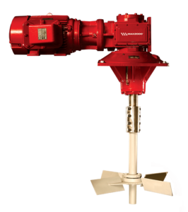
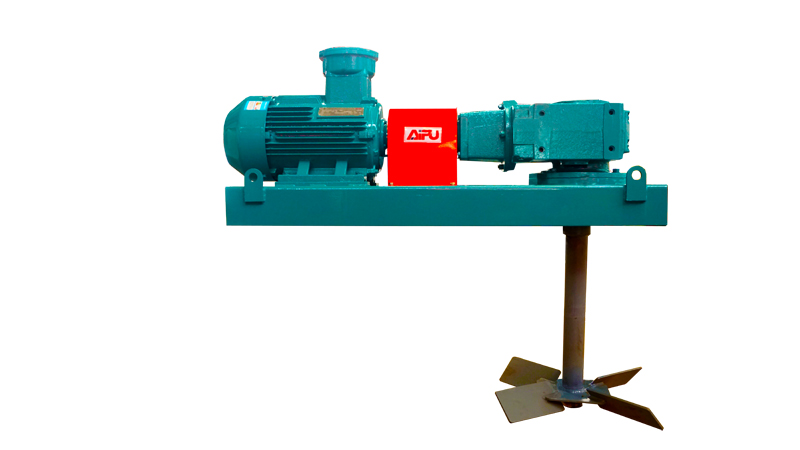
The skid mounted MA-RG agitator is compact, and its low profile reduces headroom requirements and provides more layout space on top of the tanks. The gearbox is a triple-reduction helical-bevel gear drive system that reduces the rotational speed of the motor to drive the impeller(s). Up to 95% mechanical efficiency helps reduce horsepower requirements.
Impellers are available with flat blades (radial flow), contour blades (axial flow), and canted blades (radial/axial flow). The impellers are sized according to tank volume and expected duty. Active mud system compartments—such as solids removal sections, mud mixing sections, and slug pits, which need a higher shear force to produce immediate mixing—are another consideration in impeller sizing.

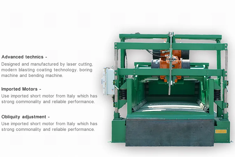
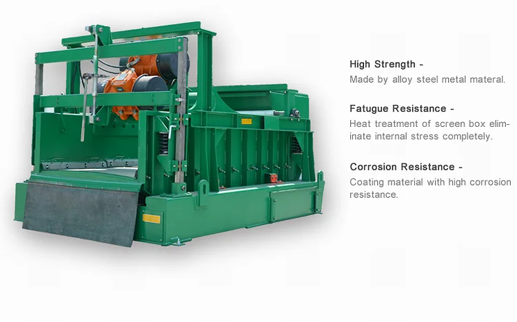
Shale Shaker is the first phrase of solid control systemin drilling fluids processing system, also known as key solids control equipment in drilling mud system, shale shaker decides performance of the whole solids control system. OilMan Solids Control can design double shakers and triplicate shakers on single skid according to clients’special requirements and also supply relevant connecting manifold, according to current industry situation.
Improve your health or your customers’ well-being with the marvelous collection of nov brandt available at unparalleled offers on Alibaba.com. The nov brandt contain rewarding active ingredients that alleviate various health and cosmetic problems. The broad collection of nov brandt ensures that you will find all products of your choice, whether you’re acquiring them for yourself, your family, your friend, or to resell for business purposes.
The nov brandt are obtained from suitable sources including plants and scientific synthesis. Their valuable health effects have been studied and scientific proof supports these benefits. These nov brandt are obtained through highly regulated and controlled production processes to guarantee safety, along with optimal benefits. On Alibaba.com, nov brandt vendors are made of certified manufacturers, suppliers, and wholesalers to ascertain the high quality and compliance with regulatory guidelines.
These nov brandt come in all varieties, considering a range of factors and requirements between individuals and groups of users. When exploring the site, you’ll realize that the nov brandt come in the appropriate dosage forms to suit adults and children"s needs alike. This variability guarantees you that you’ll always find nov brandt that apply to your needs. Additionally, they come with user instructions as well as usage and storage directions to maintain optimal outcomes.
Alibaba.com is the ideal place for you to shop for quality products while saving money. Explore the wide category of nov brandt available on the site and choose the perfect match for you. No matter what your needs are, you will find the most suitable nov brandt to meet your expectations in a convenient manner. Shop today on the site and realize quality is affordable.

As wells have grown more complex in North American shale plays, challenging wellbore conditions, increasingly complicated lithologies and faster drilling have made it necessary to advance shale shaker technology. Shakers must be designed to maximize solids removal and thereby ensure the consistency and reliable operation and performance of the drilling fluid. This results in a fluid that requires less costly dilution to optimize both drilling performance and wellbore condition. National Oilwell Varco (NOV) developed the Brandt SABRE modular shale shaker to provide the industry with improved shaker performance and reliability.
fitted. On this test, screens ranged from API 140 mesh through API 230 mesh during the 8½-in. oil based mud sections, and the ROP averaged 18.2 m/hr to 33.5 m/ hr (60 ft/hr to 110 ft/hr). SABRE consistently discharged significantly dryer cuttings compared to the high-performance single-deck shakers, with retention of oil on cuttings (ROC) averaging 8.85% compared with 11.2%. This was achieved while consistently maintaining low-gravity solids levels below 11.8% with only one SABRE shaker. There was also no requirement to run any other solids control equipment (such as centrifuges) with no increase in the additional dilution typically seen on previous comparable wells. The reduction
In addition, since one shaker was frequently offline, screen inspections and changes could be made very easily. Throughout the program only 91 screens were used in total, which consisted of 24 SABRE screens and 67 screens for the other shaker type. This was significantly less that that seen on the five previous wells drilled with the same rig, where 250 screens had been used. The company man, mud engineers, toolpusher and rig crew all approved of the new system and verified its improved performance over their existing options, with savings of approximately $192,000 during the five-well campaign. With a complete SABRE shaker system (rather than the single test unit), these cost savings and overall benefits would have been significantly greater.
Shale operators drilling across North America and elsewhere will continue to focus on reducing costs and increasing efficiencies for the foreseeable future, particularly as markets remain volatile and shareholders call for greater capital discipline. These needs are driving improvements in solids control, with shale shakers being a primary driver in maintaining the effectiveness and the desired properties of the drilling fluids and thus holding significant value. The more capable a shale shaker, the greater the efficiencies and potential production of the wells. With Brandt SABRE, NOV has brought together design ingenuity, lower total cost of ownership and improved reliability in a modular, flexible system.

GN Solids Control is the first API Certified Company for manufacturing shale shaker screens and solids control equipment from China. GN make replacement shale shaker screens for NOV Brandt shaker and mud cleaners.
GN Shaker Screen is an important division for GN Solids Control to provide high quality & cost effective GN OEM shaker screens, and replacement NOV Brandt shaker screens.
Improve your health or your customers’ well-being with the marvelous collection of nov brandt available at unparalleled offers on Alibaba.com. The nov brandt contain rewarding active ingredients that alleviate various health and cosmetic problems. The broad collection of nov brandt ensures that you will find all products of your choice, whether you’re acquiring them for yourself, your family, your friend, or to resell for business purposes.
The nov brandt are obtained from suitable sources including plants and scientific synthesis. Their valuable health effects have been studied and scientific proof supports these benefits. These nov brandt are obtained through highly regulated and controlled production processes to guarantee safety, along with optimal benefits. On Alibaba.com, nov brandt vendors are made of certified manufacturers, suppliers, and wholesalers to ascertain the high quality and compliance with regulatory guidelines.
These nov brandt come in all varieties, considering a range of factors and requirements between individuals and groups of users. When exploring the site, you’ll realize that the nov brandt come in the appropriate dosage forms to suit adults and children"s needs alike. This variability guarantees you that you’ll always find nov brandt that apply to your needs. Additionally, they come with user instructions as well as usage and storage directions to maintain optimal outcomes.
Alibaba.com is the ideal place for you to shop for quality products while saving money. Explore the wide category of nov brandt available on the site and choose the perfect match for you. No matter what your needs are, you will find the most suitable nov brandt to meet your expectations in a convenient manner. Shop today on the site and realize quality is affordable.

Shale Shaker is the first phrase of solid control systemin drilling fluids processing system, also known as key solids control equipment in drilling mud system, shale shaker decides performance of the whole solids control system. OilMan Solids Control can design double shakers and triplicate shakers on single skid according to clients’special requirements and also supply relevant connecting manifold, according to current industry situation.

requirements and provides more layout space on top of mud tanks. The triple reduction helicalbevel gear drive system reduces the rotational speed of the motor to drive the impeller(s). Up to
This document contains proprietary and confidential information which belongs to National-Oilwell Varco, L.P., its affiliates or subsidiaries (all collectively referred to hereinafter as "NOV"). It is loaned for limited purposes only and remains the property of NOV. Reproduction, in whole or in part, or use of this design or distribution of this information to others is not permitted without the express written consent of NOV. This document is to be returned to NOV upon request and in any event upon completion of the use for which it was loaned. This document and the information contained and represented herein is the copyrighted property of NOV. © National Oilwell Varco
Please take a few minutes to let us know your level of satisfaction with the NOV Brandt® equipment you have recently purchased. Your comments will help identify potential areas of improvement. Please send this completed form to: NOV Attn.: Global Marketing 2800 N. Frazier St. Conroe, TX 77303 Phone: 936-523-2600 Fax: 936-788-7367 E-mail: [email protected] See Chapter 8, titled "Worldwide Locations" for your nearest representative.
Chapter 3: Installation Installation . . . . . . . . . . . . . . . . . . . . . . . . . . . . . . . . . . . . . . . . . . . . . . . . . . . . . . . . . . . . . Agitator Safety Flow Diagram. . . . . . . . . . . . . . . . . . . . . . . . . . . . . . . . . . . . . . . . . . . . . Familiarise with GA"s and Scope of Work . . . . . . . . . . . . . . . . . . . . . . . . . . . . . . . . . . . Review the Installation Manual. . . . . . . . . . . . . . . . . . . . . . . . . . . . . . . . . . . . . . . . . . . . Identify the Crates and Review the Packing List . . . . . . . . . . . . . . . . . . . . . . . . . . . . . . Handling . . . . . . . . . . . . . . . . . . . . . . . . . . . . . . . . . . . . . . . . . . . . . . . . . . . . . . . . . . . . . Planning Meeting . . . . . . . . . . . . . . . . . . . . . . . . . . . . . . . . . . . . . . . . . . . . . . . . . . . Risk Assessment . . . . . . . . . . . . . . . . . . . . . . . . . . . . . . . . . . . . . . . . . . . . . . . . . . . To Site . . . . . . . . . . . . . . . . . . . . . . . . . . . . . . . . . . . . . . . . . . . . . . . . . . . . . . . . . . . Unpack . . . . . . . . . . . . . . . . . . . . . . . . . . . . . . . . . . . . . . . . . . . . . . . . . . . . . . . . . . . . . . Component Check . . . . . . . . . . . . . . . . . . . . . . . . . . . . . . . . . . . . . . . . . . . . . . . . . . . . . Inform NOV . . . . . . . . . . . . . . . . . . . . . . . . . . . . . . . . . . . . . . . . . . . . . . . . . . . . . . . . . . Installation - Planning Meeting . . . . . . . . . . . . . . . . . . . . . . . . . . . . . . . . . . . . . . . . . . . .
General Information This manual contains installation, operation, maintenance and parts information. Information in this manual should enable qualified personnel to install, operate and troubleshoot this system. Every effort has been made to ensure the accuracy of the information contained herein. NOV will not be held liable for errors in this material, or for consequences arising from misuse of this material.
Warranty NOV warrants that, for a period of one year from the date of delivery equipment of manufacture, the Equipment shall be free of defects in materials and workmanship under normal use and service, and provided the Equipment is used and maintained in accordance with instructions supplied. This is the sole and exclusive warranty. If a defect in the Equipment appears within one year from the date of shipment, and Purchaser has given written notice of such defect within thirty days from the discovery thereof, we will repair or replace the part, at our option, by shipping a similar part FOB shipping point or, at our option, refund an equitable portion of the purchase price. We may require the return, to a designated location, of the defective part, transportation prepaid to establish Purchaser"s claim. No allowance will be made for repairs undertaken without our written consent or approval. This warranty applies only to equipment manufactured by NOV Brandt®. Warranties on equipment manufactured by others, if any, are assigned to Purchaser (without recourse) at time of delivery. Any description of Equipment, drawings, specifications, and any samples, models, bulletins, or similar material, used in connection with this sale are for the sole purpose of identifying the Equipment and are not to be construed as an express warranty that the Equipment will conform to such description. Any field advisory or installation support is advisory only. The foregoing warranties are in lieu of all other warranties, whether oral, written, express, implied or statutory. Implied warranties or merchantability and fitness for a particular purpose will not apply. Our warranty obligations and purchaser"s remedies thereunder are solely and exclusively as stated herein. Purchaser"s sole and exclusive remedy, whether based upon warranty, contract or tort, including negligence, will be to proceed under this warranty. All liability shall terminate one year from the date of delivery of the Equipment.
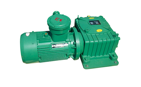
Product Information Introduction Brandt® MA-RG Series Agitators are heavy-duty mechanical mixers for viscous fluids. The gearbox is a helical-bevel gear drive system that reduces the rotational speed of the motor to drive the impeller(s). The impeller shaft is suspended from and attached to the output shaft of the gearbox. Several models are available to meet a variety of mixing needs. The naming convention for these models is: MA-XRG where X = the horsepower of the unit and RG indicates the helical-bevel gearbox. For example, MA-20RG is the 20 hp mud agitator with a helical-bevel gearbox. MA-RG Series Agitators are very compact. Their low profile reduces headroom requirements and provides more layout space on top of the tanks. The 1:1 height-to-width ratio results in a lower center of gravity, providing stability and safety should the impeller encounter a sudden shock load. MA-RG Series Agitators use a mounting skid. An even lower profile version of the MA-RG Series Agitator is offered in which a base plate is used instead of the mounting skid to reduce the overall height. The naming convention for the agitator with a base plate is: MA-XRGLP Another variation of the MA-RG Series Agitators has a C-face motor with a close coupling style. This variation also has a base plate instead of a mounting skid and naming convention is: MA-XRGC For example, the MA-3RGC is the 3 hp mud agitator with a helical-bevel gearbox, a base plate and a C-face motor. Each MA-RG Agitator uses a shaft-mounted impeller to maintain a homogeneous mixture of liquids and solids within a tank. Impellers are available with flat blades (radial flow), contour blades (axial flow), and canted blades (radial/axial flow). Blades may be installed in single or multiple configurations to provide the desired results. There are several options available for MA-RG Series Agitators. Popular options include special paint finishes, remote starters, other electrical controls, and special duty motors. Contact your sales representative to discuss which options may be right for your application. See Chapter 8, titled "Worldwide Locations" to locate the office nearest you.
Unit Description Each MA-RG Agitator consists of a motor, gearbox, mounting base and shaft-mounted impeller. Electrical controls, special coatings, custom bases, and other options are available.
Motor The motors used on the mud agitators are explosion proof, three-phase electric motors directly coupled to the gearbox using a flexible coupling with a solid steel guard. Motors are available for most voltage/frequency requirements. Other electrical code styles and temperature ratings are also available.
Gearbox The gearbox is a triple-reduction helical-bevel gear drive reducing the motor speed (1800 rpm @ 60 Hz / 1500 rpm @ 50 Hz) to the agitator speed (60 rpm / 50 rpm respectively) in a 30:1 nominal reduction. The actual output speed varies by motor and gearbox size. The gearbox contains an output shaft, two seals, and four to six bearings in addition to the helicalbevel gear system. The bearings are generously spaced to minimize shaft vibration and deflection. Seals are standard sizes readily obtainable.
Contour-blade Impellers On contour blade impellers (see Figure 2-3), the blades are designed with a variable pitch reducing the horsepower requirements and inducing less shear to the mud. Contour blades move liquid downward to the bottom of the tank, along the tank bottom toward the tank walls and then up the tank wall. All fluid in the tank is mixed continuously and the same consistency is maintained in all parts of the tank. Field experience has confirmed that this design provides the most homogeneous mixture in the widest range of installations. Complete fluid agitation minimizes fluid control problems caused by inconsistent mixtures. Contour blades also use less horsepower than canted blades.
Multiple Impellers When an agitator is used in an extremely deep tank, over 15 feet (4.5 m) deep, multiple impellers can be mounted on one shaft. Usually the upper impeller(s) is a canted or contour blade and the bottom impeller is a flat blade. A bottom shaft stabilizer is often required for multiple impellers. Contact our engineering department for proper impeller sizing and stabilizer requirements. See Chapter 8, titled "Worldwide Locations" to locate the office nearest you.
Impeller Shaft Standard impeller shafts for MA-RG Series Agitators are manufactured of solid mild steel. The impeller shaft is coupled to the gearbox with a rigid coupling. All shafts are keyed to adjust the height of the impeller. Shaft length is determined by tank depth. When ordering impeller shafts, always specify the actual tank depth. Tank depth is defined as the distance from the bottom of the tank to where the agitator is mounted.
Bottom Shaft Stabilizer A bottom shaft stabilizer is required in deep tanks to reduce side loading on the gearbox bearings. The stabilizer also protects the agitator shaft and impeller when auxiliary equipment is carried inside the mud tank during rig moves. Bottom shaft stabilizers are required when the tank depth is 8 feet (2.4 m) or more. 12 www.nov.com/brandt
Available Models MA-RG Series Agitators are available in several models from 3 to 40 hp. The following table lists the physical specifications for each agitator model.
Installation Installation Proper installation of the agitator will help ensure proper operation with low level of vibration and long service life. Installation should start at the top with connections then made toward the bottom. Before installing the shafts, all coupling connections must be cleaned of all debris, sand or rust. All connections must be torqued to the manufacturer’s specifications. Do not use grease or anti-seize compound between the connections.
Agitator Safety Flow Diagram The list below illustrates the safe and ideal steps in which to install the agitator. It is therefore recommended that these steps are followed in order that a safe and efficient installation of the equipment will take place.
Familiarise with GA"s and Scope of Work The general arrangement drawings supplied are to be reviewed to assist in the location and orientation of the agitators. All personnel involved in the installation should make themselves aware of the complete scope of the work.
Review the Installation Manual The installers should familiarize themselves and follow the installation procedures contained in this manual. Any issues or questions regarding installation, commissioning or use of the agitators can be addressed by the field service representative.
Identify the Crates and Review the Packing List With the aid of the packing list, each agitator and shaft can be identified readily by the markings on each crate. All crate gross weights are on the crate labels and packing lists.
Handling Planning Meeting For handling the agitator and shaft crates to the site, personnel involved should attend the Planning Meeting to decide on the safest, most direct route to move the agitator and shaft crates into position as close as possible to the final location.
Risk Assessment Risk assess any potential hazard that may lead to serious injury or death when transporting the agitator and shaft crates. Hazards must then be addressed by all key personnel to ensure safe transit of the crates to the site location.
To Site Extreme care must be taken to prevent damage when moving the agitator and shaft crates. Ideally, the use of a spreader bar with soft fabric slings is the recommended support method for lifting. Never lift a crate with only one support point. Only certified sling sets are to be used. Ideally, soft fabric slings should be used to minimise damage to the crates or components. All lifting equipment and procedures must comply with applicable safety requlations.
Unpack Personnel should always unpack the agitator and shaft in an efficient and safe manner providing a clean and safe working environment. The equipment will be delivered to the site in crates. Remove any protective sheeting and steel banding used to secure the crates. Remove the lid and then the sides, taking particular care not to damage the equipment or cause injury to any personnel. Any small loose items should remain in the crates awaiting storage or installation.
Component Check All components enclosed in the agitator and shaft crates are to be thoroughly checked against the packing list to ensure all items have been delivered/received.
Installation - Planning Meeting Planning meeting is to be carried out prior to installation of the agitators and shafts. A clear plan of action is to be deduced involving key personnel on how best to install the agitators and shafts efficiently and safely.
Installation - Risk Assessment All potential hazards that may lead to serious injury or death during the installation process must be taken into account. Hazards must then be addressed by all key personnel to ensure a safe and efficient installation of the agitators and shafts.
Support Structure Adequate support must be made in the deck in order to support the agitator correctly. Suitable structure should be designed based on reaction forces specified on the installation drawings (if applicable included in documentation package) and/or in this manual. The following information should be reviewed and taken into consideration:
Agitator weight and design loads (Refer to table titled "MA-RG Series Models" on page 11 for weights of agitators and table titled "Impeller Shaft Measurements" on page 10 for shaft weights and maximum torque.)
Placement of structural members to allow full contact support for the agitator skid footprint Use of structural members of equal or higher rigidity to the material used in the agitator skid is recommended. Typically I-beams of respective strength in the lateral and horizontal bulk head to bulk head cross sections is sufficient to support the base/skid of the agitator.
Placement of the agitator Directly to the tank deck is recommended. Lowering the mounting height improves the strength of the structure and lowers the center of gravity, improving resistance to vibration.
The agitator frame should be supported by a rigid structure making the first fundamental natural frequency of the whole system 15 % above the operating rotating frequency of the motor and having following characteristics:
The agitator skid has been engineered to have the first natural frequency 50 % or more above the motor operating speed. The natural frequency of the combined rigid structures is different than that of its components as well as dependent on the rigidity of their connection. Verification of the natural frequency of an as-installed structure might be helpful in eliminating any resonance. Should resonance of the combined structure occur, it can be eliminated by modification of either the supporting structure or the rigidity of agitator skid to support structure connection. The system natural frequency is typically directly proportionate to its stiffness. Increasing stiffness will shift the natural frequency up, thus decreasing the possibility of resonance. This can be achieved by: 1. use of rigid, symmetrical and leveled structural support for the agitator base. 2. adding cross members to the support structure. 3. minimizing the gaps between the agitator base and the support structure or closing of the gaps by welding. Minimize the use of shims. 4. minimizing agitator shaft misalignment.
Below is an example of an installation where adequate primary structural support was added to strengthen the deck area in which the agitators were installed.
Please note that sub support frames for the agitator baseplates must be suitably fabricated. Inadequately fabricated support frames can cause instability or vibration issues.
Lifting and Mounting Lifting should be performed with proper lifting equipment and using only the designated agitator lifting points. The agitator should be stored and lifted with its shipping crate until it is ready to be installed in its final destination. The agitator should never be rested on the gearbox output shaft. Once the agitator is in its intended position, check the alignment of the mounting holes and gaps between the agitator skid and support structure as follows:
The gap between the agitator skid and support structure at the bolting points before bolt down should be less than 0.025 in. (0.635 mm). Gaps at the bolting points ranging from 0.025 in. (0.635 mm) to 0.5 in. (12.7 mm) should be eliminated using shims to prevent deflection of the agitator skid and impact on shaft alignment.
If needed, the agitator skid can be permanently welded to the supporting structure to close excessive gaps between the structures. Alternatively, the support frame can be build and fitted to the agitator skid before being welded to the tank deck. Any gaps resulting from unevenness of the tank structure can be closed while welding the support frame. Ensure that the skid is grounded before welding. Failure to do so can result in electrical system damage.
Installation All MA-RG Agitators are supplied as shop assembled agitators. All shaft assemblies are broken down into various separate parts (shaft complete with coupling/bushing assembly, impeller assembly and stabilizer housing) to aid in maneuvering parts into mud pits with restricted access. Two type of shafts are manufactured; either a solid shaft that is keyed for the impeller or a pipe spool to which the impeller is bolted. The solid shaft installation instructions are given followed by the pipe spool installation instruction on page 31.
Mechanical Installation 1. Refer to the "Taper-Lock Coupling Installation Instructions" that is supplied in the "Supporting Documents". These should be reviewed to familiarise the user with the shaft fixing components being used. 2. Before locating the agitator on top of the tank, ensure the surface is square and level. 3. Ensure before installation of the agitator onto the top of the tank, the structure is strong enough to hold the unit and the tank dimensions are correct as per the general arrangement drawings. It is recommended the agitators are bolted to rigid beams. 4. The agitator assembly can be lifted to its location and into place using the four lifting eyes provided on the unit and a correct four leg lifting sling assembly (not supplied). The agitator assembly should be placed on blocks in the exact location it will be secured to give 19.685 in. (500 mm) clearance from the bottom of the tank to the bottom of the shaft assembly when the shaft assembly is fitted to the agitator assembly. This is to ensure the stabilizer will be fitted in the correct location. The agitator assembly and shaft assembly need to be fitted before the stabilizer to ensure correct alignment.
5. Ensure access into the tanks is large enough for the shaft assemblies, impeller assemblies and stabilizers. If it is possible to assemble the shafts completely before positioning inside the tank, skip to step 8. 6. The impeller assemblies can be reduced in diameter by removing the blades, up to 4 if necessary. 42 www.nov.com/brandt
7. If the blades have been removed from the impellers, they need to be reinstalled. Refer to the section titled "Bolt Torque Requirements" on page 102 for the correct torque for the agitator fasteners. 8. When assembling the shafts, it is advisable to use two trestles and set the shaft in between them for ease of assembly. See Figure 3-8.
10. Install the impeller the correct way up. The impeller blades should be oriented so that the fluid is pushed downward when the agitator is rotating clockwise when viewed from the top, i.e. the leading edge of the paddle will be in the higher position with the trailing edge in the lower position. 11. Ensure the bushing key is in the shaft keyway. Slide the impeller onto the shaft past the key. Slide on bushing over the keyway and locate with the impeller coupling. 12. Locate the key and slide the impeller so that when the impeller is installed, the distance from the bottom of the impeller blades to the tank bottom is roughly 0.75 times the impeller diameter. For example, if the impeller diameter is 36 in. (914.4 mm), then the distance from the bottom of the impeller blade to the tank bottom should be 27 in. (685.8 mm). If installing dual shafts, the top shaft impeller distance should be taken from the bottom of the top shaft coupling connection to the bottom of the impeller blade.
26. If the shaft has been assembled outside of the tank then, using the appropriate slinging arrangement, lower the shaft through deck cut out on top of the tank. If required, the shaft can be temporarily tied on the side of the tank. When the agitator is fitted with dual shafts, the lower shaft should be put in the tank first.
27. If the shafts are to be stored after assembly on site, preservation fluid must be applied to shafts and couplings. 28. The shaft should now be assembled to the rigid coupling under the agitator gearbox as per Figure 3-17. This half coupling is fixed at the factory and under no circumstances should be removed by the user without consulting with a field service representative. 29. The stabilizer housing should never be permanently installed to the tank floor until the agitator and the shaft are installed, properly aligned and bolted down. Failure to follow this step may result in the shaft falling out of the rigid coupling/bushing. 30. Before installing the stabilizer, make sure the tank floor is suitable to weld the stabilizer. If not, weld a doubler plate on the tank floor directly underneath the shaft. 31. To install, slide the stabilizer over the bottom of the agitator shaft once the impeller has been installed but before the agitator is bolted down. 32. The blocks should be removed and the agitator should be secured to the mud tank using the mount hole pattern shown on the installation drawing, or the unit can be directly welded to the mud tank (provided necessary risk assessments are agreed and approved). www.nov.com/brandt
See the section titled "Bolt Torque Requirements" on page 102 for the correct torque of the agitator fasteners. The shaft alignment should then be checked by rotating the impeller through several revolutions manually.
33. Once the agitator shaft is properly aligned, the stabilizer should be positioned so that the shaft is centered within the stabilizer. 34. In the case of sloping tank bottoms, cut the stabilizer to suit the tank profile. 35. Profiling the stabilizer to suit might result in losing the drain holes on the stabilizer bottom. If so, similar drain holes must be made on to the stabilizer before welding onto the tank. See Figure 3-18.
If correct position of the stabilizer location cannot be achieved: a. Check the agitator shaft runout. Make sure all connections are flush with no gaps between the two surfaces. b. Check for level mounting of the skid base. c.
d. It may be required to reinstall the shaft ensuring that all connecting surfaces are clean, making good contact and properly torqued. If water will be used in the tank during start up, the shaft stabilizer should be lubricated with grease to reduce friction and minimize vibration during start up. Operation with mud does not require lubrication. 40. Only after these steps are completed and assured that the shaft is centered within the stabilizer should the stabilizer be permanently secured to the tank floor by means of welding. 41. The shaft should locate into the stabilizer at 50 % of the total height. 75 % is the maximum and 40 % is the minimum. 42. Check the impeller height and adjust if necessary. Reference step 12 for the correct height.
Pipe Spool Installation 1. Before locating the agitator on top of the tank, ensure the mounting surface is square and level. 2. Ensure the support structure is adequately designed to hold the unit and the tank dimensions are correct as per the general arrangement drawings. It is recommended for the agitators to be bolted or welded to rigid beams. 3. Ensure access into the tanks is large enough for the shaft assemblies, impeller assemblies and stabilizers. 4. Place the skid on the foundation and ensure level of the unit. Level check should be performed on skid main beams as well as on the gearbox housing in both directions. Proper shimming is required. See the section titled "Lifting and Mounting" on page 17. 5. After shimming, bolt or weld the unit to the foundation. Ensure that skid is grounded before welding. Failure to do so can result in electrical system damage. 6. Clean all debris, grease and other contaminants from the coupling faces. 7. Bolt the first pipe spool to the gearbox coupling. Torque the bolts to 40 % of the recommended torque. Torque the bolts in a series of diagonally opposite pairs. Tighten each a little at a time up to 40 % of the recommended torque. 8. Check the runout along the pipe spool to observe the trend. See Figure 3-22. Rotate the shaft by hand. Mark the high and low runout points on the bottom of the pipe by the coupling weld. Note runout values. See Figure 3-23. 9. Check the runout on the bottom face. See Figure 3-23. Mark the high and low values. 10. Unbolt the first pipe spool. Rotate the shaft 180° and repeat steps step 7 - 9. See Figure 324. 11. Compare the two runouts and select the lower value for the next installation step.
13. Check once more the runout on the coupling face. Starting with the smaller runout side, torque the bolts in a series of diagonally opposite pairs to 100 % of the recommended torque. Refer to the section titled "Bolt Torque Requirements" on page 102 for the correct torque values for the agitator fasteners. 14. Prepare the impeller hub and the second pipe spool section. Clean all faces. 15. Position the impeller hub the correct way. See Figure 3-25. The impeller hub blades should be oriented so that the fluid is pushed downward when the agitator is rotating clockwise when viewed from the top; i.e. the leading edge of the blade will be in the higher position with the trailing edge in the lower position. 16. Bolt the second pipe spool to the first pipe spool with impeller hub between the two coupling faces. Torque the bolts to 40 % of recommended value. Torque the bolts in a series of diagonally opposite pairs. Tighten each a little at a time. 17. Check the runout along the second pipe spool to observe the trend. Mark the high and low runout points on the bottom of the pipe by the coupling weld. 18. If the runout is adding to the runout of the first pipe spool, rotation of the second pipe is necessary. Using the markings on the first pipe spool, unbolt the second pipe spool, rotate it 180° and re-bolt it once more to 40 % of the recommended torque. 19. Check the runout once more.
20. Torque the bolts to the recommended value. Refer to the section titled "Bolt Torque Requirements" on page 102 for the correct torque values for the agitator fasteners. Torque the bolts in a series of diagonally opposite pairs. Tighten each a little at a time. 21. For agitators with multiple impellers, repeat step 14 - 20. 22. Prepare the bottom shaft stabilizer and stub shaft or pipe stub shaft (for pipe spools longer than 35 ft [10.7 m]) for installation by cleaning all faces. Place the stabilizer and stub shaft together underneath the hanging pipe spool. See Figure 3-26. 23. Bolt the stub shaft to the pipe spool. Torque the bolts to the recommended value. Refer to the section titled "Bolt Torque Requirements" on page 102 for the correct torque for the agitator fasteners. Torque the bolts in a series of diagonally opposite pairs. Tighten each a little at a time. 24. Before installing the stabilizer, the following checks should be performed: a. Ensure the tank floor is suitable to which to weld the stabilizer. b. Ensure the gearbox and skid are level. 25. For pipe spool installation on drill ships or other semi-submersibles, weld the stabilizer in place at the quayside. 26. In the case of sloping tank bottoms, prepare a support structure for the stabilizer. 27. Place the bottom shaft stabilizer in its intended position. 28. Measure the shaft runout at the stabilizer by slowly rotating the shaft.
If correct positioning of the stabilizer cannot be achieved: a. Check the agitator shaft runout. Make sure all connections are flush with no gaps between the two surfaces and there are no shims between the pipe spools. b. Check for level mounting of the skid base. c.
30. Only after these steps are completed and it is assured that the shaft is centered within the stabilizer should the stabilizer be permanently welding to the tank floor. Ensure the skid is grounded before welding. Failure to do so can result in electrical system damage. 31. Install the impeller blades. The impeller blades should be oriented so that the fluid is pushed downward when the agitator is rotating clockwise when viewed from the top, i.e. the leading edge of the blade will be in the higher position with the trailing edge in the lower position. See Figure 3-28.
32. If water will be used in the tank during commissioning, the stabilizer should be lubricated with grease to reduce friction and minimize vibration during start up. See Figure 3-29. Operation with mud does not require lubrication.
Gearbox and Motor Shaft Alignment The agitators are aligned at the factory before performance of the Factory Acceptance Test. The alignment between the shafts should be inspected after installation of the agitator to ensure that transportation, handling or installation has not caused a misalignment. Poor alignment can result in increased vibration and failure or decreased service life of the coupling, gearbox or motor bearings. Alignment should not be attempted until the base is in position and the mounting and flange bolts have been tightened.
START / STOP Station This unit is supplied by others and is out of the scope of supply. The unit should be certified for the Zone 1 and should have as high an ingress protection rating as possible (minimum of IP56). The remote START/STOP station should be sited within an area such that the operator can ensure that no exposed persons are in the danger zone around the agitator before operating.
Emergency Stop Station This unit is supplied by others and is out of the scope of supply. The unit should be certified Zone 1 and have an ingress rating of IP56 minimum. The unit must be positioned for easy access and for non-hazardous operation by the operator or others who may need to use it. Measures against inadvertent operation should not impair accessibility. The unit should be mounted not less than 2 feet (0.6 m) above the servicing level. Ideal height is 5.5 feet (1.7 m). The ideal position is such that you can see the whole agitator but do not need to go into the danger area to operate it. Other accessible locations can be considered, i.e. close to doorways, exits, etc. The emergency stop should not be used as a functional stop for the unit but should be tested on a regular basis to ensure reliable switching. Weekly testing is recommended. Use properly certified seal glands.
General Electrical Cabling / Distribution Ensure each electric motor has a same voltage and frequency with the accepted tolerance limits voltage +/- 5 %, frequency +/- 2 % of the rig supply voltage. Cables will be run in accordance with the single line block diagram. Great care must be taken when wiring to the electric motors. Only use recommended cable (as per the drawings) or its equivalent. Cables to the electric motors must be externally supported. Cable trays should be installed in conjunction with the appropriate vessel installation / assembly drawings. Ensure the cable is free to move (without excessive movement) prior to the terminal box cable entry. Ensure the cable has sufficient length so as not to be strained during operation preferably by means of a loop or "pig-tail". Do not leave the electrical wires inside the terminal box too long. Always use ring type crimps when attaching the electrical wires to the motor terminals. Use properly certified seal glands. Unused cable entries must be plugged with appropriate certified plugs. 42 www.nov.com/brandt
After obtaining the correct permit for connecting electrical power, check rotation for the correct direction. Incorrect rotation can result in serious damage to the agitator and related gearbox. If necessary, reconnect the electrical leads to reverse the rotation of the agitator motor.
Grounding All agitators and motors must be grounded to the supporting structure. For details of proper grounding, refer to the client"s documentation.
Long Term Storage Store the MA-RG Agitator in a cool, dry place. The MA-RG Agitator is packaged to prevent corrosion for a period of 12 months if stored indoors. During shipping, all openings are covered or capped to protect the inside from dust, rust and moisture. Threaded connections, couplings and shafts are coated with a corrosion inhibitor. If the equipment is to be subjected to prolonged shutdown or storage, take the following steps to ensure that the unit does not degrade during storage:
If water is used in the tank, the shaft stabilizer should be lubricated with grease to reduce friction and minimize vibration during start up. Operation with mud does not require lubrication.
Oil should be within 1/2 in. (12 mm) of the bottom of the oil level hole as shown in Figure 4-1. Do not overfill. Always check the oil level with the MA-RG Agitator off.
Changing the Gearbox Oil Verify the location of the oil drain plug, the breather plug and the oil level plug for your MA-RG Series Agitator model in Figure 6-1. 1. Turn the unit off. 2. LOCKOUT/TAGOUT the power supply to the agitator. Allow the gearbox to cool or open the vent plug before opening the level plug. Hot oil may escape rapidly and cause burns. 3. Remove the oil drain plug. 4. Drain the used oil into a suitable container and replace the oil drain plug. 5. Remove the fill/level plug. 6. Fill the gearbox with the correct amount of acceptable oil. The gear reducer is properly filled when oil just begins to flow out of the oil level hole. 7. Replace the fill/level plug. Gear oil is extremely slippery and sticky. Gear reducers are most easily filled using a pump or pressurized lubrication gun. Be sure to dispose of used oil properly and clean area of any spilled oil after completing this procedure.
Routine Maintenance Checklist The MA-RG Series Agitator is designed for years of dependable service with routine inspection and maintenance. Additional copies of this checklist should be placed close to the unit for quick reference.
Startup 1. Check the oil level with the agitator turned off. The oil should be within 1/2 in. (12 mm) of the bottom of the oil level hole. Do not overfill.
2. The impeller should rotate clockwise when viewed from top. 3. The oil fill/breather plug must be clear of any obstruction to prevent pressure build-up and possible seal damage. 4. The agitator should operate with no vibration. 5. Check the rubber insert on the input shaft coupling for wear and cracks. 6. For optimal performance, change the oil after the first five days of operation, particularly if the unit has been in storage.
Daily 1. Check for oil leaks. 2. Keep the motor clean and ventilation openings clear of mud build-up or other debris. 3. Check the impeller shaft coupling for proper make-up.
Parts and Drawings Recommended Spare Parts The following table lists the spare parts recommended for the MA-RG Series Agitator operating for one year under typical conditions. Contact your nearest representative for spare parts for other conditions. Oil is sold in 5 gallon (18.9-liter) units only.
DESCRIPTION COUPLING RIGID FEMALE BUSHING SHAFT SHAFT BUSHING IMPELLER STABILIZER IMPELLER IMPELLER 20 DIA CANTED IMPELLER 24 DIA CANTED IMPELLER 28 DIA CANTED IMPELLER 30 DIA CANTED IMPELLER 32 DIA CANTED IMPELLER 20 DIA FLAT IMPELLER 24 DIA FLAT IMPELLER 28 DIA FLAT IMPELLER 20 DIA CONTOUR IMPELLER 24 DIA CONTOUR IMPELLER 28 DIA CONTOUR IMPELLER 32 DIA CONTOUR IMPELLER 34 DIA CONTOUR IMPELLER 42 DIA CONTOUR AGITATOR S & I CHECKLIST KEY3/8" x 3/8" x 1 3/4" KEY3/8" x 3/8" x 1 1/4"
DESCRIPTION COUPLING RIGID FEMALE BUSHING SHAFT SHAFT BUSHING IMPELLER STABILIZER IMPELLER IMPELLER 20 DIA CANTED IMPELLER 24 DIA CANTED IMPELLER 28 DIA CANTED IMPELLER 30 DIA CANTED IMPELLER 32 DIA CANTED IMPELLER 34 DIA CANTED IMPELLER 36 DIA CANTED IMPELLER 20 DIA FLAT IMPELLER 24 DIA FLAT IMPELLER 28 DIA FLAT IMPELLER 30 DIA FLAT IMPELLER 32 DIA FLAT IMPELLER 36 DIA FLAT IMPELLER 28 DIA CONTOUR IMPELLER 32 DIA CONTOUR IMPELLER 34 DIA CONTOUR IMPELLER 36 DIA CONTOUR IMPELLER 38 DIA CONTOUR IMPELLER 42 DIA CONTOUR AGITATOR S & I CHECKLIST
DESCRIPTION COUPLING RIGID FEMALE BUSHING SHAFT SHAFT BUSHING IMPELLER STABILIZER IMPELLER IMPELLER 20 DIA CANTED IMPELLER 24 DIA CANTED IMPELLER 28 DIA CANTED IMPELLER 30 DIA CANTED IMPELLER 30 DIA CANTED IMPELLER 32 DIA CANTED IMPELLER 36 DIA CANTED IMPELLER 38 DIA CANTED IMPELLER 20 DIA FLAT IMPELLER 24 DIA FLAT IMPELLER 28 DIA FLAT IMPELLER 30 DIA FLAT IMPELLER 30 DIA FLAT IMPELLER 32 DIA FLAT IMPELLER 36 DIA FLAT IMPELLER 34 DIA CONTOUR IMPELLER 36 DIA CONTOUR IMPELLER 38 DIA CONTOUR IMPELLER 42 DIA CONTOUR AGITATOR S & I CHECKLIST KEY5/8" x 5/8" x 3"
DESCRIPTION COUPLING RIGID FEMALE BUSHING SHAFT SHAFT BUSHING IMPELLER STABILIZER IMPELLER IMPELLER 24 DIA CANTED IMPELLER 28 DIA CANTED IMPELLER 30 DIA CANTED IMPELLER 32 DIA CANTED IMPELLER 36 DIA CANTED IMPELLER 38 DIA CANTED IMPELLER 40 DIA CANTED IMPELLER 44 DIA CANTED IMPELLER 24 DIA FLAT IMPELLER 28 DIA FLAT IMPELLER 30 DIA FLAT IMPELLER 32 DIA FLAT IMPELLER 36 DIA FLAT IMPELLER 38 DIA FLAT IMPELLER 40 DIA FLAT IMPELLER 44 DIA FLAT IMPELLER 28 DIA CONTOUR IMPELLER 32 DIA CONTOUR IMPELLER 34 DIA CONTOUR IMPELLER 36 DIA CONTOUR IMPELLER 38 DIA CONTOUR IMPELLER 42 DIA CONTOUR IMPELLER 45 DIA CONTOUR IMPELLER 45 DIA CONTOUR IMPELLER 52 DIA CONTOUR AGITATOR S & I CHECKLIST
DESCRIPTION COUPLING RIGID FEMALE BUSHING SHAFT SHAFT BUSHING IMPELLER STABILIZER IMPELLER IMPELLER 30 DIA CANTED IMPELLER 32 DIA CANTED IMPELLER 36 DIA CANTED IMPELLER 38 DIA CANTED IMPELLER 40 DIA CANTED IMPELLER 42 DIA CANTED IMPELLER 44 DIA CANTED IMPELLER 48 DIA CANTED IMPELLER 30 DIA FLAT IMPELLER 32 DIA FLAT IMPELLER 36 DIA FLAT IMPELLER 38 DIA FLAT IMPELLER 40 DIA FLAT IMPELLER 44 DIA FLAT IMPELLER 28 DIA CONTOUR IMPELLER 34 DIA CONTOUR IMPELLER 38 DIA CONTOUR IMPELLER 42 DIA CONTOUR IMPELLER 45 DIA CONTOUR IMPELLER 45 DIA CONTOUR IMPELLER 48 DIA CONTOUR IMPELLER 52 DIA CONTOUR IMPELLER 54 DIA CONTOUR AGITATOR S & I CHECKLIST
DESCRIPTION COUPLING RIGID FEMALE BUSHING SHAFT SHAFT BUSHING IMPELLER STABILIZER IMPELLER IMPELLER 28 DIA CANTED IMPELLER 32 DIA CANTED IMPELLER 36 DIA CANTED IMPELLER 36 DIA CANTED IMPELLER 40 DIA CANTED IMPELLER 40 DIA CANTED IMPELLER 42 DIA CANTED IMPELLER 44 DIA CANTED IMPELLER 46 DIA CANTED IMPELLER 48 DIA CANTED IMPELLER 28 DIA FLAT IMPELLER 32 DIA FLAT IMPELLER 36 DIA FLAT IMPELLER 40 DIA FLAT IMPELLER 44 DIA FLAT IMPELLER 48 DIA FLAT IMPELLER 45 DIA CONTOUR IMPELLER 48 DIA CONTOUR IMPELLER 52 DIA CONTOUR IMPELLER 54 DIA CONTOUR IMPELLER 56 DIA CONTOUR IMPELLER 60 DIA CONTOUR IMPELLER 42 DIA CONTOUR AGITATOR S & I CHECKLIST KEY3/4" x 3/4" x 3 1/2"
DESCRIPTION COUPLING RIGID FEMALE BUSHING SHAFT SHAFT BUSHING IMPELLER STABILIZER IMPELLER IMPELLER 36 DIA CANTED IMPELLER 40 DIA CANTED IMPELLER 42 DIA CANTED IMPELLER 44 DIA CANTED IMPELLER 48 DIA CANTED IMP 48 DIA CANTED WITH BOLT ON PADDLES IMPELLER 52 DIA CANTED IMPELLER 40 DIA FLAT IMPELLER 44 DIA FLAT IMPELLER 48 DIA FLAT IMPELLER 50 DIA FLAT IMPELLER 52 DIA FLAT IMPELLER 48 DIA CONTOUR IMPELLER 52 DIA CONTOUR IMPELLER 54 DIA CONTOUR IMPELLER 56 DIA CONTOUR IMPELLER 60 DIA CONTOUR IMPELLER 64 DIA CONTOUR AGITATOR S & I CHECKLIST KEY7/8" x 7/8" x 4 1/2"
Global Headquarters for Brandt® Product Sales, NOV FluidControl and NOV Portable Power 4310 N. Sam Houston Pkwy East Houston, Texas 77032 United States Phone: 713 482 0500 Fax: 713 482 0690
Global Manufacturing for Brandt® Product Sales, NOV FluidControl and NOV Portable Power 2800 N. Frazier Street Conroe, Texas 77303 United States Phone: 936 523 2600 Fax: 936 788 7367
The VMAI series mud agitators are a vertically mounted motor with ahelical inline gearbox. They are heavy duty mechanical mixers used forviscous fluids such as drilling fluids. The gearbox utilizes a parallel helicalgear drive system that reduces the rotational speed of the motor to drivemounted impeller to maintain a homogeneous mixture of liquids and solidswithin a tank. Impeller are available with flat blades (radial flow), contourblades (axial flow), and canted blades (radial/axial flow). Blades may beinstalled in single or multiple configurations to provide desired results.Multiple sizes and locations of impeller configurations are available. Theseagitators are sized to meet all drilling rigs needs and have a large andsuccessful install base worldwide.
The MA-RG series mud agitators are horizontally mounted motor with ahelical-bevel gearbox. They are heavy duty mechanical mixers used forviscous fluids such as drilling fluids. The gearbox utilizes a helical-bevelgear drive system that reduces the rotational speed of the motor to drivethe impeller(s). MA-RG series agitators are very compact. Their low profilereduces headroom requirements and provides more layout space on top ofthe tanks. The 1:1 height to width ratio results in a lower center of gravity,providing stability and safety should the impeller encounter a sudden shockload. MA-RG agitators use a mounting skid for robust installation. Theybeing the size and mounting configuration. Multiple sizes and locations ofimpeller configurations are available. MA-RG agitators are sized to meet alldrilling rigs needs and have a large and successful install base worldwide.
motor with a helical-bevel gearbox. These agitators are considered highpurpose design for trouble free mixing. The 20BRGT Series are backed byto allow for optimal mixing with lower HP requirements. These agitatorsdesign and testing at our mixer facility to allow NOV to create more mixingwithout consuming a lot of power due to low shear and velocities. Theseand are being installed globally today along with BRANDT solids controlequipment.
NOV FluidControl, formerly NOV Brandt, a division of National Oilwell Varco (NOV), specialises in solids control and waste management products and services.
Providing services to the oil and gas industries since 1973, NOV FluidControl has a global network of sales, manufacturing and distribution centres. NOV FluidControl Dubai office employs approximately 200 personnel to cover sales and operations in the Middle East, North Africa, Caspian, India and Pakistan region (MENACIP).
National Oilwell Varco has been providing high-quality oilfield products and services since 1841. With over 700 manufacturing, sales and service centres worldwide, NOV supplies customer-focused solutions to meet individual quality, productivity and environmental requirements. A global leader, NOV offers a complete spectrum of products from major mechanical components for land and offshore drilling rigs to drilling motors, bits and tools. The group also provides supply chain services through its distribution service centres, which are situated close to major drilling and production sites worldwide. NOV incorporates a large number of various brands and product lines dealing with every aspect of the drilling industry, from waste management equipment and pressure control devices to software.
A variety of Brandt solids control equipment is available including shale shakers, mud cleaners, degassers, hydrocyclones and centrifuges. Shale shakers use a vibrating basket with specially designed and sized screens to separate solids from liquids, generating a G-force between five and eight. Several shale shakers are generally used during the drilling process. NOV FluidControl manufactures a number of different models of Brandt shakers including the VSM series and the Cobra family of shakers. These are targeted at different sectors of the market, from small workover land rigs to large offshore installations.
One of the most important considerations when purchasing solids control equipment is functionality in the field. Brandt solids control equipment is designed with reliability in mind and is able to maintain optimal operation under difficult conditions. Brandt equipment is constructed with few replacement parts and minimal maintenance is required, which translates into cost savings and reliability.
To help clients with their environmental concerns NOV FluidControl offers flowline to disposal solutions, including waste management processes, such as Thermal Desorption and Cuttings Re-injection (CRI).
NOV FluidControl prides itself on producing user-friendly and customised equipment that not only meets, but also often exceeds customer requirements. Although the last few years have been increasingly challenging for many businesses, NOV FluidControl has continued to identify opportunities for growth, acquiring drilling fluids and portable power companies to provide Integrated Project Management (IPM) solutions.
Looking to the future, NOV FluidControl continues to focus and commit resources to the region. NOV FluidControl’s success stems from its instantly recognisable trademark names e.g. Brandt, backed by a quality service. It is this reputation, which separates NOV FluidControl from market competitors.


 8613371530291