
drilling rig mud pump valve free sample

This website is using a security service to protect itself from online attacks. The action you just performed triggered the security solution. There are several actions that could trigger this block including submitting a certain word or phrase, a SQL command or malformed data.

Created specifically for drilling equipment inspectors and others in the oil and gas industry, the Oil Rig Mud Pump Inspection app allows you to easily document the status and safety of your oil rigs using just a mobile device. Quickly resolve any damage or needed maintenance with photos and GPS locations and sync to the cloud for easy access. The app is completely customizable to fit your inspection needs and works even without an internet signal.Try Template

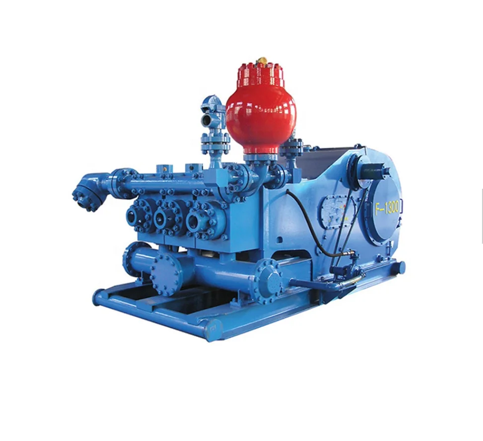
The 2,200-hp mud pump for offshore applications is a single-acting reciprocating triplex mud pump designed for high fluid flow rates, even at low operating speeds, and with a long stroke design. These features reduce the number of load reversals in critical components and increase the life of fluid end parts.
The pump’s critical components are strategically placed to make maintenance and inspection far easier and safer. The two-piece, quick-release piston rod lets you remove the piston without disturbing the liner, minimizing downtime when you’re replacing fluid parts.

If you run a mud rig, you have probably figured out that the mud pump is the heart of the rig. Without it, drilling stops. Keeping your pump in good shape is key to productivity. There are some tricks I have learned over the years to keeping a pump running well.
First, you need a baseline to know how well your pump is doing. When it’s freshly rebuilt, it will be at the top efficiency. An easy way to establish this efficiency is to pump through an orifice at a known rate with a known fluid. When I rig up, I hook my water truck to my pump and pump through my mixing hopper at idle. My hopper has a ½-inch nozzle in it, so at idle I see about 80 psi on the pump when it’s fresh. Since I’m pumping clear water at a known rate, I do this on every job.
As time goes on and I drill more hole, and the pump wears, I start seeing a decrease in my initial pressure — 75, then 70, then 65, etc. This tells me I better order parts. Funny thing is, I don’t usually notice it when drilling. After all, I am running it a lot faster, and it’s hard to tell the difference in a few gallons a minute until it really goes south. This method has saved me quite a bit on parts over the years. When the swabs wear they start to leak. This bypass pushes mud around the swab, against the liners, greatly accelerating wear. By changing the swab at the first sign of bypass, I am able to get at least three sets of swabs before I have to change liners. This saves money.
Before I figured this out, I would sometimes have to run swabs to complete failure. (I was just a hand then, so it wasn’t my rig.) When I tore the pump down to put in swabs, lo-and-behold, the liners were cut so badly that they had to be changed too. That is false economy. Clean mud helps too. A desander will pay for itself in pump parts quicker than you think, and make a better hole to boot. Pump rods and packing last longer if they are washed and lubricated. In the oilfield, we use a petroleum-based lube, but that it not a good idea in the water well business. I generally use water and dish soap. Sometimes it tends to foam too much, so I add a few tablets of an over the counter, anti-gas product, like Di-Gel or Gas-Ex, to cut the foaming.
Maintenance on the gear end of your pump is important, too. Maintenance is WAY cheaper than repair. The first, and most important, thing is clean oil. On a duplex pump, there is a packing gland called an oil-stop on the gear end of the rod. This is often overlooked because the pump pumps just as well with a bad oil-stop. But as soon as the fluid end packing starts leaking, it pumps mud and abrasive sand into the gear end. This is a recipe for disaster. Eventually, all gear ends start knocking. The driller should notice this, and start planning. A lot of times, a driller will change the oil and go to a higher viscosity oil, thinking this will help cushion the knock. Wrong. Most smaller duplex pumps are splash lubricated. Thicker oil does not splash as well, and actually starves the bearings of lubrication and accelerates wear. I use 85W90 in my pumps. A thicker 90W140 weight wears them out a lot quicker. You can improve the “climbing” ability of the oil with an additive, like Lucas, if you want. That seems to help.
Outside the pump, but still an important part of the system, is the pop-off, or pressure relief valve. When you plug the bit, or your brother-in-law closes the discharge valve on a running pump, something has to give. Without a good, tested pop-off, the part that fails will be hard to fix, expensive and probably hurt somebody. Pop-off valve are easily overlooked. If you pump cement through your rig pump, it should be a standard part of the cleanup procedure. Remove the shear pin and wash through the valve. In the old days, these valves were made to use a common nail as the shear pin, but now nails come in so many grades that they are no longer a reliable tool. Rated shear pins are available for this. In no case should you ever run an Allen wrench! They are hardened steel and will hurt somebody or destroy your pump.
One last thing that helps pump maintenance is a good pulsation dampener. It should be close to the pump discharge, properly sized and drained after every job. Bet you never thought of that one. If your pump discharge goes straight to the standpipe, when you finish the job your standpipe is still full of fluid. Eventually the pulsation dampener will water-log and become useless. This is hard on the gear end of the pump. Open a valve that drains it at the end of every job. It’ll make your pump run smoother and longer.

This website is using a security service to protect itself from online attacks. The action you just performed triggered the security solution. There are several actions that could trigger this block including submitting a certain word or phrase, a SQL command or malformed data.
A well-placed suction stabilizer can also prevent pump chatter. Pump chatter occurs when energy is exchanged between the quick opening and closing of the reciprocating pump’s valves and the hammer effect from the centrifugal pump. Pump isolation with suction stabilizers is achieved when the charge pumps are isolated from reciprocating pumps and vice versa. The results are a smooth flow of pumped media devoid of agitating energies present in the pumped fluid.
Explore a wide variety of mud pump valve on Alibaba.com and enjoy exquisite deals. The machines help maintain drilling mud circulation throughout the project. There are many models and brands available, each with outstanding value. These mud pump valve are efficient, durable, and completely waterproof. They are designed to lift water and mud with efficiency without using much energy or taking a lot of space.
The primary advantage of these mud pump valve is that they can raise water from greater depths. With the fast-changing technology, purchase machines that come with the best technology for optimum results. They should be well adapted to the overall configuration of the installation to perform various operations. Hence, quality products are needed for more efficiency and enjoyment of the machines" full life expectancy.
Alibaba.com offers a wide selection of products with innovative features. The products are designed for a wide range of flow rates that differ by brand. They provide cost-effective options catering to different consumer needs. When choosing the right mud pump valve for the drilling project, consider factors such as size, shape, and machine cost. More powerful tools are needed when dealing with large projects such as agriculture or irrigation.
Alibaba.com provides a wide range of mud pump valve to suit different tastes and budgets. The site has a large assortment of products from major suppliers on the market. The products are made of durable materials to avoid corrosion and premature wear during operations. The range of products and brands on the site assures quality and good value for money.

This invention relates to the circulation of fluid between the surface of a subterranean well and the bore hole and more specifically relates to the simultaneous control of drilling fluid circulation or mud pumps and a choke communicating with the pump.
Conventional apparatus used in rotary drilling operations includes a drilling fluid circulation pump or mud pump used to circulate drilling fluids from the surface through the well bore. These fluids are used to remove cuttings made by a rotary drill. In normal drilling fluid or mud circulation, the drilling fluid is pumped down through the drill pipe, discharged through the bit and returns to the surface in the annular space outside the drill pipe and inside the drill hole and casing placed in the well. The rate of drilling fluid circulation is determined by the necessary upward flow velocity required for removing cavings and drill cuttings from the hole and by the jetting requirements of the bit. The inherent advantage of the rotary system of drilling is that a fluid is circulated for the purpose of removing drill cuttings and maintaining a hole in such condition that the drill string can be withdrawn readily and returned to the bottom whenever necessary.
During conventional drilling it is not uncommon to encounter a sudden pressure increase or kick caused by the release of downhole liquids or gases under pressure which can affect drilling fluid circulation. When a kick is encountered, it can be necessary to vary the rate at which drilling fluid is injected into the well or to change the weight of the drilling fluid. A choke, in communication with the pump, is used to prevent significant pressure changes in conjunction with a change in the speed of operation of the mud pumps. For example, a significant increase in downhole pressure occurring as a result of an increase in the drilling fluid circulation can conceivably fracture the producing formation causing serious damage.
In normal drilling operations, the mud pumps are controlled by the driller, using a driller"s console located at the driller"s station on a rig to monitor relevant drilling parameters, including the speed of the mud pumps. Furthermore, conventional well control circulation operations also require manipulation of the choke to regulate or control the fluid pressure, especially during changes in the speed of the mud pump. On a conventional drilling rig, the choke is normally controlled from a choke console, which can be positioned on the drilling floor, at a position remote from the normal location of a driller"s console on a surface rig. Simultaneous control of both the mud pumps and the choke requires communication between the driller and one manning the choke console. Such communication is difficult, especially on engine driven drilling rigs. The noise and the use of different types of gauges on a rig cause confusion and makes such communication difficult, especially on engine driven drilling rigs. Furthermore, a more accurate gauge for pump strokes rate is conventionally located at the choke console, but conventional apparatus provide no means for using this more accurate gauge at the choke console to control the pumps. In a crisis situation, where the drilling crew is attempting to control the well, increased emphasis is placed on efficient communication and operation, which is difficult using prior art devices.
Apparatus for controlling the circulation of well control or kill fluid in a subterranean well includes a pump and a choke communicating with the pump to deliver drilling fluids from the surface of the well into the bore hole and return to the fluid handling equipment. Apparatus for monitoring the condition of the pump is normally employed at the driller"s console on the drilling rig and such pump monitoring apparatus includes a conventional pump control for regulating the speed and operation of the drilling fluid pumps. These pump controls can consist of pneumatic control valves or rheostats.
While control of the pump can be effected from the driller"s console, control of the choke can be simultaneously effected using a choke control apparatus located at a choke console, normally located on the drilling floor at a location remote from the driller"s console. A second pump control apparatus, again consisting of a conventional device, such as a pneumatic control valve or a rheostat, is located at the choke monitoring console and can be used to regulate pump speed and operation in the same manner as the first pump control apparatus located at the driller"s console. Apparatus is provided for overriding the first pump control upon transmission of a signal from the second pump control. Such apparatus can comprise a pneumatic valve unit or an electrical relay consisting of normally closed and normally open switches which change state upon actuation of the second pump control apparatus. In the preferred embodiment of this invention, the overriding signal is the same as the pump control signal. When this pump control signal is transmitted, a valve or relay functions to override the first pump control apparatus. Signals transmitted from the second pump control located at the choke console can then be transmitted to the pumps.
In the preferred embodiment of this invention, the overriding apparatus comprises a portion of an interface network located in the driller"s console, and the second pump control signal is transmitted from the choke console through the driller"s console and subsequently to the drilling fluid or mud pumps. In this manner, control of both the pump and the choke can be transferred to the same location on the drilling rig to provide for better control over both the rate of circulation of the drilling fluids and over the pressure maintained in the bore hole. Such centralized control is quite useful in certain situations, such as when a kick is encountered.
The preferred embodiments of the invention depicted herein are intended for use with conventional driller"s consoles and choke consoles employed on diesel or electrically powered rigs commonly used for drilling subterranean wells. The interface network and remote pump control apparatus employed in the choke console are consistent with conventional commercially available components of driller"s consoles and choke console.
FIG. 1 shows the conventional location of the driller"s console 2 and choke console 4 between which signals are transmitted to regulate or control both mud pumps 6 and the choke 8. The choke console 4 located proximate to the choke 8 separately controls the operation of the choke. The driller"s console 2 includes means for separately controlling the mud pumps 6 and signals may be transmitted from the choke console to the driller"s console for regulating the operation and speed of the mud pump. It can be seen from FIG. 2 that in the preferred embodiment of this invention the choke console controls the pumps by signals transmitted through the driller"s console 2. The transmission of signals between the various components shown in FIG. 2 can be by any of a number of conventional means, such as by electrical signals, by pneumatic or hydraulic signals, by fiber optic signals, by power line modulation, or in any other conventional form suitable for use on a drilling rig. A pneumatic control network for use with a diesel powered rig and an electrical interface network for use within an electrically powered drilling rig will be described herein.
FIGS. 3-5 depict the operation of a pneumatic interface network for a diesel powered rig. Only those portions of the pump control and the interface network relevant to the control of drilling fluid, circulating or mud pumps are depicted. Numerous other components are employed in a driller"s console or in a choke console. Such components are, however, conventional and the components shown in FIG. 3 are compatible with other conventional components controlling the operation of a drilling rig. The pneumatic interface network for the diesel powered rig shown in FIG. 3 is intended for use in controlling two mud pumps. On conventional drilling rigs, two or more mud pumps are employed, although it is common practice to use only a single mud pump at a time, retaining the other mud pumps for redundancy and/or for emergency situations. The two pneumatic control valves 12 and 26 contained within the driller"s console comprise conventional valves commonly employed in driller"s console. Valves manufactured by American Standard having a pressure range of 0 to 100 psi for clutch and throttle signals represent one conventional valve for controlling the mud pump. A plurality of shuttle valves 18, 20, 32 and 34, each comprising a dual input-single output valve, are employed on opposite sides of each of the first or main pneumatic control valves 12 and 26 for controlling the operation of the mud pumps. Shuttle valves 18, 20, 32 and 34 may comprise conventional valves, such as the P-54350-2 shuttle valve manufactured by Wabco, an American Standard Company. Of course other similar valves could be used to form the isolation function of these shuttle valves. Valve 70, also located at the driller"s console, comprises a four element stack valve unit consisting of valve elements 70a, 70b, 70c and 70d. Pneumatic valves 70 each comprise spring loaded, dual input, single output valves forming a valve stack 70. Individual valves are of conventional construction and comprise valves such as the A222PS valves manufactured by ARO Inc. which can be secured together by using an MKN stacking kit and an isolator plate manufactured by ARO Inc.
The pneumatic control valve 46 employed in the choke console comprises, in the preferred embodiment of this invention, an HD-2-FX pneumatic control valve having a pressure range from 0 to 100 psi, manufactured by American Standard. Pneumatic control valve 46 has a single input and three separate outputs. Valve 46 is located in the choke console and communicates with a conduit 40 providing air under pressure for use in actuating the various components depicted herein. A toggle switch 42 and an indicator light 44 are located on the choke console to insure that control is not transferred between the choke console and the driller"s console at a time when the differences in the throttle settings between the choke console and the driller"s console will create a serious pressure increase below the well, thus damaging the formation.
Three conduits 48, 50 and 52 extend from pneumatic control valve 46 to the driller"s console. Conduits 50 and 52 comprise the clutch C1 and clutch C2 signal paths for controlling the chokes 8 and communicate between the pneumatic control valve 46 and the individual valve units of stack valve 70. Clutch C1 line 52 is interconnected to shuttle valve element 20 and clutch C2 transmission line 50 is interconnected to shuttle valve 32. A T-conduit 54 is interconnected to the clutch C1 line 52 intermediate its ends and the T-conduit 54 establishes fluid communication between the clutch C1 line 52 and the first valve unit 70a. A separate branch 56 establishes communication between T-conduit 54 and another unit 70d of the stack. Each of the stack valves 70a-70d comprises a normally spring loaded valve in which the input from either rig air conduit 64 or from throttle valve line 48 passes directly through valve units 70a-70d. The T-conduit 54 and its adjoining conduit 56 lead from clutch line 52 and communicate with an actuator port on valve units 70a and 70d. Fluid pressure in conduit 54 and 56 serves to shift the pneumatic valve units 70a and 70d to close lines 64 or 48 when pressure is applied to clutch C1 conduit 52.
The clutch C2 line 50 extends the pneumatic control valve 46 into the driller"s console and communicates with shuttle valve 32. A T-conduit section 58 and branch 60 communicate with clutch C2 line 50 and with the remaining two valve units 70b and 70c at the actuator ports thereof. Pressure in clutch C2 line 50 will cause the valve units 70b and 70c to close against the action of a spring similarly disrupting the input from conduit 64 or 48 respectively.
The rig air input from conduit 64 into stack valve units 70a and 70b passes through lines 66 and 68 respectively to the pump control valves 12 and 26 when stack valves 70a and 70b are in the open position. Essentially, the stack valve units 70a and 70b are connected in parallel to the rig air source 64. The output conduits 61 and 62 leading from the stack valve units 70c and 70d are respectively connected to shuttle valves 18 and 34. Communication is normally established between throttle line 48 and valves 18 and 34 through the stack valve units 70c and 70d when the spring loaded valves are in their normally open position.
The first pneumatic control valves 12 and 26 comprise conventional elements for generating clutch and throttle signals in response to a constant pressure supply or rig air in conduit 64. For example, valve 12 generates a clutch signal in line 14 and a throttle signal in line 16. Clutch line 14 communicates with one of the two input ports of shuttle valve 20. Throttle line 16 communicates with one of the two input ports of shuttle valve 18.
FIG. 3 depicts a condition in which the mud pumps 6 and 6" can be controlled by using the first or primary mud pump controllers 12 and 26. It should be understood that in an actual practice, only one pump is normally used. Solid lines have been used to indicate that pneumatic signals communicate through the line, while dashed lines indicate that the line has been disabled and no signal is transmitted. As shown by the solid lines in FIG. 3, pressure in line 64, which is obtained from a source of rig air, communicates through the normally open stack valves 70a and 70b to lines 66 and 68 respectively. Rig air is then applied to pneumatic control valves 12 and 26. Referring to control valve 12, the presence of rig air at the input of this first control valve permits clutch and throttle signals to be generated in lines 14 and 16 respectively. Since the choke console pneumatic control valve is in the off position, as shown in FIG. 3, and there is no pressure in lines 48, 50 and 52, a pneumatic signal is applied in only one of the dual input ports of shuttle valves 18 and 20. A pneumatic clutch signal in line 14 can be transmitted through shuttle valve 20 and clutch line 22 directly to the drilling fluid or mud pump. Similarly, a throttle signal in line 16 would be transmitted through shuttle valve 18 and line 24 to the pump. Thus the pneumatic throttle and clutch signals to pump 6 are employed to control the operating speed of an internal combustion engine, for example, driving pump 6 and an operating clutch to engage or disengage the pump as desired or required.
FIG. 4 shows the condition in which the choke console pneumatic control valve 46 is actuated to apply a pneumatic signal in clutch line 52 and in throttle line 48. Pneumatic control valve 46 is of the type that actuation of a control lever in one direction will induce a clutch signal during initial movement and thereafter will produce a throttle signal. The pneumatic signal in clutch line 52 acts through lines 54 and 56 on the actuator ports of stack valve units 70a and 70d. Pressure applied at the actuator ports plugs the input lines to stack valve units 70a and 70d. Thus the rig air from line 64 is plugged by stack valve unit 70a thus disabling the first mud pump control valve 12 which comprises the primary means of regulating the mud pump 6 from the driller"s console. The pneumatic signal in line 52 is, however, transmitted to the second input port of shuttle valve 20. Since there is no pressure in line 14, any clutch signal in line 52 at shuttle valve 20 will be transmitted through line 22. The pneumatic signal in line 52 communicating with line 56 also disables the throttle input to stack valve unit 70d isolating shuttle valve 34 from the throttle line 48. Stack valve unit 70c, however, remains open and the pneumatic signal in throttle line 48 will be transmitted through line 61 to shuttle valve 18. This pneumatic signal in line 61 is in turn transmitted through throttle line 24 to the first mud pump. Similarly, the stack valve unit 70b remains open and rig air from conduit 64 flows through line 68 to the secondary driller mud pump control valve 26.
FIG. 5 shows the same pneumatic control circuit in which the choke console pump control valve 46 has been actuated to generate a pneumatic clutch C2 signal in line 50. This pneumatic signal in line 50 communicates through lines 58 and 60 to the actuating ports of stack valve units 70b and 70c to close the input ports from the rig air conduit 64 and from the throttle line 48 respectively. Valve units 70a and 70d, however, remain open. Rig air can thus be applied to pump control valve 12 and the pneumatic signal in throttle line 48 can be transmitted through stack valve unit 70d to one input port of shuttle valve 34. Similarly, the pneumatic signal in clutch C2 line 50 is transmitted to an input port of shuttle valve 32. A clutch signal derived from the pneumatic control valve 46 can thus be applied through line 36 to the second mud pump. Similarly, a throttle signal 38 determined by the position of pneumatic control valve 46 can be applied through shuttle valve 34 and line 38 to the second mud pump. Choke console pneumatic control valve 46 is of the type that actuation of an input lever in a first direction will apply a signal in clutch C1 line 52 and in throttle line 48, while actuation of the control valve unit in the opposite direction will result in the presence of a pneumatic signal in clutch C2 line 50 and in the throttle line 48. It will be understood that separate choke control elements are contained within the choke console for positioning the choke in the proper position. When the apparatus is in the configurations of FIGS. 4 and 5, the choke control valve 46 can also be used to control either mud pump 6 or mud pump 6".
FIG. 6 shows an electrical interface network for use with an electrically powered rig. Again, separate drillers and choke consoles can be used in the same manner as shown in FIG. 2. In this electrically powered network, rheostat 72 provides a control signal through path 88 and normally closed relay 84a and line 86 to an SCR housing for controlling the operation and speed of a single mud pump. A second rheostat 90 located on the choke console is normally isolated from SCR housing line 86 by a normally open relay 84b. The configuration of FIG. 6 shows the conventional operation of the mud pump 6 by means of the pump controlling rheostat 72 located in the driller"s console. When it is desired to control the mud pump by use of the choke mud pump control rheostat 90, switches 76 and 77 are closed. When switch 76 is closed, the relay 84 changes state and the normally open relay 84b is closed permitting regulation of the mud pump by the choke console mud pump rheostat 90. Closure of switch 76 results in the application of a voltage to the relay 84 thus changing the state of relays 84a and 84b to override the signal from the driller"s console mud pump rheostat 72 when it is desired to control the mud pump from the remote position of the choke console. Note that the common +V line 80 and ground line 82 lead between the driller"s console and the choke console. If for any reason these lines are severed, control of the mud pump automatically reverts to the driller"s console rheostat 72. Thus, the mud pump 6 or mud pump 6" can be controlled from the driller"s console or through the remote position of the choke console depending upon closure of electrical switch 76.

Present embodiments relate generally to the field of drilling and processing of wells, and, more particularly, to a mud saver valve for controlling flow of mud or other fluid during insertion of casing elements into a wellbore during drilling and completion operations and the like.
In conventional oil and gas operations, a drilling rig is used to drill a wellbore to a desired depth using a drill string, which includes drillpipe, drill collars and a bottom hole drilling assembly. During drilling, the drill string may be turned by a rotary table and kelly assembly or by a top drive to facilitate the act of drilling. As the drill string progresses down hole, additional tubular (e.g., drillpipe) is added to the drill string. Once the wellbore reaches a desired depth, the drill string may be removed from the wellbore and the completion phase may be initiated. The completion phase includes assembling downhole tubular (e.g., casing) and equipment used to enable production from an oil or gas well. During both drilling and completion phases, tubular may be assembled or coupled together to form tubular strings.
During drilling or completion of the well, the drilling rig may be used to insert joints or stands (e.g., multiple coupled joints) of tubular into the wellbore. As an example, during insertion of tubular into the wellbore by a traditional operation, each tubular element (e.g., each joint or stand) is coupled to an attachment feature, such as an elevator, that is in turn lifted by a traveling block of the drilling rig such that the tubular element is positioned over the wellbore. An initial tubular element may be positioned in the wellbore and held in place by gripping devices, such as slips or a spider, near the rig floor. Subsequent tubular elements may then be aligned with and coupled to the existing tubular elements in the wellbore to continue formation of the tubular string (e.g., casing string or drill string).
During insertion of tubular elements (e.g., casing) into a wellbore during completion operations, a flow of mud or other fluid may be pumped into the tubular elements and wellbore to facilitate the tubular or casing running operation. It is now recognized that certain aspects of these existing techniques are not optimal because of various limitations (e.g., equipment limitations) during certain phases of operation. For example, when a flow of mud or other fluid is circulated, mud or other fluid can inadvertently be spilled onto a rig floor during certain phases of operation. Existing valves to control the flow of mud during insertion and/or removal of tubular elements may be costly, susceptible to wear and corrosion, and so forth.
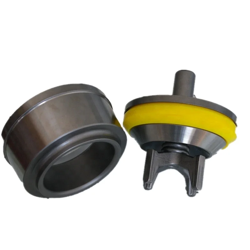
In accordance with one aspect of the disclosure, a system includes a mud saver valve assembly having a first sleeve, a second sleeve, and a first valve element axially captured between the first sleeve and the second sleeve, wherein the first valve element includes a support ring portion extending about a circumference of the first valve element and a center portion extending across the support ring portion, wherein the center portion comprises a dome-shaped geometry.
In accordance with another embodiment of the disclosure, a system includes a casing running tool configured to couple to a casing element and add the casing element from a casing string and a mud saver valve assembly disposed within the casing running tool, wherein the mud saver valve assembly is configured to flow a fluid through the casing running tool and into the casing element, the mud saver valve assembly includes a valve element extending across a flow path of the mud saver valve assembly, and the valve element is formed from an elastomer.
In accordance with a further aspect of the disclosure, a system includes an upper annular sleeve comprising a first axial recess, a lower annular sleeve comprising a second axial recess, a valve element axially captured between the upper annular sleeve and the lower annular sleeve, wherein the valve element includes a support ring extending about a circumference of the valve element, wherein the support ring has a first axial contour and a second axial contour and a dome-shaped center portion extending between the support ring, wherein the first axial contour is disposed within the first axial recess, the second axial contour is disposed within the second axial recess, and the valve element is formed from a rubber.
FIG. 3 is a partial cross-sectional side view of an embodiment of the mud saver valve assembly, illustrating a valve element captured between sleeves of the mud saver valve assembly;
FIG. 6 is a cross-sectional side view of a valve element of the mud saver valve assembly in an opened position, in accordance with present techniques; and
Present embodiments are directed to systems and methods for controlling circulation of mud or other fluid within a wellbore during insertion of tubular elements (e.g., casing) into a wellbore during wellbore completion operations and the like. A casing running tool (e.g., tubular running tool) may be used to facilitate assembly and disassembly of casing strings. Indeed, a casing running tool may be employed to engage and lift a tubular element (e.g., a casing joint or element), align the tubular element with a casing string, stab a pin end of the tubular element into a box end of the tubular string, engage the casing string, and apply torque to make-up a coupling between the tubular element and the casing string. Thus, a casing running tool may be employed to extend the tubular or casing string. Similarly, the casing running tool may be used to disassemble tubular or casing elements from a casing string by applying reverse torque and lifting the tubular elements out of the engagement with the remaining casing string. It should be noted that torque may be applied using a top drive system coupled to the casing running tool or integral with the casing running tool.
During a process of installing or removing tubular or casing elements, it may be desirable to circulate fluids (e.g., drilling mud) through the associated casing string. Accordingly, the casing running tool may be configured to create a flow path between the tubular handling equipment and the tubular or casing element such that fluid can efficiently pass from the casing running tool into the tubular element, and thereafter the casing string. In accordance with present embodiments, a flow of mud or other fluid through the tubular elements and within the wellbore may be regulated during insertion of the tubular or casing elements. For example, the flow of mud or other fluid may be automatically enabled when a casing running tool is coupled to a tubular element and/or when a mud pump for pumping drilling mud is in a pumping mode. The flow of mud or other fluid may be blocked when the casing running tool is decoupled from a tubular element or casing string and/or when the mud pump is not in a pumping mode. To this end, present embodiments include a mud saver valve assembly that may be disposed within or coupled to the casing running tool. The mud saver valve assembly includes a valve element configured to block mud or fluid flow when a fluid flow pressure applied to the valve element is below a threshold pressure, while enabling mud or fluid flow when the fluid flow pressure applied to the valve element is above the threshold pressure. For example, the threshold pressure may be equal to or greater than a head pressure of mud or fluid that may be contained in the casing running tool and/or a mud hose when the mud pump is not in a pumping mode. Thus, when the mud pump is not pumping mud or other fluid (e.g., when the casing running tool is not coupled to a tubular element to be added to a casing string), the valve element may block flow of mud or fluid still contained in the casing running tool or mud hose, thereby preventing inadvertent flow of mud from the casing running tool and onto a rig floor or platform. However, when the pressure applied to the valve element is greater than the threshold pressure (e.g., when the mud pump is in a pumping mode as the pipe drive system is coupling a tubular element to the casing string), the valve element enables flow of mud through the casing running tool and into the tubular element and casing string.
Turning now to the drawings, FIG. 1 is a schematic of a drilling rig 10 in the process of drilling a well in accordance with present techniques. While FIG. 1 represents the drilling rig 10 during a drilling and/or completion process, present embodiments may be utilized for disassembly processes and so forth. In particular, present embodiments may be employed in procedures including assembly or disassembly tubular elements, wherein it is desirable to provide and control fluid circulation through the tubular elements from a tubular handling system during assembly procedures.
In the illustrated embodiment, the drilling rig 10 features an elevated rig floor 12 and a derrick 14 extending above the rig floor 12. A supply reel 16 supplies drilling line 18 to a crown block 20 and traveling block 22 configured to hoist various types of equipment and tubular elements above the rig floor 12. The drilling line 18 may be secured to a deadline tiedown anchor. Further, a drawworks may regulate the amount of drilling line 18 in use and, consequently, the height of the traveling block 22 at a given moment. Below the rig floor 12, a casing string 28 extends downward into a wellbore 30 (e.g., a pre-drilled wellbore) and is held stationary with respect to the rig floor 12 by a rotary table 32 and slips 34. A portion of the casing string 28 extends above the rig floor 12, forming a stump 36 to which another tubular element or length of casing 38 is in the process of being added.
The length of casing 38 is held in place by a casing running tool 40 that is hanging from the traveling block 22. Specifically, a gripping device 42 of the casing running tool 40 is engaged about an outer perimeter of a distal end 44 of the casing 38. This attachment via the gripping device 42 enables the casing running tool 40 to maneuver the casing 38. In the illustrated embodiment, the casing running tool 40 is holding the casing 38 in alignment with the stump 36. The gripping device 42 may include an integral seal or may be configured to couple with the casing 38 about a seal such that a sealed passage is established between the casing running tool 40 and the casing 38. Establishing this sealed passage facilitates circulation of fluid (e.g., drilling mud) through the casing running tool 40 into the casing 38 and the casing string 28. Further, the gripping device 42 couples with the casing 38 in a manner that enables translation of motion to the casing 38. Indeed, in the illustrated embodiment, the casing running tool 40 includes a top drive 46 configured to supply torque for making-up and unmaking a coupling between the casing 38 and the stump 36. It should be noted that, in some embodiments, the top drive 46 is separate from the casing running tool 40.
To facilitate the circulation of mud or other drilling fluid within the wellbore 30, the drilling rig 10 includes a mud pump 48 configured to pump mud or drilling fluid up to the casing running tool 40 through a mud hose 50. In certain embodiments, the mud hose 50 may include a stand pipe 52 coupled to the derrick 14 in a substantially vertical orientation to facilitate pumping of mud. The stand pipe 52 provides a high-pressure path for mud to flow up the derrick 14 to the casing running tool 40. From the mud hose 50 (e.g., stand pipe 52), the mud flows through a kelly hose 53 to the casing running tool 40. From the casing running tool 40, the drilling mud will flow through internal passages of the gripping device 42, into internal passages of the casing 38 and the casing string 28, and into the wellbore 30 to the bottom of the well. The drilling mud flows within the wellbore 30 (e.g., in an annulus between the casing string 28 and the wellbore 30) and back to the surface where the drilling mud may be recycled (e.g., filtered, cleaned, and pumped back up to the casing running tool 40 by the mud pump 48).
The illustrated embodiment of the drilling rig 10 further includes a controller 54 having one or more microprocessors 56 and a memory 58. The memory 58 is a non-transitory (not merely a signal), computer-readable media, which may include executable instructions that may be executed by the microprocessor 56. The controller 54 is configured to regulate operation of the mud pump 48 and/or other features of the drilling rig 10. For example, the controller 54 may be configured to regulate a flow rate of mud or other drilling fluid circulated through the casing string 28 and the wellbore 30 during installation of tubular elements (e.g., casing 38). For example, the controller 52 may regulate operation of the mud pump 48 to start, stop, increase, and/or decrease mud flow into the casing string 28 and wellbore 30 during installation of casing 38 elements. The controller 52 may also regulate other components of the drilling rig 10 to control flow of drilling mud. For example, the controller 52 may control operation of the casing running tool 40 and/or a valve disposed along the mud hose 50.
As discussed in detail below, the casing running tool 40 also includes a mud saver valve assembly 60. When a new length of casing 38 is to be added to the casing string 28, mud flow from the pump 48 and the mud hose 50 is stopped, and the casing running tool 40 (e.g., the gripping device 42) is removed from the casing string 28 (i.e., the length of casing 38 most recently added to the casing string 28). When the casing running tool 40 releases the casing string 28, mud within the casing running tool 40 may run out of the casing running tool 40 and onto the rig floor 12. To avoid spilling mud onto the rig floor 12, the casing running tool 40 includes the mud saver valve assembly 60 to block flow of mud from out of the casing running tool 40 when the mud pump 48 is not pumping mud. When the casing running tool 40 is thereafter coupled to a new length of casing 38 and the mud pump 48 resumes a pumping operation, the mud saver valve assembly 60 automatically enables flow of mud through the mud saver valve assembly 60 and the casing running tool 40 to the casing 38 and casing string 28.
As described below, the mud saver valve assembly 60 includes a valve element configured to block mud flow through the mud saver valve assembly 60 when the mud pump 48 is not running (e.g., pumping) and/or when the casing running tool 40 is decoupled from the casing 38 and/or casing string 28. In this manner, the mud saver valve assembly 60 may block mud remaining in the casing running tool 40, kelly hose 53, and/or mud hose 50 (e.g., stand pipe 52) from inadvertently flowing out of the casing running tool 40 and onto the rig floor 12 when the casing running tool 40 is decoupled from the casing 38. When the mud pump 48 is running and pumping a mud flow (e.g., when the casing running tool 40 is coupled to casing 38), the valve element may automatically enable flow of mud through the casing running tool 40 and into the casing 38. For example, the valve element may have a material construction, geometry, and/or shape that enables blockage of mud flow when the mud pump 48 not pumping, while enabling automatic flow of the mud when the mud pump 48 is pumping. As discussed further below, the valve element of the mud saver valve assembly 60 may also be formed from a durable, resilient, corrosion resistant material, thereby enabling improved longevity and useful life of the valve element and the mud saver valve assembly 60.
FIG. 2 is a cross-sectional side view an embodiment of the mud saver valve assembly 60, illustrating a valve element 80 captured between sleeves 82 of the mud saver valve assembly 60. More specifically, the valve element 80 is axially captured between an upper sleeve 84 and a lower sleeve 86. For example, the upper and lower sleeves 84 and 86 may be tubes or annular members, and the valve element 80 may have a generally circular outer diameter. In other embodiments, the upper and lower sleeves 84 and 86 and the valve element 80 may have other geometries (e.g., square, rectangular, polygonal, elliptical, etc.). As mentioned above, the mud saver valve assembly 60 is coupled to (e.g., positioned within) the casing running tool 40. For example, the mud saver valve assembly 60 may be threaded, bolted, clamped, or otherwise mechanically attached to the casing running tool 40. The upper and lower sleeves 84 and 86 generally define a flow path 85 through which a flow of drilling mud or other fluid may flow through the casing running tool 40 and into the casing element 38. When the casing running tool 40 is coupled to a length of casing 38, the mud saver valve assembly 60 is inserted axially into (e.g., “stabbed” into) the casing 38. In this manner, drilling mud may flow from the casing running tool 40, through the mud saver valve assembly 60, as indicated by arrow 88, and into the casing 38 when the mud pump 48 is pumping. As will be appreciated, the mud saver valve assembly 60 and/or the casing running tool 40 may include seals 89 (e.g., O-rings, axial seals, annular seals, etc.), gaskets, and/or other components configured to enable a flow of mud or other fluid through the casing running tool 40, the mud saver valve assembly 60, and the casing 38.
As mentioned above, the valve element 80 is configured to block mud flow through the mud saver valve assembly 60 and, thus, the casing running tool 40 when the mud pump 48 is not pumping, while automatically enabling mud flow through the mud saver valve assembly 60 and, thus, the casing running tool 40 when the mud pump 48 is pumping. To this end, the valve element 80 is formed from a flexible, yet resilient, material. For example, the valve element 80 may be formed from a rubber (e.g., steel-belted rubber), polyurethane, neoprene, other elastomer, or other suitable material. In certain embodiments, the valve element 80 may be a single molded piece. Additionally, to enable blockage of flow and/or retention of mud within the casing running tool 40 when the mud pump 48 is not in a pumping mode, the valve element 80 has a dome-shaped geometry or shape. Details and functionalities of the dome-shaped geometry of the valve element 80 are discussed in further detail below with reference to FIGS. 4-6. The sleeves 82 of the mud saver valve assembly 60 may be formed from any suitable and durable (e.g., corrosion and/or wear resistant) material, such as steel, plastic, or other material.
FIG. 3 is a partial cross-sectional side schematic view, taken within line 3-3 of FIG. 2, of the mud saver valve assembly 60, illustrating axial capture of the valve element 80 between the sleeves 82. The upper and lower sleeves 84 and 86 are coupled to one another, as indicated by arrow 100, with the valve element 80 at least partially between the upper and lower sleeves 84 and 86. In certain embodiments, the upper and lower sleeves 84 and 86 may be coupled to one another via a threaded connection, a shrink fit, an interference fit, bolts, clamps, or other fasteners. In the illustrated embodiment, the upper sleeve 84 is disposed about the lower sleeve 86, but in other embodiments the lower sleeve 86 may be disposed about the upper sleeve 84. In yet another embodiment, the upper and lower sleeves 84 and 86 may at least partially axially abut one another. Furthermore, the upper and lower sleeves 84 and 86 may include seals, gaskets, or other components disposed therebetween to block leakage of drilling mud or fluid from the mud saver valve assembly 60.
As discussed below, the valve element 80 includes a support ring portion 102 (e.g., radially outer ring) and a center portion 104 (e.g., dome-shaped portion). The support ring portion 102 is axially captured and retained between the upper and lower sleeves 84 and 86. To facilitate the axial capture of the valve element 80, the support ring portion 102 has an upper axial contour 106 and a lower axial contour 108. The upper axial contour 106 of the support ring portion 102 is received (e.g., nested within) a corresponding axial recess 110 of the upper sleeve 84 having a similar contour. Likewise, the lower axial contour 108 of the support ring portion 102 is received (e.g., nested within) a corresponding axial recess 112 of the lower sleeve 86 having a similar contour. When the upper and lower sleeves 84 and 86 are coupled to one another, the upper axial contour 106 and the lower axial contour 108 of the support ring portion 102 are captured by the axial recess 110 and the axial recess 112, respectively, thereby securing the support ring portion 102 and, thus, the valve element 80 between the upper and lower sleeves 84 and 86. When the valve element 80 is axially captured by the upper and lower sleeves 84 and 86, the center portion 104 extends across the flow path 85 of the mud saver valve assembly 60.
FIG. 4 is a perspective view of the valve element 80, illustrating the support ring portion 102 and the center portion 104. As described above, the support ring portion 102 is axially captured between the upper and lower sleeves 84 and 86 to secure the valve element 80 within the mud saver valve assembly 60. The center portion 104, which extends between the circular support ring portion 102, is exposed to an interior (e.g., flow path 85) of the mud saver valve assembly 60. Thus, the center portion 104 is exposed to a mud flow within the casing running tool 40.
As mentioned above, in one embodiment, the valve element 80 is formed from a flexible, yet resilient, material, and the center portion 104 has a dome-shaped configuration. The center portion 104 is further divided into sections or segments 120. More specifically, the center portion 104 is cut or sliced to divide the center portion 104 into the segments 120. For example, in the illustrated embodiment, the center portion 104 has two slits 122 extending across a diameter or width of the center portion 104 at approximately 90 degrees relative to one another. As a result, the center portion 104 is divided into four segments 120. Other embodiments of the valve element 80 may include other numbers of slits 122 (e.g., diameter slits and/or radial slits) to divide the center portion 104 into other numbers of segments 120 (e.g., 3, 5, 6, 7, or more segments 120). As will be appreciated, the individual segments 120 may move (e.g., bend) independently from one another.
FIG. 5 is a cross-sectional side view of the valve element 80, illustrating the dome-shaped configuration of the center portion 104. While the flexible, resilient material of the valve element 80 enables deformation (e.g., bending) of the segments 120 of the center portion 104, the dome-shaped configuration of the center portion 104 enables the valve element 80 to withstand a threshold pressure (e.g., stagnant drilling mud in the casing running tool 40 when the mud pump 48 is not pumping mud) without deformation of the segments 120. The number of segments 120, the type of material, the length of the slits 122, the size of the valve element 80, and so forth, may be calibrated based on empirical data to fully/partially open at certain pressures.
A concave side 140 of the center portion 104, which is exposed to the drilling mud flow from the casing running tool 40 (e.g., an upstream direction of the drilling mud flow), may withstand a threshold pressure (e.g., amount of drilling mud) applied to the concave side 140 of the center portion 104 without deforming to the point that the pressure (e.g., drilling mud) traverses or flows past the center portion 104. As will be appreciated, the threshold pressure of the concave side 140 of the center portion 104 may generally correspond to a pressure head of drilling mud that may be within the casing running tool 40, kelly hose 53, and/or stand pipe 52 when the casing running tool 40 is decoupled from the casing string 28 and the mud pump 48 pumping operation is suspended. The particular threshold pressure that the concave side 140 of the center portion 104 can withstand without allowing the pressure to traverse the center portion 104 (e.g., via excessive bending of the segments 120) may be selected by adjusting various design parameters of the center portion 104 and/or the valve element 80. For example, a material of a particular resilience may be selected to manufacture the valve element 80, such that the segments 120 do not deform and open the valve element 80 until a particular pressure applied to the concave side 140 is reached. Additionally, a number of segments 120, a thickness 142, and/or a radius of curvature 144 of the center portion 104 may be selected to achieve a desired pressure withstanding capability of the concave side 140 of the valve element 80. In certain embodiments, parameters of the valve element 80 (e.g., material resilience, number of segments 120, thickness 142, and/or radius of curvature 144) may be selected to achieve a threshold pressure of 50, 60 70, 80, 90, 100, 110, 120 pounds per square inch, or more.
Moreover, pressure (e.g., drilling mud) below the threshold pressure that is applied to the concave side 140 of the center portion 104 may improve a seal created by the center portion 104 when the mud pump 48 is not pumping mud to the casing running tool 40. For example, as indicated by arrows 146, pressure applied to the concave side 140 of the center portion 104 may cause the segments 120 of the center portion 104 to press against one another due to the dome-shaped configuration of the center portion 104. That is, a seal interface 148 (e.g., at slits 122) between adjacent segments 120 may be strengthened, as indicated by arrows 150, as a pressure below the threshold pressure is applied to the concave side 140. In this manner, the sealing capability of the valve element 80 when the mud pump 48 is not pumping mud to the casing running tool 40 may be improved, thereby further reducing inadvertent leaking of mud or fluid out of the casing running tool 40 (e.g., and onto the rig floor 12) when the casing running tool 40 is decoupled from the casing 38 or casing string 28.
As the valve element 80 and mud saver valve assembly 60 are oriented such that the concave side 140 of the center portion 140 is exposed to the flow of drilling mud within the casing running tool 40, the convex side 152 of the center portion 104 is exposed to the interior of the casing 38 and/or casing string 28 when the casing running tool 40 is coupled to the casing 38 and/or casing string 28. In other words, the convex side 152 is exposed to a downstream side of the mud saver valve assembly 60 relative to a drilling mud or fluid flow. As will be appreciated, the segments 120 will more readily and easily deform (e.g., bend) upon application of a pressure to the center portion 104 from the convex side 152. This may provide additional benefits. For example, the ability of the segments 120 to more easily deform when a pressure 154 (e.g., backpressure within the casing string 28) is applied to the convex side 152 of the valve element 80 may facilitate pressure equalization across the valve element 80.
FIG. 6 is a cross-sectional side view of the valve element 80, illustrating deformation of the segments 120 of the center portion 104 of the valve element 80 when a pressure greater than the threshold pressure is applied to the concave side 140 of the center portion 104. As discussed above, the threshold pressure that the concave side 140 of the center portion 104 may withstand and remain sealed may correspond to a pressure head of drilling mud that may be within the casing running tool 40, kelly hose 53, and/or stand pipe 52 when the casing running tool 40 is decoupled from the casing string 28 and the mud pump 48 pumping operation is suspended. However, when the mud pump 48 pumping operation resumes (e.g., when the casing running tool 40 is coupling another length of casing 38 to the casing string 28), the pressure of the drilling mud on the concave side 140 may exceed the threshold pressure, thereby causing the segments 120 to bend (e.g., invert) and, thus, open the valve element 80 to allow flow of drilling mud from the casing running tool 40 and into the casing 38 and casing string 28. After the casing 38 is added to the casing string 28 and another length of casing 38 is to be added, the mud pump 48 pumping operation may be suspended, thereby dropping the pressure applied to the concave side 140 of the center portion 104, and the segments 120 may revert back to their natural or normal shape, as shown in FIG. 5, to close the valve element 80. In this manner, inadvertent flow of drilling mud from the casing running tool 40 (e.g., onto the rig floor 12) may be blocked when the casing running tool 40 is not coupled to casing 38 to be added to the casing string 28.
In certain embodiments, the mud saver valve assembly 60 may include more than one valve element 80. For example, FIG. 7 is a schematic side view of an embodiment of the mud saver valve assembly 60 having two valve elements 80 (e.g., a first valve element 180 and a second valve element 182) disposed in series with one another. Other embodiments of the mud saver valve assembly 60 may have other numbers (e.g., 3, 4, 5, or more) of valve elements 80. Additionally, the respective orientations of the valve elements 80 may vary. For example, one embodiment having two valve elements 80, the concave side 140 of one valve element 80 may face an upstream direction, and the concave side 140 of a second valve element 80 may face a downstream direction. For example, the concave side 140 of the first valve element 180 may face an upstream direction, and the concave side 140 of the second valve element 182 may face a downstream direction, or vice versa.
The illustrated mud saver valve assembly 60 includes the upper and lower sleeves 84 and 86 and also an intermediate sleeve 184. The first valve element 180 is axially captured by the upper sleeve 84 and the intermediate sleeve 184, and the second valve element 182 is axially captured by the intermediate sleeve 184 and the lower sleeve 86. As will be appreciated, the first and second valve elements 180 and 182 may have similar features as the valve element 80 described above. In certain embodiments, the first and second valve elements 180 and 182 may be designed to have the same threshold pressure, while in other embodiments the first and second valve elements 180 and 182 may be designed to have different threshold pressures. For example, in one embodiment, the first valve element 180 may have a first threshold pressure, and the second valve element 182 may have a second threshold pressure that is lower than the first threshold pressure of the first valve element 180. Additionally, the upper sleeve 84, lower sleeve 86, and intermediate sleeve 184 may have similar features as the upper and lower sleeves 84 and 86 described above.
As discussed in detail above, present embodiments include the mud saver valve assembly 60, which may be used with the casing running tool 40 or other component of the drilling rig 10. The mud saver valve assembly 60 is configured to automatically enable the flow of mud or other fluid through the casing running tool 40 when the casing running tool 40 is coupled to the casing element 38 and/or when the mud pump 48 is in a pumping mode (e.g., during a casing running operation). The mud saver valve assembly 60 is further configured to block the flow of mud or other fluid through the casing running tool 40 when the casing running tool 40 is decoupled from the casing element 38 or the casing string 28 and/or when the mud pump 48 is not in a pumping mode. The mud saver valve assembly 60 includes the valve element 80, which is configured to block mud or fluid flow when a pressure applied to the valve element 80 is below a threshold pressure, while automatically enabling mud or fluid flow when the pressure applied to the valve element 80 is above the threshold pressure. For example, the threshold pressure may be equal to or greater than a head pressure of mud or fluid that may be contained in the casing running tool tem 40 and/or a mud hose 50 when the mud pump 48 is not in a pumping mode. Thus, when the mud pump 48 is not pumping mud or other fluid (e.g., when the casing running tool 40 is not coupled to the casing element 38 to be added to the casing string 28), the valve element 80 may block flow of mud or fluid still contained in the casing running tool 40 and/or mud hose 50, thereby blocking inadvertent flow of mud from the casing running tool 40 and onto the rig floor 12. However, when the pressure applied to the valve element 80 is greater than the threshold pressure (e.g., when the mud pump 48 is in a pumping mode as the casing running tool 40 is coupling the casing element 38 to the casing string 28), the valve element 80 automatically enables flow of mud through the casing running tool 40 via deformation (e.g., bending or inverting) of the segments 120 of the valve element 80.
Embodiments of the valve element 80 described above provide additional improvements over exiting mud saver valves. For example, the valve element 80 may be formed from a durable, corrosion resistant, resilient, and wear resistant material, such as rubber, neoprene, or other elastomer. Thus, the valve element 80 may be less costly to produce, while also providing increased useful life. Moreover, the dome-shaped configuration of the valve element 80 enables the valve element to withstand a threshold pressure (e.g., head pressure of mud within the pipe drive system 40 and/or mud hose 50) in a first direction (e.g., direction of mud flow), while also enabling the valve element 80 to equalize pressure across the mud saver valve assembly 60 in a second direction (e.g., to accommodate backpressure within the casing string 28).

Cavitation is an undesirable condition that reduces pump efficiency and leads to excessive wear and damage to pump components. Factors that can contribute to cavitation, such as fluid velocity and pressure, can sometimes be attributed to an inadequate mud system design and/or the diminishing performance of the mud pump’s feed system.
When a mud pump has entered full cavitation, rig crews and field service technicians will see the equipment shaking and hear the pump “knocking,” which typically sounds like marbles and stones being thrown around inside the equipment. However, the process of cavitation starts long before audible signs reveal themselves – hence the name “the silent killer.”
Mild cavitation begins to occur when the mud pump is starved for fluid. While the pump itself may not be making noise, damage is still being done to the internal components of the fluid end. In the early stages, cavitation can damage a pump’s module, piston and valve assembly.
The imperceptible but intense shock waves generated by cavitation travel directly from the fluid end to the pump’s powe


 8613371530291