
what is the function of pulsation dampener on mud pump pricelist
This equipment plays an important role as an accessory to Yamada air-operated double diaphragm pumps. The pulsation dampener serves to reduce pulsation produced in operation and to assure stable discharge flow and pressure.
When pulsations occur with pump operation, it will result in the pressure in Chamber Bbeing greater than that in Chamber A. The diaphragm will act as an air cushion and automatically adjust to this pressure change and absorb the pulsations.
This operation will shift the center rod position upwards and allow more air in Chamber Athrough the air inlet, returning the diaphragm to a neutral position. If liquid pressure decreases, air pressure in Chamber Acauses the diaphragm to move downward, shifting shaft location and changing valve position, releasing excess air pressure in Chamber Awhich returns diaphragm to a neutral position. This action causes a reduction in surges and pulsation caused by a air operated double diaphragm pumps

Mud Pump Pulsation Dampener is usually installed on the discharge line to reduce the fluctuation of pressure and displacement of the drilling mud pump.
Mud Pump Pulsation Dampener is a pneumatic device built into the outflow line of each UUD pump to dampen the pressure fluctuations resulting from the action of the pump. Although presented as a surge tank, this device is really a device that can be tuned to greatly diminish the output pulsations transmitted downstream from the mud pump. Unfortunately, the effectiveness of the pulsation dampener is a function of both output pump pressure and frequency of the pump pulsations.
Positive displacement pumps effectively pump fluid at a constant average flow rate. However, because the individual pumping elements of these pumps discharge discrete quantities of fluid, the instantaneous flow rate varies in a cyclic fashion.
Pulsations are observed in the system as pressure spikes. In the positive displacement pump family, single-shoe peristaltic pumps generally create the largest pulse, followed by two-shoe peristaltic pumps. Triplex and quintuplex pumps have smooth output curves because of piston overlap. Gear pumps can have extremely small pulses, but pulsations still exist. This pulsating flow can cause operational problems and shorten equipment’s service life.
To alleviate the problem, pulsation dampeners can be added to the pumping system to absorb pressure spikes and smooth fluid flow. Figure 1 shows the undampened pressure spikes from a triplex pump in green. The dampened pressure curve from the same pump with the same system settings are indicated in blue. Six pulses per revolution occur instead of the expected three. This is a result of piston overlap.
The most common type of pulsation dampener is a hydro-pneumatic pressure vessel containing compressed air or nitrogen and a bladder—or bellows—that separate the process fluid from the gas charge. To maximize the dampening effect, pulsation dampeners should be installed as close as possible to the pump discharge with a gas charge that is slightly below the normal system pressure. More important, pulsation dampeners must be properly sized for the system.
A dampener that is undersized cannot adequately compensate for pressure and flow fluctuations. An oversized dampener will act as an accumulator, storing too much fluid. This will cause slow stabilization and a delayed response to system changes. The first step in sizing a dampener is to quantitatively define the acceptable performance.
The specific requirements of the application and the components that make up the system are all factors that need to be considered. Once an acceptable pressure variation is defined, the unit size required for the desired performance should be determined. Engineers and designers are interested in making accurate predictions. Avoiding a problem is better than finding a way to fix it.
Sizing pulsation dampeners is straightforward. However, calculating the system pressure fluctuations is more complex. Fluid discharge rates from pumps are difficult to mathematically model. For example, in Figure 1, the spikes are not even. Theoretically, they should be equal. Mathematical models must be physically tested to verify their accuracy.
Pumps with multiple heads and higher pulse frequencies can make the calculations more difficult. The distance from one output port to the next is generally not constant. This creates a shift in the piston overlap with intermittent larger and smaller pulses. Calculating the magnitude or frequency of noise pulses that can develop or resonate in a system is difficult.
Piping arrangement—such as bends, reducers and valves—combined with the opening and closing of pump discharge check valves can create noise in the fluid called pressure pulses. Because many variables must be considered, each pump type should be tested with and without a dampener. The pressure curve data can be recorded and used to find the pump’s formula constant. This constant can be used in future calculations. As long as other pump models are similar to the test unit, accurately predicting the magnitude of line pressure variation with a given size dampener is possible.
The pressure in a piping system will rise sharply when a volume of fluid is added to the line. It accelerates the mass of the fluid in the piping system. This is acceleration head, and it needs to be minimized with a dampener. The effect and its impact must be considered on both the inlets and outlets of positive displacement pumps. On the inlet side, cavitation and partial filling of pump cavities can damage pump components and make the pump much louder than normal.
A non-snubbed pressure transducer can accurately measure the system’s pressure spikes. A pressure transducer can react much faster than a bourdon tube gauge, and it can measure noise if the sample rate is high enough.
Bourdon tube gauges require time to equalize and can undershoot and overshoot the actual pressure depending on the magnitude and frequency of the pressure pulse. Even if the gauge could read accurately, reading a quickly moving dial is difficult. Electronically measured and recorded data can determine how the system is operating.
System noise must be considered when taking measurements because it can give higher-than-expected results. Noise in the pumping liquid can generally be ignored, but in some situations, system noise needs to be controlled. Noise can cause pressure relief valves to leak, damage sensitive components and create occupational safety hazards. Dampeners typically reduce noise, and some are specifically designed for this purpose.
Several different styles of dampeners are available, and each has advantages and disadvantages. This article focuses on reducing the pressure pulses caused by pulsing flow. The principles and the method for calculating the appropriate size dampener for this application are the same for most dampeners.
A dampener absorbs a fluid pulse and then allows the fluid to flow back into the system between pulses. Most dampeners use a gas charge that is set slightly below the normal system pressure and is compressed by the pulse of fluid. The gas then expands when fluid is released.
In this formula, n is a constant that is specific to the gas being used. For example, for air at room temperature, n ≅ 1.4, and for nitrogen, n ≅ 1.399.
Some heat transfer almost always occurs. The process is rarely slow enough for the gas temperature to equalize, so the actual answer will be between these two calculations. In most cases, the fluctuations are fast enough that the actual value is significantly closer to the isentropic formula. The isentropic formula gives the most conservative result. Therefore, it is the more accurate formula in most cases.
In actual practice, either formula would probably work if the pressure fluctuations are small relative to the system pressure. The pump constant that is developed would cover the inaccuracies in the formula as long as the pressure variations are similar. In this article, the isentropic formula is used.
To determine the pump constant, the volume from a single pulse of the pump must first be determined. Then an initial estimate of dampener size is made, and the corresponding value of dampener volume is applied. The amount of gas in the dampener will be less than the total dampener volume, which needs to be factored into the calculation. A typical range of 80 to 90 percent of the dampener volume should be gas if the dampener is properly charged. These give an initial gas volume:
The constant reduces the pulse volume to account for flow leaving the dampener while the pulse is entering. It also accounts for piston overlap, which changes the effective size of the pulse. Adding the factor to the isentropic formula and solving for the pump factor gives us the following equation:
For example, the pressure curve from an undampened, two-shoe, 2.5-inch peristaltic hose pump shows a sharp increase in flow, followed by a “no-flow” or negative flow zone. In this instance, the line has a ball valve that is creating the flow restriction for back pressure. The blue line shows the undampened pressure spikes (see Figure 2). The red line shows the pressure changes of the same pump with the same back pressure valve setting but now using a dampener. This sample dampener has an actual gas volume of 415 cubic inches, and the dampener is 90-percent gas filled. The base pressure is 14.15 psig, and the pulse is 76.9 cubic inches. If the pressure fluctuation is calculated using the isentropic pressure formula, the result is:
It is important to remember to add 14.7 psi to convert from gauge to absolute pressure, then subtract 14.7 psi again to get the final result in gauge pressure. This pump setup was tested, and the actual pressure variation was determined to be 7.38 psi. Therefore, the result is:
If the example above is used and it is decided that a pressure fluctuation of 15 psi would be acceptable, the formula with the previously calculated pump factor can be used to determine what size of dampener is needed.
Table 1 lists some approximate pump constant factors that can be used when sizing dampeners for different pump types. These factors are approximate, and the results may vary significantly with the many variables involved.
A triplex plunger pump doses methanol, which is metered on the discharge side. Without a dampener to control pulsations and smooth out the flow, the installed flow meters were giving inaccurate readings.
When using a triplex pump, all three chambers of the pump must stay full of fluid with no voids. Any voids or pockets can cause seal leakage, pump vibration and excess pump noise.
The solution was to install a pulsation dampener at the pump discharge to smooth the flow and remove pressure pulsations. This allowed the dosing to be more accurate. An inlet stabilizer (suction dampener) was also installed on the inlet side of the pump to act as an accumulator to keep the pump chambers filled. The inlet stabilizer also removed pulsations created by the pump on its inlet stroke. Both devices were sized based on the pump type, flow rate and operating pressure.
During the filling of a drum with a flexible hose, an automatic valve would close and cause a water hammer effect. All the pipes leading into the system would shake until they broke loose from their supports. The solution was to install a pulsation dampener at the beginning of the flexible hose connection.
The pulsation dampener was sized based on the flow parameters and installed at the beginning of the flexible hose. When the automatic valve closed, the hose and pulsation dampener effectively absorbed a portion of the water hammer, eliminating pipe shake and improving operational safety.
The sizing of a pulsation dampener is critical to achieving the desired result. Finding and using the correct constant pump factor in dampener sizing is a key part of the solution. As long as the pulsation dampener is properly sized, positioned and charged, it will effectively dampen pulsations to protect equipment and keep the pressure pulses within design parameters.

A pulsation dampener reduces or eliminates the variations in pressure and flow produced by reciprocating pumps. In many applications, low frequency pressure waves cause problems within a given piping system and/or process. Eccentric, cam-driven pumps are probably the most commonly applied for services that require pulsation dampening, e.g., metering pumps and reciprocating (power) pumps.
Pulsation dampeners are found in a variety of designs, but for our purposes we will focus on only gas-charged pulsation dampeners, which rely on a calculated volume of compressed gas, usually Nitrogen, which is alternately compressed and expanded in synchronization with the pump plunger to reduce or eliminate pressure pulsations. This gas volume is normally separated from the process fluid by a flexible membrane. Common membrane designs include elastomeric bladders, PTFE diaphragms, PTFE bellows or stainless steel bellows.
Pressure waves or pulses are a consequence of the alternating acceleration and deceleration of fluid velocity corresponding to the travel of the piston or plunger. The pattern and amplitude of these pulses varies with pump configuration, specifically the number and size of pistons, as well as fluid compressibility factors.
It is precisely the fluid volume above mean on the discharge cycle of each stroke, which induces these pressure pulsations into a piping system. The number of pistons offered by the pump—given that all are of identical diameter and equally phased—displace a known peak volume above mean. These constants may be influenced by fluid compressibility, but for the purpose of this explanation we’ll assume none at this point. A pulsation dampener absorbs only that portion of piston displacement above mean flow, and then stores it momentarily before discharging it during the portion of the cycle below mean flow (on the suction stroke).
A simplex pump displaces a volume of fluid above mean that is equal to about 60 percent of total displacement. A duplex pump displaces a lower fluid volume above mean, approximately half that of a simplex pump. Pumps of three or more pistons of equal diameter, stroke length and proportionally phased will always present a very small fluid volume above mean to the piping system. A triplex pump, for example, produces about a 4 percent peak, as long as fluid compressibility factors and pump efficiencies are not at issue.
These smaller fluid volumes are accounted for by the crank angle of each of the cylinders. Triplex pumps are offset by 120-deg. Quadruplex pumps are set apart at 90-deg offsets; quintuplex pumps are offset 72-deg, and so on. It is the resulting overlap in pulses that yield the smaller fluid volumes above mean.
Fluid velocity gradients follow the same mechanical velocity gradients of the eccentric cam that drives the piston(s). Halfway through the piston’s forward travel (discharge stroke), fluid velocity between the discharge check valve and the pulsation dampener begins to decay. The corresponding drop in pressure causes the membrane inside the dampener to expand since the internal gas pre-charge pressure is now higher than the line pressure. The (stored) fluid now being displaced by the pulsation dampener maintains velocity downstream of the dampener thereby reducing, if not eliminating, any downstream pulsations.
Note: A pulsation dampener removes pulses only from the line downstream of the dampener—not upstream. That’s why it’s always recommended that discharge dampeners be installed as close to pump discharge nozzles as possible. In an application of a dampener for suction stabilization (reduction of acceleration head losses), it is the velocity gradient between the supply vessel and the suction nozzle that is minimized.
Let’s begin by defining the pump details required to properly size a pulsation dampener. We will use these values in a sample calculation to help clarify the process.
We recommend that the gas pre-charge pressure be set to 80 percent of system pressure. Lower pre-charge pressures may be specified elsewhere, but our experiences show that this is a low enough pressure to allow the membrane to move freely during operation while maximizing the gas volume. We will use 0.80 in the formula as the “% Pre-Charge” for 80 percent.
The result of the previous calculation is then divided by a constant. As noted previously, the constant is a function of pump configuration. We use a conservative 1.5 for simplex pumps, 2 for duplex pumps, and 7 for triplex pumps. Remember—if the fluid is compressible, then the constant may have to be adjusted downward.
Fluid volumes above mean are well within the range of these constants. The fluid pulse above mean flow from a simplex pump, for example, is about 60 percent. When we divide full stroke displacement by 1.5 the result is a conservative 67 percent. The divisor 7 that we use for triplex pumps allows for a nominal 14 percent fluid volume above mean. While 14 percent is far above the actual 4 percent produced by triplex pumps, the higher volume is an allowance for practical reasons, specifically size and nozzle limits. Otherwise, the result would be a very small dampener relative to pump size.
Ranges of (process) temperature and pressure must be considered in any sizing calculations for pulsation dampeners. Compensations must be made for temperature variations, which affect gas density, and dynamic variations in system pressure, since sizing is based on a set pre-charge pressure.
The objective is to select a dampener that is adequately sized to handle a range of operating pressures with a single pre-charge pressure. Remember that the gas pre-charge pressure should always be based on the minimum operating pressure as the pulsation dampener will have no effect when the system pressure is below the pre-charge pressure.
In instances of either (or both) temperature and pressure variation, we compensate by multiplying the result of our original calculation by the ratio of minimum and maximum temperature and pressure extremes.
Changes in ambient temperature can also influence gas density, but they’re generally disregarded for the purposes of pulsation dampener sizing. It is usually sufficient to make seasonal adjustments to pre-charge pressures, if necessary. Temperature and pressure calculations are recommended to be done using absolute values (Kelvin for temperature and BarA or PSIA for pressure).
Some fluids are highly compressible, such as cryogenics, olefins, liquefied gases, anhydrous ammonia, etc. In these instances, the benefit of lower pulsations from multiple piston pumps may be somewhat compromised. Fluid compression occurs during the leading edge of the (eccentric) crank angle. Given sufficient pressure and a high enough compressibility factor, there may be little or no overlap of pulses at all—in which case, adjustments have to be made and pulsation dampeners with larger gas volumes should be selected.
By installing a properly-sized pulsation dampener, users can reduce or eliminate pipe shake, vibration and noise. The result is a continuous flow of product which is required in many metering, mixing and spraying applications. Reduced pressure pulsations minimize long-term damage to instrumentation and pump components while improving the accuracy of many flowmeters and increasing pump efficiency.
All pulsation dampeners utilize one of two methods for mitigating energy produced by reciprocating pumps; compression or exchange. The traditional gas-charged dampeners use a compressible gas cushion, either by a gas over liquid or gas-filled diaphragms, bladders, or cartridge. As the reciprocating pump produces pressure spikes, the gas compresses, thus absorbing the pressure difference and smoothing the pumped media flow. For maintenance free pulsation dampeners, rely on energy exchange. There is a common misconception regarding maintenance free pulsation control devices that the pumped media is compressible enough to absorb the reciprocating pumps’ pressure spikes. This is not true. However, the maintenance free pulsation dampeners work by utilizing the kinetic energy exchange. This kinetic energy exchange can only happen if the pulsation dampener’s volume is large enough to dissipate enough energy to reduce the adverse effects caused by the reciprocating pump. This is why maintenance free pulsation devices require massive volumes to be effective. Sigma Drilling Technologies has developed a pulsation dampening system that utilizes both methods for reducing the harmful effects of positive displacement pumps, both compression and exchange.

The first type of dampener uses a cushion of compressible gas to protect your pump system from damage. When the pump produces varied pressures, the gas in the pulsation dampener compresses and absorbs the fluctuating pressure and smoothens out the flow of the duty fluid.
The second type is a maintenance-free pulsation dampener, which works by relying on the kinetic energy exchange. This occurs when the volume of the dampener is sizable enough to dissipate sufficient energy, reducing the rattle and fluctuations caused by the reciprocating pump. For this reason, maintenance-free pulsation dampeners will need considerable volumes to be truly effective.
For more information about pulsation dampeners, we sat down with Brandon Dalrymple and Nathan Ackeret fromBlacoh Fluid Control(manufacturer of pulsation dampeners, surge suppressors, and inlet stabilizers), and asked them to answer a few of our customers’ most common questions about pulsation dampeners.
Pulsation dampeners absorb the energy from the pulse wave created by a positive displacement pump, much like a shock absorber on a vehicle. Absorbing those pulse waves protects pipe welds and supports, and system components from damage due to pressure or excess movement.
A pulsation dampener creates an area of low pressure in the system with enough volume to absorb the pulsation. The pulsation dampener has a membrane with a "cushion" of compressible gas/air behind it that flexes to absorb the pulse, allowing a laminar flow downstream of the dampener.
Pulsation dampeners are commonly used wherever a positive displacement pump discharges flow in an unsteady manner, and where the pulse is not desired for the piping system. Air operated double diaphragm, metering and hose/peristaltic pumps typically benefit from a pulsation dampener.
The type of pulsation dampener used is typically defined by where they are placed in the system, and what they need to do. For example, "pulsation dampeners" are on the downstream side of the pump, "inlet stabilizers" are on the inlet side of the pump, and an accumulator or "surge suppressor" is used next to a valve or other device that restricts the flow in a system.
This video shows where you would place an inlet stabilizer, and how it is used to reduce the pulsation with an air operated diaphragm pump in suction lift conditions.
If you"re experiencing problems with rattling pipes, intermittent flow, water hammer, or pulsations in your system, don"t ignore it. Take the steps necessary to control these symptoms to prevent system deterioration down the road.
Need help with pulsations or water hammer problems? Ask us about it! We gladly provide technical assistance to businesses in Wisconsin and Upper Michigan.

This equipment plays an important role as an accessory to Yamada air-operated double diaphragm pumps. The pulsation dampener serves to reduce pulsation produced in operation and to assure stable discharge flow and pressure.
When pulsations occur with pump operation, it will result in the pressure in Chamber Bbeing greater than that in Chamber A. The diaphragm will act as an air cushion and automatically adjust to this pressure change and absorb the pulsations.
This operation will shift the center rod position upwards and allow more air in Chamber Athrough the air inlet, returning the diaphragm to a neutral position. If liquid pressure decreases, air pressure in Chamber Acauses the diaphragm to move downward, shifting shaft location and changing valve position, releasing excess air pressure in Chamber Awhich returns diaphragm to a neutral position. This action causes a reduction in surges and pulsation caused by a air operated double diaphragm pumps

A mud pump (sometimes referred to as a mud drilling pump or drilling mud pump), is a reciprocating piston/plunger pump designed to circulate drilling fluid under high pressure (up to 7,500 psi or 52,000 kPa) down the drill string and back up the annulus. A mud pump is an important part of the equipment used for oil well drilling.
Mud pumps can be divided into single-acting pump and double-acting pump according to the completion times of the suction and drainage acting in one cycle of the piston"s reciprocating motion.
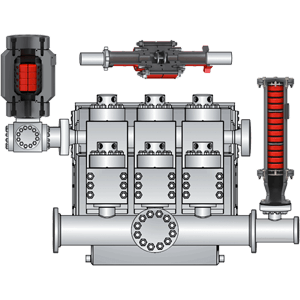
Mud pumps come in a variety of sizes and configurations but for the typical petroleum drilling rig, the triplex (three piston/plunger) mud pump is used. Duplex mud pumps (two piston/plungers) have generally been replaced by the triplex pump, but are still common in developing countries. Two later developments are the hex pump with six vertical pistons/plungers, and various quintuplexes with five horizontal piston/plungers. The advantages that these new pumps have over convention triplex pumps is a lower mud noise which assists with better measurement while drilling (MWD) and logging while drilling (LWD) decoding.
The fluid end produces the pumping process with valves, pistons, and liners. Because these components are high-wear items, modern pumps are designed to allow quick replacement of these parts.
To reduce severe vibration caused by the pumping process, these pumps incorporate both a suction and discharge pulsation dampener. These are connected to the inlet and outlet of the fluid end.
The power end converts the rotation of the drive shaft to the reciprocating motion of the pistons. In most cases a crosshead crank gear is used for this.
Displacement is calculated as discharged liters per minute. It is related to the drilling hole diameter and the return speed of drilling fluid from the bottom of the hole, i.e. the larger the diameter of drilling hole, the larger the desired displacement. The return speed of drilling fluid should wash away the debris and rock powder cut by the drill from the bottom of the hole in a timely manner, and reliably carry them to the earth"s surface. When drilling geological core, the speed is generally in range of 0.4 to 1.0 m^3/min.
The pressure of the pump depends on the depth of the drilling hole, the resistance of flushing fluid (drilling fluid) through the channel, as well as the nature of the conveying drilling fluid. The deeper the drilling hole and the greater the pipeline resistance, the higher the pressure needed.
With the changes of drilling hole diameter and depth, the displacement of the pump can be adjusted accordingly. In the mud pump mechanism, the gearbox or hydraulic motor is equipped to adjust its speed and displacement. In order to accurately measure the changes in pressure and displacement, a flow meter and pressure gauge are installed in the mud pump.
The construction department should have a special maintenance worker that is responsible for the maintenance and repair of the machine. Mud pumps and other mechanical equipment should be inspected and maintained on a scheduled and timely basis to find and address problems ahead of time, in order to avoid unscheduled shutdown. The worker should attend to the size of the sediment particles; if large particles are found, the mud pump parts should be checked frequently for wear, to see if they need to be repaired or replaced. The wearing parts for mud pumps include pump casing, bearings, impeller, piston, liner, etc. Advanced anti-wear measures should be adopted to increase the service life of the wearing parts, which can reduce the investment cost of the project, and improve production efficiency. At the same time, wearing parts and other mud pump parts should be repaired rather than replaced when possible.
Mud pump is one of the most critical equipment on the rig; therefore personnel on the rig must have good understanding about it. We’ve tried to find the good training about it but it is very difficult to find until we’ve seen this VDO training and it is a fantastic VDO training about the basic of mud pumps used in the oilfield. Total length of this VDO is about thirteen minutes and it is worth to watch it. You will learn about it so quickly. Additionally, we also add the full detailed transcripts which will acceleate the learning curve of learners.
Powerful mud pumps pick up mud from the suction tank and circulate the mud down hole, out the bit and back to the surface. Although rigs usually have two mud pumps and sometimes three or four, normally they use only one at a time. The others are mainly used as backup just in case one fails. Sometimes however the rig crew may compound the pumps, that is, they may use three or four pumps at the same time to move large volumes of mud when required.
Rigs use one of two types of mud pumps, Triplex pumps or Duplex pumps. Triplex pumps have three pistons that move back-and-forth in liners. Duplex pumps have two pistons move back and forth in liners.
Triplex pumps have many advantages they weight 30% less than a duplex of equal horsepower or kilowatts. The lighter weight parts are easier to handle and therefore easier to maintain. The other advantages include;
• One of the more important advantages of triplex over duplex pumps, is that they can move large volumes of mud at the higher pressure is required for modern deep hole drilling.
Triplex pumps are gradually phasing out duplex units. In a triplex pump, the pistons discharge mud only when they move forward in the liner. Then, when they moved back they draw in mud on the same side of the piston. Because of this, they are also called “single acting.” Single acting triplex pumps, pump mud at a relatively high speeds. Input horsepower ranges from 220 to 2200 or 164 to 1641 kW. Large pumps can pump over 1100 gallons per minute, over 4000 L per minute. Some big pumps have a maximum rated pressure of over 7000 psi over 50,000 kPa with 5 inch/127 mm liners.
Here is a schematic of a triplex pump. It has three pistons each moving in its own liner. It also has three intake valves and three discharge valves. It also has a pulsation dampener in the discharge line.
Look at the piston at left, it has just completed pushing mud out of the liner through the open discharge valve. The piston is at its maximum point of forward travel. The other two pistons are at other positions in their travel and are also pumping mud. But for now, concentrate on the left one to understand how the pump works. The left piston has completed its backstroke drawing in mud through the open intake valve. As the piston moved back it instead of the intake valve off its seat and drew mud in. A strong spring holds the discharge above closed. The left piston has moved forward pushing mud through the now open discharge valve. A strong spring holds the intake valve closed. They left piston has completed its forward stroke they form the length of the liner completely discharging the mud from it. All three pistons work together to keep a continuous flow of mud coming into and out of the pump.
Crewmembers can change the liners and pistons. Not only can they replace worn out ones, they can also install different sizes. Generally they use large liners and pistons when the pump needs to move large volumes of mud at relatively low pressure. They use a small liners and pistons when the pump needs to move smaller volumes of mud at a relatively high pressure.
In a duplex pump, pistons discharge mud on one side of the piston and at the same time, take in mud on the other side. Notice the top piston and the liner. As the piston moves forward, it discharges mud on one side as it draws in mud on the other then as it moves back, it discharges mud on the other side and draws in mud on the side it at had earlier discharge it. Duplex pumps are therefore double acting.
Double acting pumps move more mud on a single stroke than a triplex. However, because of they are double acting they have a seal around the piston rod. This seal keeps them from moving as fast as a triplex. Input horsepower ranges from 190 to 1790 hp or from 142 to 1335 kW. The largest pumps maximum rated working pressure is about 5000 psi, almost 35,000 kPa with 6 inch/152 mm linings.
A mud pump has a fluid end, our end and intake and the discharge valves. The fluid end of the pump contains the pistons with liners which take in or discharge the fluid or mud. The pump pistons draw in mud through the intake valves and push mud out through the discharge valves.
The power end houses the large crankshaft and gear assembly that moves the piston assemblies on the fluid end. Pumps are powered by a pump motor. Large modern diesel/electric rigs use powerful electric motors to drive the pump. Mechanical rigs use chain drives or power bands (belts) from the rig’s engines and compounds to drive the pump.
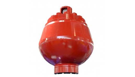
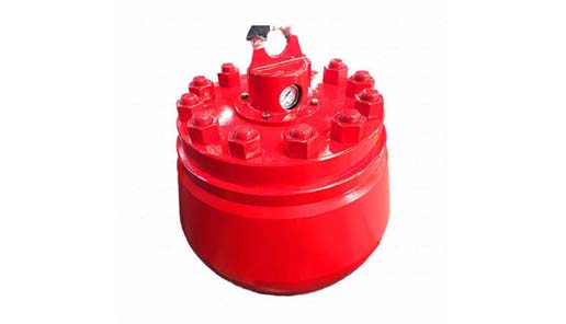
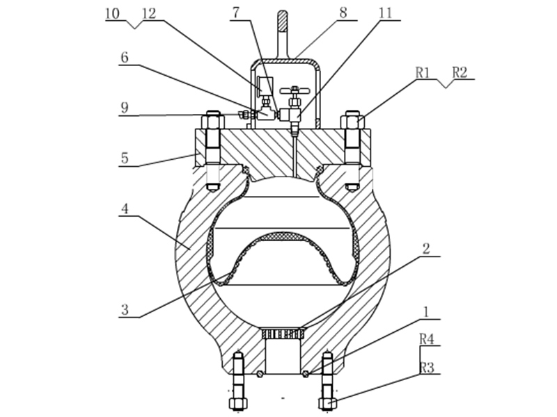
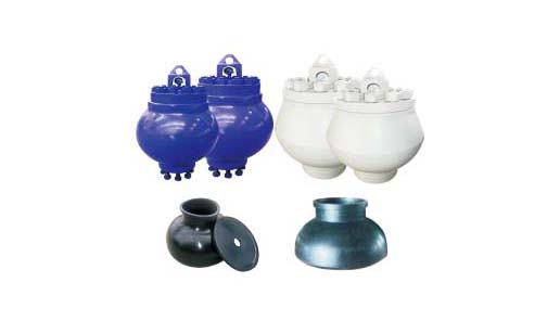
A pulsation dampener connected to the pump’s discharge line smooths out surges created by the pistons as they discharge mud. This is a standard bladder type dampener. The bladder and the dampener body, separates pressurized nitrogen gas above from mud below. The bladder is made from synthetic rubber and is flexible. When mud discharge pressure presses against the bottom of the bladder, nitrogen pressure above the bladder resists it. This resistance smoothes out the surges of mud leaving the pump.
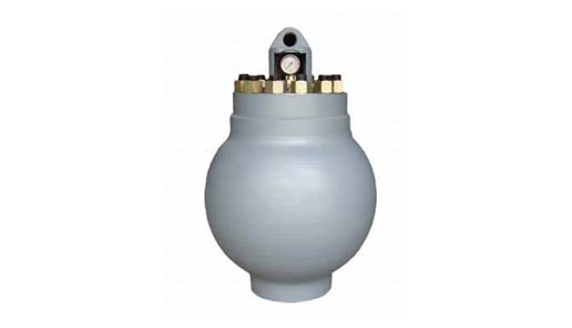
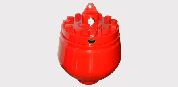
Here is the latest type of pulsation dampener, it does not have a bladder. It is a sphere about 4 feet or 1.2 m in diameter. It is built into the mud pump’s discharge line. The large chamber is form of mud. It has no moving parts so it does not need maintenance. The mud in the large volume sphere, absorbs this surges of mud leaving the pump.
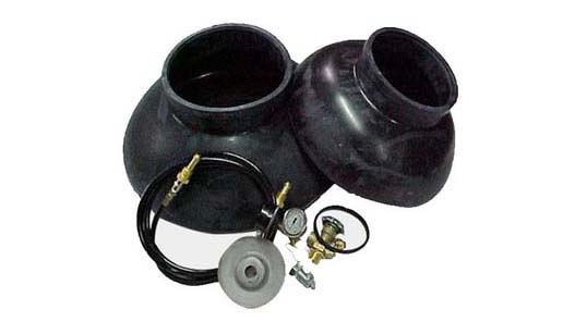
A suction dampener smooths out the flow of mud entering into the pump. Crewmembers mount it on the triplex mud pump’s suction line. Inside the steel chamber is a air charged rubber bladder or diaphragm. The crew charges of the bladder about 10 to 15 psi/50 to 100 kPa. The suction dampener absorbs surges in the mud pump’s suction line caused by the fast-moving pump pistons. The pistons, constantly starts and stops the mud’s flow through the pump. At the other end of the charging line a suction pumps sends a smooth flow of mud to the pump’s intake. When the smooth flow meets the surging flow, the impact is absorbed by the dampener.
Workers always install a discharge pressure relief valve. They install it on the pump’s discharge side in or near the discharge line. If for some reason too much pressure builds up in the discharge line, perhaps the drill bit or annulus gets plugged, the relief valve opens. That opened above protects the mud pump and system damage from over pressure.
Some rig owners install a suction line relief valve. They install it on top of the suction line near the suction dampener. They mount it on top so that it won’t clog up with mud when the system is shut down. A suction relief valve protects the charging pump and the suction line dampener. A suction relief valve usually has a 2 inch or 50 mm seat opening. The installer normally adjusts it to 70 psi or 500 kPa relieving pressure. If both the suction and the discharged valves failed on the same side of the pump, high back flow or a pressure surge would occur. The high backflow could damage the charging pump or the suction line dampener. The discharge line is a high-pressure line through which the pump moves mud. From the discharge line, the mud goes through the stand pipe and rotary hose to the drill string equipment.
Pump Pulsation Dampeners serve an important role of reducing excessive vibration and movement that is commonly characteristic of positive displacement pump systems. Pulsation dampeners absorb the energy coming from the positive displacement pump’s pulse waves. The pulsation dampener’s membrane contains compressible gas which creates the pneumatic damping cushion. This then allows for even flow downstream.
Our custom-designed systems will absorb excess energy pulsing through the pump and piping system by creating a low-pressure area to dampen the excess shocks and vibrations. Because a pulsation dampener regulates the release of energy, your system will be better protected and run more smoothly. After installing a pulsation dampener, customers notice that their system:
When you choose to work with our team, we’ll help you find the right specifications across our product series, allowing us to customize features, including:

Reciprocating pumps emit pulsations into the attached piping systems causing potentially dangerous unbalanced shaking forces, poor valve dynamics, high maintenance costs, and reduced flow. It is well known that gas charged elastomeric bladder or diaphragm pulsation dampeners can be used to effectively reduce the risks of these pulsation induced problems. Gas charged dampeners are relatively compact in size, and are easy to install when compared with maintenance free liquid filled options which tend to be large and more expensive to fabricate.
The potential for the dampener itself to become a vibration problem due to its branch connection being a heavy cantilevered mass having low mechanical natural frequencies.
These drawbacks are common issues for many operators. In a recent brownfield upgrade pump installation, Shell requested that the new pumps include a monitoring system to indicate when the gas charged dampener has failed. Beta Machinery (Beta) were contracted to include this study with the pulsation analysis being performed as per API 674. The hypothesis of the monitoring study was simple: when the dampener fails pulsations increase, an alarm is then triggered indicating a dampener failure.
The test of this hypothesis is presented in the following two-part case study of a brownfield upgrade. In the first part, we will provide the background of the oil company’s experience and the pulsation system model piping design. In next month’s installment, we will examine the complications that arise in a real installation and the challenges to overcome with variable speed pump operation.
Shell’s experience includes numerous reciprocating pumps for glycol and hydrocarbon condensate duties on both manned and unmanned offshore platforms. A majority of the older installations have reciprocating pumps equipped with bladder type pulsation dampeners. There have been numerous technical integrity issues related with the pulsation dampener losing pre-charge frequently, cases with the bladder material rupturing prematurely, and many cases of a notable increase in the vibration of the pump pipework leading to a failure and loss of containment.
With no form of indication available to ascertain the pre-charge pressure, it is difficult if not impossible to determine if the bladder, and/or bladder pressure is intact and holding. The only way to tell if the pulsation dampener is not performing as intended and has lost pre-charge is visual inspection of pipework. When the dampener has lost its pre-charge, the pipe work rattling and high vibration indicates some flaw in the working of the dampener. Under these circumstances the equipment has to be shutdown to manually inspect the dampener, as this has a direct impact on the reliability and downtime of the equipment.
The reciprocating pumps at the Shell Operating Unit facility are not equipped with on-line condition monitoring and the maintenance philosophy revolves around periodic off-line vibration condition monitoring typically carried out using a hand held instrument at three monthly intervals. For unmanned platforms the increase in vibrations are detected when the pump pipework vibration has increased substantially due to loss of pre-charge or the bladder giving away, presenting a high risk threat for operations.
The bladder in the dampener is very sensitive to changes in gas volume. As the line pressure changes, the volume of gas in the bladder changes, thus altering the system performance. The effectiveness of the pulsation dampeners can be reduced by bladder stiffness, bladder permeability, restriction of bladder expansion and contraction by dampener internals and degradation of performance due to large variations in line pressure, making the prediction of dampener performance complicated.
Technical integrity issues with the bladder material rupturing prematurely also surface when technicians charge the pulsation dampeners too quickly, leading to low temperatures at the elastomer interface and cracks propagating through the material. This has the effect of ultimately causing premature failure of the bladder material within a few charges.
Loss of containment through excessive pipe vibration and dampener failure, and the resulting impact on reliability statistics provided the motivation to address some of the issues described above. An opportunity to monitor the technical integrity of pulsation dampeners arose through brownfield project of F13 condensate transfer pumps (Triplex –double diaphragm type) to be installed on the existing E11 PB platform.
In order to address the pulsation dampener integrity issues, a change in the type of dampener from bladder type to the acoustic liquid filled type was considered. This approach was successful only on the greenfield projects. For the brownfield applications this approach met with a limited success considering the fact that space and cost of the liquid filled dampener is much higher than an equivalent gas filled dampener.
The existing piping arrangement is often congested, particularly for offshore facilities, hence the option of installing a liquid filled dampener is effectively ruled out. Moreover most of the pumps within the facility are slow speed with low frequency. Thus this approach was not effective in resolving the brownfield installations.
Metallic bellows type dampeners were next considered for cases where the bladder failed prematurely or failed to hold the pre-charge with the elastomeric element slipping off. This approach did provide some amount of success especially with the high temperature glycol service where the fluid temperature is around 248 degrees Fahrenheit (120 degrees Celsius). The high temperature for the glycol service led to the premature failures of the bladder elastomeric element and cases where the bladder lost its pre-charge within a few days of operation.
Manufacturers of pulsation dampeners were requested to provide some form of indication on the pulsation dampener for ascertaining the pre-charge of nitrogen. Some of the pulsation dampeners complied with this requirement by providing a T-connection with one end of the T connected to a pressure gauge. However, such indication is purely local and is of value only at manned platforms. For the unmanned platforms the issue of pre-charge pressure uncertainty remained.
With appropriate signal conditioning, accelerometers could be used to measure the low frequency and high frequency vibration. Accelerometers mounted on the pump manifolds serve this purpose. The acceleration data can then be used to identify issues with plungers/control rods or valves. However, vibration on the pump piping is generally due to the unbalanced forces in the piping from pulsation, as such measuring vibration would be an indirect method of gauging pulsation. So why not measure pulsation directly?
Based on the limited success with the above approaches, Beta was engaged to work with a manufacturer to provide a solution for triplex pumps to be installed on an unmanned facility. The objective of this exercise was to design an effective and well controlled pulsation system, and at the same time develop a monitoring system capable of detecting the condition of pulsation dampeners and alert operations for any abnormal behavior in the system. It is also to provide some form of assurance to predict the behavior of the dampeners under dynamic variations in the system pressure. F13 condensate transfer pumps were the subject of this approach.
In the second part of this analysis, we will illustrate that the difficulty and risk in maintaining a safe pump system with these dampeners is magnified in offshore and unmanned equipment operations.
Until better options appear on the market to address these important issues, pulsation monitoring is a technique that can be used to monitor dampener integrity. ■
Jordan Grose is the manager of pump systems for Beta Machinery Analysis. Ravindra Pai is a senior rotating engineer at Shell. For more information, visit www.betamachinery.com. This data was presented in an altered form at Dusseldorf’s International Rotating Equipment Conference in 2012.
Process pulsations can be reduced by adding a pulsation dampening device downstream of the pump. Equilibar engineers have leveraged their fluid control knowledge to design a pulsation dampener for single use bioprocessing systems.
This unique, non-restrictive device reduces system flow and pressure pulsations using a Class VI polymer single-use hollow body between two integrated diaphragms that face process pressure. The polymer body is enclosed in a permanent stainless steel housing with wing nut closure for easy change-outs.
The Equilibar® single use pulsation dampener uses pneumatics and self-adjusts its setpoint to match system pressure real-time to dampen pulsations. This behavior is similar to how the Equilibar SDO back pressure valve dampens pulsations, but is optimized for this dedicated dampening device.
The non-wetted sides of the diaphragms are pressurized using a pressure regulator connected to a port on the top and bottom of the stainless steel housing. This patented system will adjust its internal pressure in response to the force and direction of each pump pulsation against the diaphragms, reducing pulsation amplitude. Early trials have shown >70% reduction on amplitude, and establishes a more uniform pressure profile.
This dampening device, when compared to other single use dampeners, actively responds to pulsations which improves dampening capabilities compared with passive dampening devices. Furthermore, it’s compact size significantly reduces footprint, which makes it much easier to integrate. The Equilibar pulsation dampener has optimal performance in any orientation.
Upstream of single use flow meters – some flow meters experience a deterioration in accuracy when flow is unstable. A dampener upstream helps manage pressure disturbances to maintain accuracy.

This website is using a security service to protect itself from online attacks. The action you just performed triggered the security solution. There are several actions that could trigger this block including submitting a certain word or phrase, a SQL command or malformed data.


 8613371530291