
12 p 160 triplex mud pump manual free sample
This document contains proprietary and confidential information which belongs to National Oilwell; it is loaned for limited purposes only and remains the property of National Oilwell. Reproduction, in whole or in part; or use of this design or distribution of this information to others is not permitted without the express written consent of National Oilwell. This document is to be returned to National Oilwell upon request and in any event upon completion of the use for which it was loaned. National Oilwell DOCUMENT NUMBER
TABLE OF CONTENTS12-P-160 TRIPLEX MUD PUMP WITH FORGED CRANKSHAFTPAGE 1 2 3 4 5 6 7 8 9 10 11 DRAWING NO. PL 1292900-001 PL 1292901 PL 1292119 PL 1292902 PL 1292903 PL 1292120 PL 1292290 PL 1292225 PL 1292369 PL 1292125 PL 1292004 REV. A B DRAWING DESCRIPTION 12-P-160 TRIPLEX MUD PUMP COMPLETE POWER END COMPLETE PINION SHAFT SUB-ASSEMBLY FORGED CRANKSHAFT AND GEAR ASSEMBLY FORGED CRANKSHAFT AND GEAR SUB-ASSY. LINER SPRAY SYSTEM LINER FLUSHING SYSTEM STRAINER CROSS ASSEMBLY SUCTION STABILIZER HOIST COMPLETE OUTLINE DRAWING
This website is using a security service to protect itself from online attacks. The action you just performed triggered the security solution. There are several actions that could trigger this block including submitting a certain word or phrase, a SQL command or malformed data.

This website is using a security service to protect itself from online attacks. The action you just performed triggered the security solution. There are several actions that could trigger this block including submitting a certain word or phrase, a SQL command or malformed data.

NOV 12-P-160 Mud Pump is rated at 1600 input horsepower (1193 kw) at 120 strokes per minute, with a 12-inch (304.8 mm) stroke. Multiple liner sizes allow pressures and volumes to handle circulation requirements in deep drilling applications.
Flexibility: Compact engineering provides higher efficiency in less space. The NOV 12-P-160 Triplex Mud Pump light weight and flexible design make it easily adaptable to a variety of rig configurations. This provides flexibility as drilling requirements and conditions change.
Fluid End Modules: NOV offers a choice of fluid end modules and valve covers for every P Series pump model to select the fluid end module that exactly matches drilling requirements. All pump models can be equipped with either the standard or premium forged, two-piece interchangeable fluid modules

Since the NOV A1700-PT Triplex Mud Pump was built approximately 60 years ago, the industry has widely accepted the three cylinder or triplex style pump. Triplex mud pumps are manufactured worldwide, and many companies have emulated the original design and developed an improved form of the triplex pump in the past decade.
NOV A1700-PT Triplex Mud Pumps have many advantages they weight 30% less than a duplex of equal horsepower or kilowatts. The lighter weight parts are easier to handle and therefore easier to maintain. The other advantages include;They cost less to operate
One of the more important advantages of triplex over duplex pumps, is that they can move large volumes of mud at the higher pressure is required for modern deep hole drilling.
NOV A1700-PT Triplex Mud Pump is gradually phasing out duplex units. In a triplex pump, the pistons discharge mud only when they move forward in the liner. Then, when they moved back they draw in mud on the same side of the piston. Because of this, they are also called “single acting.” Single acting triplex pumps, pump mud at a relatively high speeds. NOV A1700-PT Triplex Mud Pump has three pistons each moving in its own liner. It also has three intake valves and three discharge valves. It also has a pulsation dampener in the discharge line.

Scomi Oiltools is in no way affliated with any company listed in this catalogue other than Scomi Oiltools. Reference to company names and company part
“DU” Slips . . . . . . . . . . . . . . . . . . . . . . . . . . . . . . . . . . . . . . . . . . . . . . . . . . . . . . . . . . . . . . . . . . . . . . . . . .3
“SD” Slips . . . . . . . . . . . . . . . . . . . . . . . . . . . . . . . . . . . . . . . . . . . . . . . . . . . . . . . . . . . . . . . . . . . . . . . . . .5
“C1” Slips . . . . . . . . . . . . . . . . . . . . . . . . . . . . . . . . . . . . . . . . . . . . . . . . . . . . . . . . . . . . . . . . . . . . . . . . . .9
“DCS” Slips . . . . . . . . . . . . . . . . . . . . . . . . . . . . . . . . . . . . . . . . . . . . . . . . . . . . . . . . . . . . . . . . . . . . . . . .11
“UC-3” Slips . . . . . . . . . . . . . . . . . . . . . . . . . . . . . . . . . . . . . . . . . . . . . . . . . . . . . . . . . . . . . . . . . . . . . . .13
“CMSXL” Slips . . . . . . . . . . . . . . . . . . . . . . . . . . . . . . . . . . . . . . . . . . . . . . . . . . . . . . . . . . . . . . . . . . . . .15
“LYT” Parts Only . . . . . . . . . . . . . . . . . . . . . . . . . . . . . . . . . . . . . . . . . . . . . . . . . . . . . . . . . . . . . . . . . . .17
API Bowls . . . . . . . . . . . . . . . . . . . . . . . . . . . . . . . . . . . . . . . . . . . . . . . . . . . . . . . . . . . . . . . . . . . . . . . . .43
Dual Spider . . . . . . . . . . . . . . . . . . . . . . . . . . . . . . . . . . . . . . . . . . . . . . . . . . . . . . . . . . . . . . . . . . . . . . . .44
Air Spider . . . . . . . . . . . . . . . . . . . . . . . . . . . . . . . . . . . . . . . . . . . . . . . . . . . . . . . . . . . . . . . . . . . . . . . . .45
“C” Safety Clamp . . . . . . . . . . . . . . . . . . . . . . . . . . . . . . . . . . . . . . . . . . . . . . . . . . . . . . . . . . . . . . . . . . .53
“T” Safety Clamp . . . . . . . . . . . . . . . . . . . . . . . . . . . . . . . . . . . . . . . . . . . . . . . . . . . . . . . . . . . . . . . . . . .55
“27-HPD & HSD” . . . . . . . . . . . . . . . . . . . . . . . . . . . . . . . . . . . . . . . . . . . . . . . . . . . . . . . . . . . . . . . . . . .63
Casing Scrapers . . . . . . . . . . . . . . . . . . . . . . . . . . . . . . . . . . . . . . . . . . . . . . . . . . . . . . . . . . . . . . . . . . .67

This document contains proprietary and confidential information which belongs to National-Oilwell Varco, L.P., its affiliates or subsidiaries (all collectively referred to hereinafter as "NOV"). It is loaned for limited purposes only and remains the property of NOV. Reproduction, in whole or in part, or use of this design or distribution of this information to others is not permitted without the express written consent of NOV. This document is to be returned to NOV upon request and in any event upon completion of the use for which it was loaned. This document and the information contained and represented herein is the copyrighted property of NOV. National Oilwell Varco
6 PRESERVATION PROCEDURE WHEN STORAGE EXCEEDS SIX (6) MONTHS OF INITIAL PRESERVATION. .......................................................................................................... 6 7
SCOPE This specification covers the preservation and storage procedure for shipment of new-build NOV Triplex Mud Pumps shipped from the manufacturing plant. This specification is intended to provide preservation of new-build NOV Triplex Mud Pumps for six (6) months from the shipment of the mud pump from the manufacturing facility. If a pump is to be stored for a period of time exceeding six (6) months, additional precautions should be taken as outlined in this specification. National Oilwell Varco recommends that all pumps are inspected for any signs of corrosion and for proper preservation at a minimum every three (3) months for pumps stored outside and every six (6) months for pumps stored indoors. Sub-tier: National Oilwell PS-3081
MANUFACTURING PLANT PRESERVATION PRIOR TO PAINT Drain all water and clean out liner wash tank. Remove drain plug in bottom of liner wash pump and drain water then reinstall plug. Remove discharge flange from liner wash pump and pour one (1) pint of inhibiting oil-based concentrate (Cortec VpCI 329 Vapor Corrosion Inhibiting oil-based concentrate or equivalent) into liner wash pump. Rotate two (2) revolutions by hand to distribute the product. Re-install discharge flange. Drain all oil from pump power end sump and remove crosshead covers and inspection covers. Clean out oil sump as per National Oilwell PS-3081 (Mud Pump Cleanliness). Spray all internal machined parts of power end and crosshead area with inhibiting oil-based concentrate (Cortec VpCI 329 Vapor Corrosion Inhibiting oil-based concentrate or equivalent). Rotate pump ½ turn and re-spray. Pour quantity of inhibiting oil-based concentrate specified in the table below into power end sump. Mud Pump Models
For pumps equipped with chain drives, spray internal machined parts inside chain cases with inhibiting oil-based concentrate (Cortec VpCI 329 Vapor Corrosion Inhibiting oil based concentrate or equivalent).
Replace all guards and seals as necessary using specified gasket material and sealing compounds. Remove fluid end valve covers, seals, valves springs and seats and treat internal cavities of fluid ends, discharge manifold, discharge strainer block and suction manifold with rust preventative (CRC SP400 or equivalent). Coat threads with anti-seize (KOPR KOTE 10002 or equivalent) and coat bottom side of valve cover with rust preventative. Reinstall seals and fluid end valves covers hand tight. Customer liners, pistons, piston rods, valves, seats, springs and liner retention parts are not used for plant testing. These expendables are checked for preservation when packed and then shipped with the loose parts.
MANUFACTURING PLANT PRESERVATION AFTER PAINT Remove breather and pack with loose parts for later shipment with pump. Seal breather hole with a greased solid plug. Affix a warning label near the breather opening (see Exhibit 1). Spray all external unpainted machined parts of pump with rust preventative (CRC SP400 or equivalent). Cover large diameter pipe and other openings with hardboard and protective plastic wrap. Liner bushing openings shall also be covered and sealed. Seal all other pipe work (air, water, and electrical) with plastic caps of the correct size and style. Electrical J-boxes are to be encased in protective plastic wrap. Place two (2) onepound bags of desiccant inside each J-box before sealing with tape. Wrap pressure gauges with bubble paper and plastic. Tape or band down loose hinged guards and inspection covers. Spray all machined unpainted loose parts and expendables to be shipped with pump with rust preventative (CRC SP400 or equivalent). All parts will be wrapped or boxed to prevent damage. Affix one (1) warning label (see Exhibit 2) to the power end pump cover and one (1) warning label on the fluid end assembly of the pump. Affix warning labels on each loose part container. In cases where the equipment will be boxed at an offsite export packer, a sufficient number of warning labels will be supplied with the shipment.
STORAGE AT MANUFACTURING PLANT OR FINAL DESTINATION Indoor storage is preferred whenever possible; but if outside storage is required, ensure pump is stored away from salt water spray, sand blast or other adverse conditions. It is highly recommended that ship loose parts be stored indoors to eliminate conditions that promote condensation and direct sources of moisture. It is also recommended to store pump on blocks and cover entire pump with plastic sheeting.
STORAGE PREPARATIONS FOR MAIN DRIVE MOTORS. For storage preparations for main drive motors, National Oilwell Varco recommends that the original manufacturer’s instructions be followed. If space heaters are supplied, the Jbox plastic wrap must be removed and the heaters should be connected throughout the complete storage period.
PRESERVATION PROCEDURE WHEN STORAGE EXCEEDS SIX (6) MONTHS OF INITIAL PRESERVATION. Note: It is recommended that inspections be carried out on six (6) month cycles when pumps are in indoors and three (3) month cycles when stored outside. Remove plastic sheeting. Remove side crosshead covers and top inspection covers and inspect for any internal corrosion. Correct any adverse conditions. Replenish rust inhibitor to quantities previously listed. Rotate pinion shaft five (5) revolutions using supplied tool. Inspect for condition of external protection (rust preventative and paint). adverse conditions.
START-UP AFTER STORAGE Any pump that has been in storage will need a thorough inspection prior to start-up to insure it has not been damaged in any way and that all parts are properly in place. Failure to observe the following points can result in serious damage. Before servicing the pump, the power end sump and chain drives housings will need to be drained of any inhibiting additive. The Cortec brand products used for preservation are compatible with all lubricating oils and need not be totally removed when putting equipment into service. To service the Power End after storage and prior to start-up, remove all covers and thoroughly clean and inspect all of the parts and finished surfaces. Check all of the bearings to make certain they are clean and in good condition. Fill the power end with clean EP oil of the proper viscosity to the proper level. Make sure oil is poured into the oil distribution trough and is worked into all of the bearings. Replace all covers and install breather. To service the Fluid End after storage and prior to start-up, remove covers and thoroughly clean and inspect inside of the fluid end cylinders. Properly install valves, pistons, liners and all other fluid end parts. Carefully tighten all bolts, nuts, studs and working connections to specified torque requirements.
Pre-Start Up Requirements..................................................................................... 1. Power End.................................................................................................. 2. Main Electric Drive Motors……………………………………………… 3. Auxiliary A/C Motors……………………………………………………. 4. Instrumentation........................................................................................... 5. Liner Wash System..................................................................................... 6. Fluid End.................................................................................................... 7. Suction Dampener/Desurger....................................................................... 8. Pulsation Dampener.................................................................................... 9. Pressure Gauge............................................................................................ 10. Reset Relief Valve....................................................................................... 11. Discharge Strainer………………………………………………………… 12. Mud Pump Drive Assembly………………………………………………. a. Belt Drive Units…………………………………………………… b. Chain Drive Units………………………………………………….
Part II. Commissioning Procedures 1. Pre-Commission Checks………………………………………………….. 2. Commissioning Operational Test…………………………………………. 3. Inspections/Check-Offs during Test Program……………………………..
INITIAL STARTUP PROCEDURES GENERAL: The initial startup procedures are written to assist the operator in preparing the pump packages for normal operation. The startup procedures are separated into two categories: Part I: Pre-Commissioning, and Part II: Commissioning Procedures. It is suggested that a copy of these pages be made for each pump to be used as a check-off sheet.
a. Drain and flush any moisture or contamination that has accumulated in the power end reservoir. Fill to the “FULL” mark on the dipstick with the recommended oil. Ambient Temperature: 0°F to 85°F (-18°C to 33°C) = 30°F to 155°F (-1°C to 68°C) =
Reservoir Capacity: 100 US Gallons (379 Liters) Note: The rust preventative on the internal surfaces of the pump is oil-soluble and is compatible with the lubricants recommended above. It is not necessary to flush and drain unless the preservative has become contaminated (water, sand etc.). b. Oil Filters: Assure that the oil filters in the power end reservoir and external oil pump system are clean. 2. Main Electric Drive Motors:
Megger test the motors. Check each motor separately for the correct rotation. Reconnect if necessary. Megger test the blower motors. Check blower motors for correct rotation and quantity of air flow.
Clean liner wash tank, if needed, and fill with fresh clean water. Ensure that supply hoses and spray nipples are installed correctly. Start pump and adjust regulating valve to maximum flow without splash onto the extension rods.
Check to assure that all liners, valves, and pistons are installed properly in accordance with the installation instructions. Ensure that the liner end covers are installed on the rear end of the liners. Ensure that the baffle discs are installed on the end of the crosshead extension rods. Clean grease and paint from the exposed parts of the extension rods, checking for burrs. Coat rods with a light oil.
NOTE: When charging the bladder, make sure that the mud pump suction line valve has been closed and that all pressure has been bled off of the suction manifold surrounding the suction desurger
If a dampener is used, charge dampener with a hand-operated air pump to 10 PSI (0.7 bar). Once pump operations have been started, check the operation of the suction dampener by inspecting the sight glass. Add or release air pressure through the Shraeder valve to keep the diaphragm between the midpoint and the bottom of the sight glass.
Check the installation and the setting. NO SHUT-OFF VALVE is to be between the pump discharge and the relief valve. Ensure that piping from the discharge port goes directly to the mud tank/pit and is securely tied down, with a minimum downward slope of 1/4” per foot. Ensure that piping has pressure rating equal to the relief valve highest setting.
Check the belt guards to ensure that belts will not drag on the guard. Check the belt tension as instructed in the maintenance section of the operations manual. Check the alignment of the drive motors.
Check the chain guards to ensure that the chains will not drag on the guard. Check the oil pump to ensure that the relief valve is installed on the suction side. Start the pump and ensure that the spray nozzles are spraying oil over the full width of the chain. Adjust the relief valve to 15-25 PSI output with the warm oil.
PART II. COMMISSIONING PROCEDURES: GENERAL: The power end and the fluid end have gone through rigorous tests prior to being shipped from the manufacturing site; therefore, the following recommendations for the commissioning test are made for the purpose of checking the overall unitization functions, including instrumentation, and to assure that there are no problems which may have occurred during transportation and storage. Operation of the pump in parallel to check the SCR-Motor assignments and controls, volumetric displacement and mudline systems are at the option of the purchaser. A. PRE-COMMISSIONING CHECKS: Prior to starting the unitized pump package, review the previously outlined Pre-Commissioning Requirements in Part I. Check the discharge mudline to assure that all necessary valves are open. Ensure that the mud tanks are full of test fluid (mud/water) prior to startup. Make the desired assignment of the SCR-Motor Control System to the pump motors, and open the throttle slightly. Check to ensure that charge pump and liner wash motors have started. If no immediate problems are encountered, slowly throttle the pump to approximately 60 SPM and continue operating the mud pump while making the following inspections to assure that all systems are working properly: 1) Power End Lubrication: Check oil pressure:
Adjust the regulator valve for proper volume of cooling fluid. 10 US Gallons (38 Liter) per minute per liner. Check the coolant temperature. 150°F (66°C) maximum.
5) Visually inspect the mud pump drive assembly for any unusual conditions, i.e. loose bolts, vibration, noise, etc. 6) Check the performance of the supercharging system:
Check the valve for proper relief setting. The valve should be set 10% above the pressure rating for the liner size being used. Refer to the nameplates on each side of the pump or the pump datasheet to obtain the operating pressure for that particular size liner.
B. COMMISSIONING OPERATIONAL TEST: DURATION: EIGHT (8) HOURS TOTAL RUNNING TIME. The following are basic guidelines for conducting of an eight (8) hour operational test. The pump was test run under pressure in the manufacturing plant but with different motors and drives. The discharge pressure can be regulated by temporarily installing an adjustable choke at some point in the discharge line. NOTE: There can be short intervals of shut-down time to fix leaks, make adjustments, etc., without having to restart the test program. 1. LOWER PRESSURE TEST – DURATION: TWO (2) HOURS: TIME START STOP 0-500 PSI (0.34-34.5 bar)…………………40 min. @ 40 SPM
C. INSPECTIONS/CHECK-OFFS DURING TEST PROGRAM: The overall performance of the unitized pump package should be continuously monitored during the eight hour test program. The following checks should be made and recorded each two hours of operation. START
This document contains proprietary and confidential information which belongs to National Oilwell Varco; it is loaned for limited purposes only and remains the property of National Oilwell Varco. Reproduction, in whole or in part; or use of this design or distribution of this information to others is not permitted without the express written consent of National Oilwell Varco. This document is to be returned to National Oilwell Varco upon request and in any event upon completion of the use for which it was loaned. © National Oilwell Varco
PREFACE This manual is provided for guidance of those who wish to install, repair, maintain, or adjust the National Oilwell Varco equipment covered herein. This information has been prepared with a basic viewpoint to give accurate and concise data needed to perform minor adjustments as well as major overhauls. This information is not elementary, as it is intended for operators and servicemen who are familiar with drilling equipment in general. It is not intended, nor would it be possible in such limited space, to cover every possible condition which may be encountered. Always use good, sound mechanical practices and safety precautions. All specifications are in accordance with Engineering designs and should be adhered to in all repairs. Operation and maintenance information on equipment other than National Oilwell Varco’s is taken in part from the various manufacturers’ manuals. If the equipment manufacturers issue later instructions, or in the event of conflict, the manufacturer’s information will take precedence over that shown in this manual, unless specifically stated otherwise. Refer to the General Lubrication Bulletin for approved lubricants. If any discrepancy exists between the recommendations in this manual and the General Lubrication Bulletin, those in the Lubrication Bulletin will take precedence. The manual sections follow logical divisions in major components, and cover all standard production unless otherwise specified. Specifications and components covered are for standard equipment current at the time this manual was approved for printing. National Oilwell Varco reserves the right to discontinue models at any time, or change specifications or design of any model without notice and without incurring any obligation.
IN ORDER TO PREVENT PERSONAL INJURY during performance of any maintenance or inspection procedures, this equipment must be shut down and not operating. Each motor and generator is equipped with a motor cutout switch. This switch should be IN, and the safety bar in place, when any maintenance or inspection procedures are performed. Employ good mechanical practices when making maintenance repairs, adjustments, inspections, etc.
When operating all mechanical and electrical equipment, all safety devices must be engaged, properly adjusted, and in good operating condition, including overtravel devices for traveling blocks, warning or shutdown devices for engines, etc.
TABLE OF CONTENTS PREFACE.................................................................................................................................... 3 1
INSTALLATION OF NEW PUMP Your National Oilwell Varco pump has been completely assembled and test operated under pressure before being shipped to the field. Unless otherwise instructed, the lubrication is drained from the power end and the expendable parts are removed from the fluid end. Before putting the pump into service, the following precautions and operations must be performed or checked. In order to prevent personal injury during the performance of any maintenance or inspection procedures, this equipment MUST BE SHUT DOWN AND NOT OPERATING, and all safety devices on prime movers, drives, etc., MUST BE IN THE SAFE POSITION.
SETTING THE PUMP The skids under the National Oilwell Varco pumps are suitable for most any type of installation. It should be noted, however, that the box type construction of the power frame has high resistance to bending but relatively less resistance against twist. Therefore, the support under the pump must be level and adequate to support the weight and operating forces exerted by the pump.
Land Installations In land installations, a mat of 3” X 12” (76.20 mm x 304.8 mm) boards laid side crosswise to the pump skids for the entire length, or at a minimum, at the points indicated in Fig. 2, is usually sufficient. The boards should be a few feet wider than the width of the pump skid runners. Wet or marshy locations may require a more stable foundation.
Fig. 2 Suitable means, such as National Oilwell Varco pump spacers as shown in Fig. 3, should be used to keep the pump anchored and the drive in alignment. National Oilwell Varco mud pump spacers provide 8-1/2” (215.9mm) adjustment. Any desired length may be obtained by lengthening the standard pipe spacer, which is made of 3” (76.20mm) extra strong pipe. Three types of attaching heads are available with this spacer:
2.1.1 Permanent Installations On permanent installations such as barge, platform, structural base, or concrete slab, where pump skids are bolted down, it is essential that the skids be properly shimmed to prevent possibility of twisting or distorting the power frame. The pump skids must sit solid on all shim points with bolts loose. On barge installations, the pump skids are generally bolted down to T-beams running parallel and in line with the pump skids. Install shims at points shown in Figs. 2 and 4 and observe caution of proper shimming to prevent twist or distortion. The shims on all installations should extend the full width of the skid beam flanges and have a minimum length of 12” (305mm). On installations where the power unit or electric motor is mounted integrally with the pump skids, the preferred installation would be to set the pump package on the T-beam skids and provide retention blocks rather than bolts to hold it in place. This will allow the pump to “float” and minimize the transfer of barge deck or platform distortion into the frame. 2.1.2 Installation of the Drive The drive between the mud pumps and the power source, whether V-belts or multi-width chains, should be installed with the greatest care to assure maximum operating life with minimum of unexpected or undesirable shutdowns due to drive failures. When installing the drive sheave or sprocket, make sure all grease or rust preventative is removed from the shaft and the bore of the drive. Remove all burrs or rough spots from the shaft, key, and keyway. Fit key to the keyways in both the shaft and drive and install key into shaft keyway. Coat pinion shaft with a light coating of anti-seize compound or light oil and install the drive sheave or sprocket hub. Tighten hub bolts as indicated below:
When a wrench or length of pipe is used to increase leverage in tightening draw-up bolts, it is imperative to adhere to the wrench torque values given in the chart below. This adherence is important, because in mounting the hub, the tightening force on the bolts is multiplied many times by the wedging action of the tapered surface. This action compresses the hub for a snug fit on the shaft. If the bolt tightening forces are extreme, bursting pressure is created in the hub of the mounted pulley; this pressure may cause the pulley to crack. The hub bolts should always be tightened alternately and progressively.
2.1.2.1 V-Belt Drives a. Check sheave groove condition. Before installing the V-belts, check sheave grooves for wear. Worn or rounded grooves will destroy V-belts rapidly. The side walls must be straight. Sheave grooves must be free of dirt, rust or other extrusions which could damage the Vbelts. b.
Check sheave alignment. The final alignment of the V-belt sheaves should be checked after the V-belts have been installed and adjusted to their operating tension. If the sides of the sheaves are of equal distance from the centerline of the groove, check alignment by stretching TWO strings (fish line or piano wire preferred) along one side of the two sheaves, one above and one below the centerline, and moving one of the sheaves until the strings touch four points on the side of the sheave rims. This will determine that the centerline of the drives are parallel and the faces of the sheaves are square.
Adjust V-belts for proper tension. Adjust the belt tension by moving the sheaves apart until all of the sag has just been eliminated from the tight side of the belt and some of the belts on the slack side. Then increase the centers approximately ½” (13mm) for each 100” (2540 mm) center distance. Example: On 150” (3810 mm) center, move pump an additional ¾” (19.5 mm).
DO NOT OBTAIN BELT TENSION BY PICKING UP END OF PUMP AND ALLOWING BELTS TO TIGHTEN UNDER WEIGHT OF PUMP AS END IS BEING LOWERED TO THE GROUND. 2.1.2.2 Chain Drives a. Installation Proper installation and maintenance of the sprocket and chain drives are essential if good service life is to be obtained. Since many factors, such as chain width, center distances, speeds, and loads must be considered when determining the allowable tolerance for sprocket alignment, no good “rule of thumb” can be applied. The chain alignment must simply be held as nearly perfect as possible. A more precise alignment can be made by stretching two steel wires (piano wire) along one face of the two sprockets, one above and one below the centerline, and moving one of the sprockets until the wires touch at four points. This will determine that the centerlines of the drives are parallel and the faces of the sprockets are square. b.
Drive chain lubrication The pump drive chain lubrication system on the majority of National Oilwell Varco pumps is an independent system having its own oil pump, reservoir, and drive. Fill chain case to the indicated level with a non-detergent oil as follows: Ambient temperature above 32°F (0°C) SAE-30 Ambient temperature below 32°F (0°C) SAE-20 For temperatures below 0°F, consult a reputable lubrication dealer for recommendations. REFER TO GENERAL LUBRICATION BULLETIN for approved lubricants and additional specifications. If any discrepancy exists between the recommendations in this manual and the General Lubrication Bullletin, those in the Lubrication Bulletin will take precedence. Since this is an independent system, it will require the same maintenance or service attention employed on any other piece of machinery, including: - Daily check of oil level. - Daily check on condition of oil. - Frequent check on oil pressure. (5-15 psi) (.352 - 1.06 kg/cm²) - Volume of oil being applied to chain. - Condition of nozzles in spray tube. - Condition of oil pump drive (V-belts or chain)
NOTE: Oil pressure may be adjusted with the pressure relief adjusting screw on the rear of the pump housing. Pressure drops may also indicate suction and discharge filter screens need cleaning. 3
SUCTION SYSTEM REQUIREMENTS Individual installation conditions will dictate the design of the suction system. The suction of the FD-series pumps must have a positive head (pressure) for satisfactory performance. The optimum suction manifold pressure is 20-30 psi (1.75-2 kg/cm²) for maximum volumetric efficiency and expendable parts life. This head pressure is best supplied by a 5 x 6 centrifugal pump with 40 h.p. 1150 rpm electric motor. This type of drive requires a device to automatically start and stop the centrifugal pump motor simultaneously with the triplex pump. On DC electric powered rigs a signal can usually be supplied from the DC control panel to energize a magnetic starter when the mud pump clutch air line will provide a set of contacts for energizing the magnetic starter when clutch is engaged. The charging pump can also be belt driven from the triplex pinion shaft charging type of drive is not as efficient at slow speeds with viscous fluids. Under some conditions the FD-Series pumps may be operated without a charging pump, provided the fluid level in mud pits is higher than the top of the liners, fluid being pumped is low viscosity and suction line must be short, straight and of at least the same diameter as suction manifold inlet. The suction lines should be piped with valve arrangements so the charging pump can be by-passed so operation can be continued in event of charging pump failure or for maintenance. Operation without a charging pump can be improved by replacing the suction valve springs with a weaker spring. Suction desurgers are a very effective aid for complete filling of the liners and dampening pulsations in the suction line which results in a smoother flow in the discharge line. If your pump is equipped with a suction desurger it must be pre-charged with compressed air before operations are begun. See suction desurger manual for charging instructions.
Caution Do not pipe the return line from the shear relief valve back into the suction system as a relief valve operation will cause a sudden pressure rise in the system vastly greater than the system pressure ratings, resulting in damage to manifold, suction desurger and centrifugal pump.
PREPARATION OF POWER END Your National Oilwell Varco pump has been completely assembled and test operated before being shipped to the field. Unless otherwise instructed, the lubrication is drained from the power end, and the expendables are removed from the fluid end for storage protection. Before operating the pump, the following must be performed or checked:
Power End Lubrication Before installing lubricant, open inspection door in cover and check oil reservoir for possible accumulation of condensation, etc., and drain and flush by removing the pipe plugs on each side of the pump. Add the proper type and quantity of lubrication in the power end. Refer to the Lubrication Section of this manual, or lubrication plate on pump frame for type and quantity required. Recheck oil level after pump has operated for a period of 15 minutes. Shut pump down and allow approximately five minutes for the oil level to equalize. Check at oil level gauge, Item 1, Fig. 1. It is usually necessary for a few more gallons of oil to be added due to a certain amount being retained in the crosshead area and frame cavities.
With reference to Figure 5, remove the diaphragm stuffing box and plate (1) and rotate pump so that crosshead is at the front of the stroke. Thoroughly clean the front of the crosshead and the face of the crosshead extension rod. Insert alignment boss on crosshead extension rod into the crosshead bore and tighten the retainer bolts (2) to the following torque. Safety wire bolt heads. FD-500 50-60 ft. lbs. (7-8 meter kgs) FD-800 80-100 ft. lbs. (11-14mkgs.) FD-1000 350-370 ft. lbs. (48-51 meter kgs) FD-1600 350-370 ft. lbs. (48-51mkgs.) Thoroughly clean face of power frame and diaphragm stuffing box plate at Position “A”. Install gasket (3) and capscrews (10). Tighten capscrews as follows: FD-500 12-14 ft. lbs. (1.7 - 1.9 meter kgs)
Clean bore and face of diaphragm stuffing box plate. Clean OD and flange of diaphragm stuffing box. Coat OD of diaphragm stuffing box with light oil and install Oring seal (4). Insert diaphragm stuffing box in plate bore and tighten capscrews to the following torque: FD-500 12-14 ft. lbs. (1.7 - 1.9 meter kgs)
The diaphragm stuffing box packing assembly consists of a single lip oil seal (6), a double lip wiper seal (11), a separator spring (7), an O-ring (8), and a lock spring (9). Install the assembly as follows: a. Remove pressure spring (5) from single lip oil seal (6) and place seal in the inner (power end) position on the crosshead extension rod, with lip toward power end. Replace the pressure spring in the seal lip and slide the seal into position in the stuffing box. SEE NOTE BELOW. b. Insert the separator spring (7) over rod and slide it into stuffing box bore. c. Install the O-ring (8) in groove in stuffing box bore. d. Remove pressure spring (5) from double lip oil seal (11) and place seal in the outer position on the crosshead extension rod with main lip toward power end. Replace the pressure spring in the seal lip and slide the seal into position in the stuffing box. SEE NOTE BELOW. CAUTION:
The double lip seal can be used in the inner, or power end, position to replace the single lip seal, but DO NOT use the single lip seal in the outer position.
e. Install the lock spring (9). NOTE: CAUTION must be taken to assure the pressure spring (5) does not slip out of the groove in the oil seal lip, as severe scoring of the crosshead extension rod can occur. Coat extension rod with a light oil to facilitate installation of the packing assembly. 5
PISTON AND LINER COOLING SYSTEM Proper attention must be paid at all times to assure adequate cooling fluid is being applied to the piston and liner assembly. Stoppage of the cooling fluid will result in almost instant failure of the piston rubbers and possibly extensive damage to the liner bore.
Two types of piston and liner cooling systems have been used on National Oilwell Varco FD-Series Pumps -- the stationary spray type and a moving nozzle type. Ref. Fig. 6. The manifold (1) for supplying cooling fluid to the piston and liner assemblies is identical on both systems. Cooling fluid from either a remote source such as a water line, or from a pump and reservoir system unitized on the pump skids (Ref. Fig. 7) must be piped into the manifold at the connection located in the pump frame under the crosshead extension rod section. CAUTION:
The supply line from a remote system should be equipped with a strainer to prevent stoppage of the spray nozzles. Water should be cool and free of abrasive solids. Clean strainer screen or trap once each day, or as required.
Stationary spray (View A, Fig. 6) The stationary spray cooling system consists of a spray nozzle (2) mounted on a liner end cover plate (3), which applies cooling fluid in the form of a spray to the piston and liner area. Adjust cooling water supply to the manifold so that a spray approximately *12” long is being discharged from each spray nozzle. Inspect spray nozzle operation VERY OFTEN, making sure the nozzle is pointed directly at the piston. *(304.8mm)
Moving Nozzle The moving nozzle system consists of a spray tube (4) mounted on the extension rod clamp (5), which applies cooling fluid directly to the back face of the piston. The end of the spray tube is positioned approximately 1” from the back face of the piston, which causes the cooling fluid to be deflected so that it constantly floods the piston liner area throughout the full stroke length. Inspect spray tube very often to assure that ample cooling fluid is being supplied. At routine intervals, check condition of the hose (6) which connects the spray tube to the manifold. This hose travels back and forth with the piston rod assembly, therefore must be installed so that its movement is not restricted.
With reference to Fig. 7, maintain electric motor (1) and centrifugal pump (2) according to manufacturer’s specifications. Rotation of the pump should be clockwise when viewed from the impeller end. Adjust regulating valve (3) to apply as much water as possible to the liners without splashing back on the crosshead extension rods and diaphragm stuffing box plate. 10gallons per minute per liner is the preferred flow rate. If water is allowed to splash on the crosshead extension rods, some of the water may work back into the power end to contaminate the lubrication oil.
The cooling fluid is returned from the crosshead extension rod compartment to the settling chamber, and as the fluid overflows through the filter screen between the two sections of the tank, the solids are allowed to settle out. The filter screen will catch much of the foreign material floating in the fluid. Check condition of the cooling fluid at frequent intervals and CLEAN and FLUSH reservoir as required. Contaminated fluid will cause premature liner and piston wear from abrasion or stoppage of the spray nozzle or spray tube. 6
Valves and Seats Remove all three discharge valve pot covers (1), and three cylinder heads and plugs (2), and thoroughly clean all machined surfaces in the fluid end with a good cleaning solvent. Make sure all valve seat bores are VERY CLEAN AND DRY (free of dirt, grease, anti-rust compound, etc.) and remove all burrs or nicks with a fine emery cloth, using circular motion around seat surfaces.
THOROUGHLY CLEAN AND DRY the valve seats and install suction and discharge valve seats into the valve pot bores. Drive seats firmly into place with a bar and hammer. Install valves and springs, etc., by following any special instructions that may have been outlined by the specific valve and seat manufacturer. Install fluid baffle (11), fig. 9 and 9B on end of crosshead extension rod.
Liners Inspect liner bore again to make sure it is clean and free of foreign particles to assure metal to metal contact between the liner and fluid end. Foreign particles can cause the liner to make up in a “cocked” position resulting in premature wear on liners and pistons.
Piston Rod Clean piston and piston rod, making sure they are free of nicks and burrs. Install “O” ring seal (20) in groove in piston head. Slide piston head on rod while observing that “O” ring does not fall out of groove. Tighten piston rod nut (21) to 1200-1600 ft. lbs. (166-121 m/kgs.). Coat liner I.D. and piston O.D. with grease. Check ends of piston rod and extension rod to be sure they are clean and free of burrs. Insert piston rod through liner holding piston rod centered at the rear of the liner. Drive the piston into the liner with a driving tool or a piece of hardwood and sledge hammer. Use caution as the piston rod approaches the crosshead extension rod that the dowel on the end of the piston rod is not damaged. The piston rod must be supported and the dowel guided into the pilot bore.
Piston Rod Clamps The piston rod clamps are machined as one piece and then cut in half. The two pieces are stenciled with matching numbers on each half and have a chain link connecting them together. The two pieces with the same matching numbers should always be kept together as a set. Install the clamp around the rod end flanges with the water connection holes at top dead center. Tighten cap screws to the following torque values. FD-500-368 ft. lbs.
When rods and rod clamps are new a gap in excess of ½” (13 MM) could be present between the two halves of the clamp. This is satisfactory provided the faces of the rods are seating metal to metal. As wear occurs, the halves will pull closer together. Clamping action will be lost when a gap no longer exist. At this time clamps must be replaced.
Liner Cage and Lower Valve Guide Install rear liner seal (5) and push into position against liner shoulder. Slide liner cage (6) into fluid end, align one hole in the cage with lower valve pot bore. Set lower valve guide (8) over valve stem through lower hole in cage with the wings on the guide turned crosswise to the pump. Press down on the guide, compressing the valve spring (7) until the guide can be rotated ¼ turn and seat into place underneath the cage. Insert the lower valve guide locking clip (9) through the pad eyes on the lower valve guide and rotate clip to the right to lock the valve guide tight against the OD of the liner cage. It may sometimes be necessary to put more or less bend in the center of the clip to make it retain the guide tightly while the clip handle snaps into position on the right hand side.
Cylinder head Insert the outer seal (5) in the fluid end bore against the liner cage. Slide the cylinder head plug (10) into fluid end. Apply a liberal coat of grease to both mating thread surfaces of the cylinder head (2). Screw cylinder head in and tighten with wrench furnished with pump and sledge hammer. Fluid leakage through the weep hole will indicate a defective seal or loose cylinder head. DO NOT plug weep holes as this can result in severe damage to cylinder head threads, thread rings, etc., in event of a liner seal failure.
Discharge Valve Pot Covers Install discharge valve pot gasket (3) into bore, and after liberal application of grease or tool joint compound to the gasket and thread area, tighten the discharge valve pot covers into place, using a sledge hammer and bar.
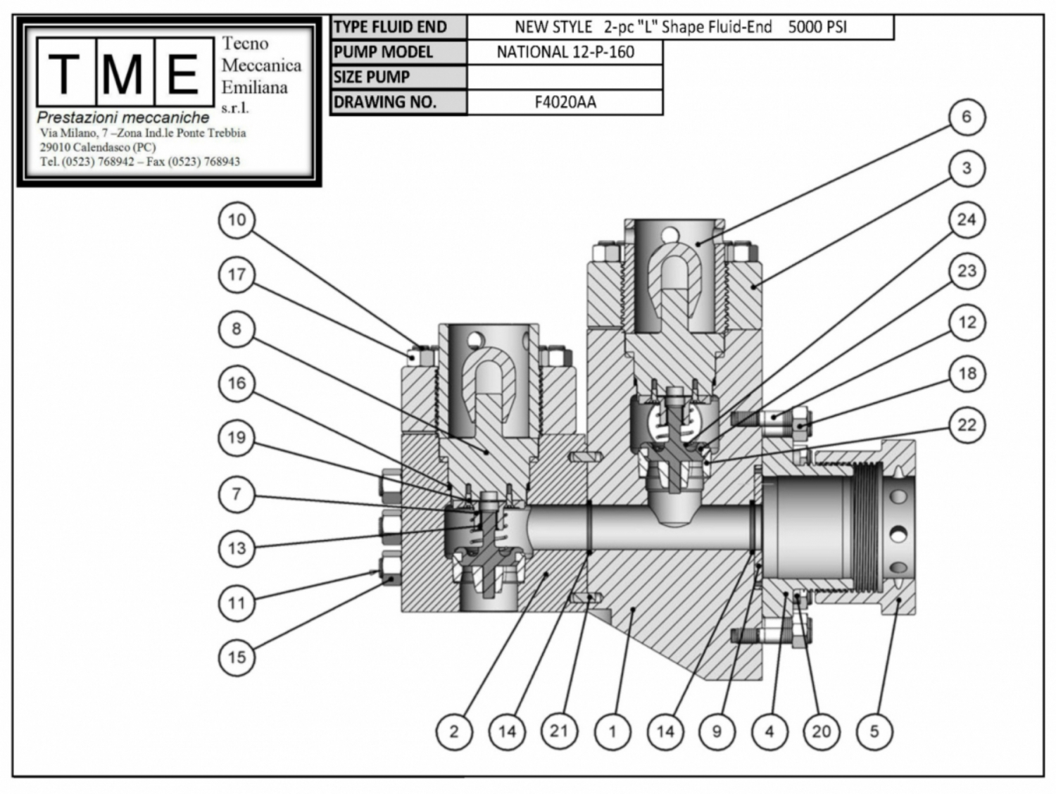
Figure 9B A cross section through the fluid end is shown in fig. 9B. With reference to fig. 9B thoroughly clean and assemble the fluid end parts in the following manner: Note: All of the parts in this fluid end assembly are designed with metal to metal seating to alleviate friction wear from breathing action encountered in modern high pressure pump operation. For this reason it is essential that all parts be clean and free of rust, nicks and burrs before being assembled.
Liner Install wear plate seal (1) in counterbore of fluid end. Slide wear plate (2) over studs until it seats against fluid end. Slide liner thread ring (3) over studs with the starting thread at the 5 o’clock position and tighten nuts to 470-510 ft. lbs. (65-70 m/kgs.) torque. Note: Placing the starting thread at 5 o’clock position makes engaging the liner lock threads much easier. Place liner seal (4) in counterbore of wear plate. Apply thin coat of grease to ID of liner lock (5) and slide over rear of liner (6). Install two-piece liner lock ring (7) in liner groove and “O” ring to hold them in position. Slide liner handling tool over liner up against liner lock ring and tighten set screw to secure it in place. Hoist liner assembly into position with jib hoist. Note: FD pumps are factory equipped with jib booms and liner handling tools. If older pumps are converted to FD fluid ends a jib boom should be added to the pump frame as considerable weight is involved in handling the liner assembly. Apply liberal coat of grease to liner lock threads. Align the starting thread of the liner lock (5) to the 7 o’clock position and insert the liner into the liner thread ring (3) screw liner lock in until liner seats in position . Tighten with sledge hammer on hammer lugs.
Piston Rod Clean piston (9) and piston rod (8), making sure they are free of nicks and burrs. Install “O” ring seal (10) in groove in piston head. Slide piston head on rod while observing that “O” ring does not fall out of groove. Tighten piston rod nut (11) to 1200-1600 ft. lbs. (166-121 m/kgs.). Coat liner I.D. and piston O.D. with grease. Check ends of piston rod and extension rod to be sure they are clean and free of burrs. Insert piston rod into liner through cylinder head opening holding piston rod centered at the rear of the liner. Drive the piston into the liner with a driving tool or a piece of hardwood and sledge hammer. Use caution as the piston rod approaches the crosshead extension rod that the dowel on the end of the piston rod is not damaged. The piston rod must be supported and the dowel guided into the pilot bore.
Piston Rod Clamps The piston rod clamps are machined as one piece and then sawed in half. The two pieces are stenciled with matching numbers on each half. The two pieces with the same matching numbers should always be kept together as a set. Install the clamp around the rod end flanges with the water connection holes at top dead center. Tighten cap screws to the following torque values: FD-1600
When rods and rod clamps are new a gap in excess of ½” (13 mm) could be present between the two halves of the clamp. This is satisfactory provided the faces of the rods are seating metal to metal. As wear occurs, the halves will pull closer together. Clamping action will be lost when a gap no longer exists. At this time clamps must be replaced. Install splash plate on rear of liner. 8.4
Lower Valve Guide and Cylinder Head Slide the alignment ring (12) into the cylinder head opening engaging the alignment dowel at the 3 o’clock position. Do not drive on this piece as dowel or dowel hole will be damaged. It will slide easily into place when it is properly aligned. Insert the lower valve guide (13) through the alignment ring and position the guide over the valve stem. Start the lock bolt (14) and draw it down, compressing the valve spring and seating the valve guide in the tapered slot. Tighten lock bolt to 300 to 340 ft. lbs. 41 to 47 m/kg². Install head seal (15) on cylinder head plug (16). Coat seal and O.D. of plug with light oil. Screw a 3 ft. (1 M) length of pipe into the threaded opening on the plug. Using the pipe to balance the plug, slide it straight into the fluid end opening. Apply a liberal coat of grease to the cylinder head (17) with wrench provided and sledge hammer. Fluid leakage through the weep hole will indicate a defective seal or loose cylinder head. DO NOT plug weep hole as this can result in severe damage to cylinder head threads, thread rings, etc., in event of a liner seal failure.
Discharge Valve Pot Covers Install discharge valve pot gasket (18) into bore, and after liberal application of grease or tool joint compound to the gasket and thread area, tighten the discharge valve pot covers (19) into place, using a sledge hammer and bar.
Discharge Manifold all models A 5”-1500*RTJ flange connection is provided on the discharge manifold. REMOVE flange and protect gasket area before welding (customer’s option) to the discharge piping. (*127mm) Tighten discharge flange connection bolts to *1200-1600 ft. lbs. torque. To insure uniform make-up of the ring joint connection, tighten flange bolt nuts in a crisscross order. (*166121 meter kgs.) If a blind flange is installed on the opposite end of the discharge manifold, check flange bolts and tighten to same specification as noted above.
Suction Flange The suction flange has a 12” (305mm) standard pipe thread connection and is custom made to match the companion flange on the pump suction manifold. The flange connection is sealed off by an O-ring seal (14” OD x 13-1/2” ID x ¼ “), (356mm OD x 343mm I.D. x 6.35mm Dia.) NOTE: Thoroughly clean O-ring groove and face of flanges before making up connection. Flanges must make up metal to metal to insure proper seal. Tighten flange bolts to 360490 ft. lbs. (50-68 meter kgs.) torque. CAUTION: If suction pipe is welded to suction flange, remove O-ring prior to welding.
Accessory Manifold Fig. 10 is not the standard discharge arrangement on the model FD-1600 pump, which uses the strainer cross configuration. An accessory manifold, Fig.10, is available for installation on the discharge manifold opposite the discharge end. The manifold will accommodate a discharge pulsation dampener (1) and provides two 3”-6000 PSI*side outlet connections for such items as a pressure gauge (2) and a shear relief valve (3). When manifold is used, install and maintain as follows:
The flange on the accessory manifold is a 5”-1500 *RTJ. Thoroughly clean ring joint groove, install ring (4) and tighten the flange bolts (5) to 1200 ft. lbs. torque. To assure uniform make-up of the ring joint connection, tighten the nuts in a criss-cross order. The shear relief valve (3) is installed on the discharge manifold for the purpose of protecting the pump from excessively high pressure overloads. The relief valve must be installed so that it will be directly exposed to the mud. DO NOT PUT ANY TYPE OF SHUT OFF VALVE between the relief valve and the manifold. Pipe the discharge side of the relief valve directly into the mud pit with as few turns in the line as possible. IT IS NOT RECOMMENDED for the discharge side of the valve to be piped into the suction line of the pump. * 5” -
3” - 6000 PSI = two 76.2mm - 422 kg/cm² The relief valve setting should be just above the maximum pressure rating of the particular liner size being used. CHANGE SETTINGS with each liner size change. DO NOT USE ALLEN WRENCHES, WELDING RODS, or material other than that called for by the manufacturer of the relief valve, as this will affect the rating of the relief valve. The mounting for the dischage pulsation dampener (1) is a RTJ flange with R-39 ring gasket. Before installing dampener, thoroughly clean ring groove and ring, and after setting dampener into place, tighten the 1-1/4”*nut (6) to 750 ft.lbs*. torque. To insure uniform make-up, tighten nuts in a criss-cross order. Precharge dampener before starting up pump. Precharge pressure should not be more than 2/3 of the pump discharge pressure, or a maximum of 650 PSI. (46 kg/cm²) CAUTION: USE ONLY COMPRESSED NITROGEN OR AIR. DO NOT CHARGE WITH OXYGEN. * 1-1/4” = 32mm 750 ft. lbs. = 104 meter kgs 9
LUBRICATION Proper lubrication of the moving parts in any piece of machinery is the most important single factor affecting its ultimate life. To obtain maximum trouble-free service life from the power end of the National Oilwell Varco pump, it is necessary to perform routine maintenance care and inspections to insure the proper amount of CLEAN lubricant is being provided.
The FD-Series pumps utilize the controlled flow oil bath splash and pressure system to lubricate the entire power end. The type of pressure system provided in each individual pump will govern the minimum SPM at which the pump can be operated, i.e. pumps which have pressure lubrication only to the main and pinion bearings, have a minimum rated speed of 40 SPM. Pumps in which pressure lubrication is provided to the main, pinion, and crosshead bearings and crosshead compartments may be operated at a minimum speed of 25 SPM, provided there is a minimum of 5 PSI oil pressure. (352 grams/cm²) 9.1
Minimum Operating Speeds The minimum speed for all pumps is 40 SPM. CAUTION: The pressure lubricating system can be provided with an externally mounted oil pump driven through V-belts or electric AC motor; or an internally mounted oil pump driven from the main gear. When an internally mounted oil pump is used, the direction of rotation of the pinion shaft must be as shown in Fig. 11.
Controlled Flow Splash System The controlled flow splash lubrication system is the same for all FD-Series pumps, regardless of the type of oil pump drive provided for the pressure system. In the controlled flow splash system, the main gear picks oil up from the reservoir, and when the teeth mesh with the pinion, the oil is displaced into various troughs and compartments in the frame. With reference to Figure 13, the oil thrown into trough (7) is directed through the oil tube (8) to the two pinion bearings. Oil passage from the top of the crosshead guide compartment to the crosshead bearing is shown in Figure 12. Oil accumulates in the compartment over the crossheads. The oil runs through the nipple (6) into the crosshead retainer to the oil passages (5) and on to the crosshead pin bearing. As noted, the duplicate set of passageways (5) in the crosshead pin permits the crosshead pins to be rotated without having to give attention to hole alignment. This permits the installation of crosshead pins from either direction.
Total Pressure lubrication System The total pressure lubrication system, incorporating the internally mounted oil pump for the FD-series pumps, is shown in Figure 13.
In this system, filtered oil is supplied to the pump through the suction filter (1) and is discharged from the pump into the manifold block (2). Oil is distributed from the manifold block to the pinion shaft bearing oil line (3) and spray nozzle (3A); and to the main bearing oil line (4) and the crosshead compartment manifold block (4A) located above the crosshead compartment. The crosshead compartment manifold block (4A) distributes oil to the crosshead, crosshead bearings, and extension rods. Pumps which do not have the crosshead compartment manifold block (4A) do not have the total pressure lubrication system, and therefore have a minimum rated speed of 40 SPM.
A pressure gauge (5) is mounted on the back wall of the frame to show oil pressure being maintained in the manifold block. The oil pressure will, of course, vary with the speed of the main pump, however if a sudden pressure drop or increase occurs, refer to the section on maintenance of lubrication system for possible cause. A pressure relief valve (6) is mounted to the manifold block to keep excess pressure form damaging oil pump and drive. The relief valve is preset at 40 PSI and must not be tampered with. NOTE: If specified, the oil pump for the pressure lubrication system can be independently powered by an electric motor or some other type of prime mover. When the independently driven oil pump is used, some type of alarm device or power interlock must be installed to assure the oil pump is operating when the main pump is put into service. When installing the internally mounted oil pump (9, Fig. 13), position pump so that the back face of the drive gear is flush and parallel with the edge of the main gear, and gear teeth have*.010-.015 backlash. Remove inspection plate on power end cover for access to the internally mounted oil pump and filter screen. (* .25 - .38mm)
A typical layout for the pinion shaft driven oil pump is shown in Fig. 14. The oil pump (1) is piped into the oil system through the suction and pressure connections on the bottom inside wall of the power frame. Ref. Item 10, Fig. 13. The V-belt drive (2) is adjusted by moving pump up or down on the mounting bracket. Adjust the V-belt drive (2) to a point where the two halves of the belt can almost be “pinched” together between the thumb and fingers at the center of the drive. Overtightening can cause premature failure of the pump. When link type belting is used, caution should be exercised in predetermining belt elongation. Link type belting in A, B and C widths will elongate approximately 1” per foot (25mm per 305mm). When installing a drive, subtract 1” per foot from actual required length (132” required - install 121”) and stretch to fit. (Subtract 25mm/305mm) To prevent possible injury, always install guard (3, Fig. 14) over V-belts before putting pump into service. 10
MAINTENANCE OF THE LUBRICATION SYSTEM Adequate lubrication of the moving parts is, as stated, the most important single factor affecting the ultimate service life of the pump. CARE AND MAINTENANCE of the system is the sole responsibility of the operator or crew to which it has been assigned, and the extent to which this is applied will determine the amount of trouble-free service life that will be obtained. The lubricant recommendations shown below, on the name plate on the side of the pump, or in the General Lubrication Bulletin included with this manual, are the result of extensive field tests. Substitutions should be made only in extreme emergencies. REFER TO GENERAL LUBRICATION BULLETIN for approved lubricants and additional specifications. If any discrepancy exists between the recommendations in this manual and the General Lubrication Bulletin, those in the Lubrication Bulletin will take precedence. Lubrication Specifications: Use extreme pressure, non-corrosive, anti-foaming gear lubricant as follows: Temperatures +30°F to 155°F (-1°C to 68°C) AGMA No. 6 EP Temperatures 0°F to 85°F (-18°C to 33°C) AGMA No. 4 EP (Consult lubrication manual) Oil reservoir capacity: FD-500 FD-1000
ONCE EACH TOUR, check and maintain oil level at the FULL mark on the bayonet gauge. PUMP MUST BE SHUT DOWN and allowed to stand idle for approximately five minutes to allow oil level to equalize. ONCE EACH SIX MONTHS, or more often if oil becomes contaminated with abrasive particles or corrosive compounds, drain and flush the oil reservoir and refill with new lubricant. Oil drains are located on either side of the pump frame. During the flushing procedure, thoroughly clean the oil troughs and the compartment in top of the crosshead guide. Also clean or replace the filter element in the air breather cap and clean suction screen. Remove covers from settling chamber and purge out contaminants before adding new oil. Routine inspection on condition of oil should be made as condensation of moisture in the air, intrusion of mud, water or dirt, can necessitate a more frequent oil change. A settling chamber is located in the forward area of the power end floor. Contamination in the oil splashed into this area is allowed to settle out and should be drained out of the pump through the clean out covers located on the frame wall underneath the crosshead inspection doors. Once each month, remove clean out covers on both sides of pump to drain contaminated oil from settling chamber. Approximately 15-gallons of oil will be lost; replenish the main reservoir to compensate for the amount drained out. Once each week, remove one of the lower ½” capscrews that secure the clean out cover to the frame to drain off water condensate. ONCE EACH TOUR, check oil level in main reservoir. Maintain at full mark on dipstick to the manifold block. If loss of pressure occurs, check for: - Clogged suction screen - Low oil level - Slipping V-belt drive - Broken or loose connections - Damaged or worn oil pump - Defective Relief Valve For an abnormal increase in oil pressure, check for: - Plugged oil lines - Contamination causing oil to be viscous - Relief valve inoperative - Defective gauge - Other conditions www.nov.com
Power End Routine inspection of the power end is the most important form of preventive maintenance and will result in considerable savings by detecting any major trouble that might be developing and allowing the necessary repairs to be made on a planned or normal rig-down time. 1. Check tightness of the main bearing bolts. Bolts must be tightened to the following torque: FD-500 FD-1000
2. Safety wires Check safety wires on all bolts inclu


 8613371530291