
chickasha mud pump free sample

Created specifically for drilling equipment inspectors and others in the oil and gas industry, the Oil Rig Mud Pump Inspection app allows you to easily document the status and safety of your oil rigs using just a mobile device. Quickly resolve any damage or needed maintenance with photos and GPS locations and sync to the cloud for easy access. The app is completely customizable to fit your inspection needs and works even without an internet signal.Try Template

Specifically designed for drilling companies and others in the oil and gas industry, the easy to use drilling rig inspections app makes it easy to log information about the drill rigs, including details about the drill rigs operators, miles logged and well numbers. The inspection form app covers everything from the mud pump areas and mud mixing area to the mud tanks and pits, making it easy to identify areas where preventative maintenance is needed. The drilling rig equipment checklist also covers health and safety issues, including the availability of PPE equipment, emergency response and preparedness processes, and other critical elements of the drilling process and drill press equipment.

The 2,200-hp mud pump for offshore applications is a single-acting reciprocating triplex mud pump designed for high fluid flow rates, even at low operating speeds, and with a long stroke design. These features reduce the number of load reversals in critical components and increase the life of fluid end parts.
The pump’s critical components are strategically placed to make maintenance and inspection far easier and safer. The two-piece, quick-release piston rod lets you remove the piston without disturbing the liner, minimizing downtime when you’re replacing fluid parts.

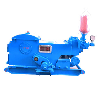
Chickasha Mud Pump specializes in complete fluid end refurbishment. The new 7500 PSI mud pump module manufacturing is compatible with the most popular industry designs. It is manufactured at our facility with U.S. forged steel and is a high-quality OEM aftermarket product. Contact us.

Cement compositions may be used in a variety of subterranean operations. For example, in subterranean well construction, a pipe string (e.g., casing, liners, expandable tubulars, etc.) may be run into a wellbore and cemented in place. The process of cementing the pipe string in place is commonly referred to as “primary cementing.” In a typical primary cementing method, a cement composition may be pumped into an annulus between the walls of the wellbore and the exterior surface of the pipe string disposed therein. The cement composition may set in the annular space, thereby forming an annular sheath of hardened, substantially impermeable cement (i.e., a cement sheath) that may support and position the pipe string in the wellbore and may bond the exterior surface of the pipe string to the subterranean formation. Among other things, the cement sheath surrounding the pipe string functions to prevent the migration of fluids in the annulus, as well as protect the pipe string from corrosion. Cement compositions also may be used in remedial cementing methods, for example, to seal cracks or holes in pipe strings or cement sheaths, to seal highly permeable formation zones or fractures, to place a cement plug, and the like.
A broad variety of cement compositions have been used in subterranean cementing operations. In some instances, set-delayed cement compositions have been used. Set-delayed cement compositions are characterized by remaining in a pumpable fluid state for an extended period of time (e.g., at least about 1 day to about 2 weeks or more). When desired for use, the set-delayed cement compositions should be capable of being activated whereby reasonable compressive strengths are developed. For example, a cement set activator may be added to a set-delayed cement composition whereby the composition sets into a hardened mass. Among other things, the set-delayed cement composition may be suitable for use in wellbore applications, for example, where it is desired to prepare the cement composition in advance. This may allow, for example, the cement composition to be stored prior to its use. In addition, this may allow, for example, the cement composition to be prepared at a convenient location and then transported to the job site. Accordingly, capital expenditures may be reduced due to a reduction in the need for on-site bulk storage and mixing equipment. This may be particularly useful for offshore cementing operations where space onboard the vessels may be limited.
Drilling requires the use of drilling fluid or as it is also known, drilling mud. One problem associated with drilling may be the undesirable loss of drilling fluid to the formation. Such lost fluids typically may go into, for example, fractures induced by excessive mud pressures, into pre-existing open fractures, or into large openings with structural strength in the formation. This problem may be referred to as “lost circulation,” and the sections of the formation into which the drilling fluid may be lost may be referred to as “lost circulation zones.” In addition to drilling fluids, problems with lost circulation may also be encountered with other treatment fluids, for example, spacer fluids, completion fluids (e.g., completion brines), fracturing fluids, and cement compositions that may be introduced into a well bore.
The present embodiments relate to subterranean operations and, more particularly, in certain embodiments, to set-delayed cement compositions and methods of using set-delayed cement compositions in subterranean formations. Lost circulation fluids comprising set-delayed cement compositions may be used to prevent the loss of a variety of treatment fluids. One of the many potential advantages to these methods and compositions are that they may immediately plug off or bridge lost circulation zones by developing sufficient static gel strength in a short time frame to be effective at lost circulation control. Other advantages are that they may set to form a hardened mass, possess sufficient compressive strength to support well structures, may isolate subterranean zones, and may be thixotropic (e.g., shear-thinning or shear-sensitive) so that the fluids should remain pumpable long enough for placement, but when static, should develop gel strength quickly.
Embodiments of the set-delayed cement compositions may generally comprise water, pumice, hydrated lime, and a set retarder. Optionally, the set-delayed cement compositions may further comprise a dispersant. Advantageously, embodiments of the set-delayed cement compositions may be capable of remaining in a pumpable fluid state for an extended period of time. For example, the set-delayed cement compositions may remain in a pumpable fluid state for at least about 1 day or longer. Advantageously, the set-delayed cement compositions may develop reasonable compressive strengths after activation. The set-delayed cement compositions may be suitable for a number of subterranean cementing operations, including those in subterranean formations having bottom hole static temperatures ranging from about 100° F. to about 450° F. or even greater. In some embodiments, the set-delayed cement composition may be used in subterranean formations having relatively low bottom hole static temperatures, e.g., temperatures less than about 200° F.
The water used in embodiments of the set-delayed cement compositions may be from any source, provided that it does not contain an excess of compounds that may undesirably affect other components in the set-delayed cement compositions. For example, a set-delayed cement composition may comprise fresh water or salt water. Salt water generally may include one or more dissolved salts therein and may be saturated or unsaturated as desired for a particular application. Seawater or brines may be suitable for use in certain embodiments. Further, the water may be present in an amount sufficient to form a pumpable slurry. In certain embodiments, the water may be present in the set-delayed cement composition in an amount in the range of from about 33% to about 200% by weight of the pumice. In certain embodiments, the water may be present in the set-delayed cement compositions in an amount in the range of from about 35% to about 70% by weight of the pumice. One of ordinary skill in the art with the benefit of this disclosure will recognize the appropriate amount of water for a chosen application.
Optionally, defoaming additives may be included in the set-delayed cement compositions to, for example, reduce tendency for the cement composition to foam during mixing and pumping of the cement compositions. Examples of suitable defoaming additives include, but are not limited to, polyol silicone compounds. Suitable defoaming additives are available from Halliburton Energy Services, Inc., under the product name D-AIR™ defoamers.
Optionally, thixotropic additives may be included in the set-delayed cement compositions to, for example, provide a cement composition that can be pumpable as a thin or low viscosity fluid, but when allowed to remain quiescent attains a relatively high viscosity. Among other things, thixotropic additives may be used to help control free water, create rapid gelation as the slurry sets, combat lost circulation, prevent “fallback” in annular column, and minimize gas migration. Examples of suitable thixotropic additives include, but are not limited to, gypsum, water soluble carboxyalkyl, hydroxyalkyl, mixed carboxyalkyl hydroxyalkyl either of cellulose, polyvalent metal salts, zirconium oxychloride with hydroxyethyl cellulose, or a combination thereof.
As previously mentioned, the set-delayed cement compositions may have a delayed set in that they remain in a pumpable fluid state for an extended period of time. For example, the set-delayed cement compositions may remain in a pumpable fluid state at a temperature, for example, about 100° F., for a period of time from about 1 day to about 7 days or more. In some embodiments, the set-delayed cement compositions may remain in a pumpable fluid state at a temperature, for example, about 100° F., for at least about 1 day, about 7 days, about 10 days, about 20 days, about 30 days, about 40 days, about 50 days, about 60 days, or longer. A fluid is considered to be in a pumpable fluid state where the fluid has a consistency of less than 70 Bearden units of consistency (“Be”), as measured on a high-temperature high-pressure consistometer at room temperature (e.g., about 80° F.) in accordance with the procedure for determining cement thickening times set forth in API RP Practice 10B-2, Recommended Practice for Testing Well Cements, First Edition, July 2005.
The set-delayed cement compositions may comprise properties that would be beneficial for use as a lost circulation treatment fluid. For example, the lost circulation composition may develop static gel strength in a short time frame enabling them to be effective at lost circulation control. By way of further example, the set-delayed cement compositions may set to form a hardened mass with sufficient compressive strength to support well structures. Additionally, the set-delayed cement compositions may be thixotropic (e.g., shear-thinning or shear-sensitive) so that the fluids should remain pumpable long enough for placement, but when static, should develop gel strength quickly.
Where τ is the shear stress, μ∞ is the consistency coefficient of the fluid, γ is the shear rate, n is the shear-thinning index, and τ0is the yield stress. A shear-thinning index of less than 1 indicates that the fluid is shear-thinning, whereas a value of n that is greater than 1 indicates that the fluid is shear-thickening. Thus, a shear-thinning fluid must have a shear-thinning index of less than 1 when measured according to the Herschel-Bulkley model. The thixotropic and shear-thinning dual nature of lost circulation treatment fluids will therefore remain fluid while exposed to the agitation of pumping (or any other agitation), however, when the lost-circulation treatment fluid flows into a lost circulation zone and away from a source of agitation the lost circulation treatment fluid will thicken to seal the lost circulation zone and prevent fluid migration into the lost circulation zone of any fluid flowing adjacent to the sealed lost circulation zone.
As previously mentioned, lost circulation zones are often encountered into which drilling fluid may be lost. As a result, drilling typically must be terminated with the implementation of remedial procedures, for example. In accordance with embodiments, the lost circulation treatment fluids may be used to seal the lost circulation zones to prevent the uncontrolled flow of treatment fluids into or out of the lost circulation zones, e.g., lost drilling fluid circulation, crossflows, underground blow-outs and the like. In an embodiment, a lost circulation treatment fluid comprising a set-delayed cement composition may prepared. After preparation, the lost circulation treatment fluid may be introduced into the lost circulation zone. In an embodiment, the lost circulation treatment fluid is pumped through one or more openings at the end of the string of drill pipe. For example, the lost circulation treatment fluid may be pumped through the drill bit. Once placed into the lost circulation treatment fluid, the lost circulation treatment fluid should set to form a hardened mass inside the lost circulation zone. This hardened mass should seal the zone and control the loss of subsequently pumped drilling fluid, which allows for continued drilling. In addition to drilling fluids, embodiments of the lost circulation treatment fluids may also be used to control lost circulation problems encountered with other treatment fluids, for example, spacer fluids, completion fluids (e.g., completion brines), fracturing fluids, and cement compositions (set-delayed or otherwise) that may be placed into a wellbore.
A system for sealing a lost circulation zone in a subterranean formation may be provided. The system may comprise a lost circulation treatment fluid for placement into the lost circulation zone. The lost circulation treatment fluid may comprise pumice, hydrated lime, and a set retarder. The lost circulation treatment fluid may further comprise mixing equipment capable of missing the lost circulation treatment fluid; and pumping equipment capable of pumping the lost circulation treatment fluid into the lost circulation zone.
A pump 120 (e.g., a mud pump) circulates lost circulation treatment fluid 122 through a feed pipe 124 and to the kelly 110, which conveys the lost circulation treatment fluid 122 downhole through the interior of the drill string 108 and through one or more orifices in the drill bit 114. The lost circulation treatment fluid 122 may be introduced prior to, concurrently with, or subsequent to the introduction of a drilling fluid or other treatment fluid (not shown) into the wellbore. The lost circulation treatment fluid 122 may then contact lost circulation zone 125. The lost circulation treatment fluid 122 that contacts lost circulation zone 125 may no longer be exposed to sufficient shear force to remain fluid and once static, lost circulation treatment fluid 122 may thicken to seal lost circulation zone 125 and eventually set to form a hardened mass. The lost circulation treatment fluid 122 that does not contact a lost circulation zone 125 may then be circulated back to the surface, either with or without the presence of another fluid (e.g., drilling fluid) via an annulus 126 defined between the drill string 108 and the walls of the wellbore 116. At the surface, the recirculated or spent lost circulation treatment fluid 122 exits the annulus 126 and may be conveyed to one or more fluid processing unit(s) 128 via an interconnecting flow line 130. After passing through the fluid processing unit(s) 128, a “cleaned” lost circulation treatment fluid 122 may be deposited into a nearby retention pit 132 (i.e., a mud pit). While illustrated as being arranged at the outlet of the wellbore 116 via the annulus 126, those skilled in the art will readily appreciate that the fluid processing unit(s) 128 may be arranged at any other location in the drilling assembly 100 to facilitate its proper function, without departing from the scope of the scope of the disclosure.
As mentioned above, the disclosed lost circulation treatment fluid 122 which comprises the set-delayed cement compositions disclosed herein, may directly or indirectly affect the components and equipment of the drilling assembly 100. For example, the disclosed lost circulation treatment fluid 122 may directly or indirectly affect the fluid processing unit(s) 128 which may include, but is not limited to, one or more of a shaker (e.g., shale shaker), a centrifuge, a hydrocyclone, a separator (including magnetic and electrical separators), a desilter, a desander, a separator, a filter (e.g., diatomaceous earth filters), a heat exchanger, any fluid reclamation equipment. The fluid processing unit(s) 128 may further include one or more sensors, gauges, pumps, compressors, and the like used store, monitor, regulate, and/or recondition the exemplary lost circulation treatment fluid 122.
The lost circulation treatment fluid 122 may directly or indirectly affect the pump 120, which representatively includes any conduits, pipelines, trucks, tubulars, and/or pipes used to fluidically convey the lost circulation treatment fluid 122 downhole, any pumps, compressors, or motors (e.g., topside or downhole) used to drive the lost circulation treatment fluid 122 into motion, any valves or related joints used to regulate the pressure or flow rate of the lost circulation treatment fluid 122, and any sensors (i.e., pressure, temperature, flow rate, etc.), gauges, and/or combinations thereof, and the like. The disclosed lost circulation treatment fluid 122 may also directly or indirectly affect the mixing hopper 134 and the retention pit 132 and their assorted variations.
The disclosed lost circulation treatment fluid 122 may also directly or indirectly affect the various downhole equipment and tools that may come into contact with the lost circulation treatment fluid 122 such as, but not limited to, the drill string 108, any floats, drill collars, mud motors, downhole motors and/or pumps associated with the drill string 108, and any MWD/LWD tools and related telemetry equipment, sensors or distributed sensors associated with the drill string 108. The disclosed lost circulation treatment fluid 122 may also directly or indirectly affect any downhole heat exchangers, valves and corresponding actuation devices, tool seals, packers and other wellbore isolation devices or components, and the like associated with the wellbore 116. The disclosed set-delayed cement composition may also directly or indirectly affect the drill bit 114, which may include, but is not limited to, roller cone bits, PDC bits, natural diamond bits, any hole openers, reamers, coring bits, etc.
While not specifically illustrated herein, the disclosed lost circulation treatment fluid 122 may also directly or indirectly affect any transport or delivery equipment used to convey the lost circulation treatment fluid 122 to the drilling assembly 100 such as, for example, any transport vessels, conduits, pipelines, trucks, tubulars, and/or pipes used to fluidically move the lost circulation treatment fluid 122 from one location to another, any pumps, compressors, or motors used to drive the lost circulation treatment fluid 122 into motion, any valves or related joints used to regulate the pressure or flow rate of the lost circulation treatment fluid 122, and any sensors (i.e., pressure and temperature), gauges, and/or combinations thereof, and the like.
FIGS. 2 and 3 illustrate an example technique for placing a lost circulation treatment fluid 214 comprising the set-delayed cement compositions disclosed herein into a lost circulation zone 225 while cementing equipment and casing are present in the wellbore 222. Such an embodiment may be used, for example, when it is desired to reduce the loss of displacement fluid into a lost circulation zone 225. FIG. 2 illustrates surface equipment 210 that may be used in placement of lost circulation treatment fluid 214 in accordance with certain embodiments. It should be noted that while FIG. 2 generally depicts a land-based operation, those skilled in the art will readily recognize that the principles described herein are equally applicable to subsea operations that employ floating or sea-based platforms and rigs, without departing from the scope of the disclosure. Additionally, it should be noted that lost circulation treatment fluid 214 may be introduced prior to, concurrently with, or subsequent to the introduction of any other treatment fluid (e.g., a displacement fluid, competition fluid, etc.) into wellbore 222. As illustrated by FIG. 2, the surface equipment 210 may include a cementing unit 212, which may include one or more cement trucks. The cementing unit 212 may include mixing equipment 204 and pumping equipment 206 as will be apparent to those of ordinary skill in the art. The cementing unit 212 may pump lost circulation treatment fluid 214 through a feed pipe 216 and to a cementing head 218 which conveys the lost circulation treatment fluid 214 downhole.
With continued reference to FIG. 3, the lost circulation treatment fluid 214 may be pumped down the interior of the casing 230. The lost circulation treatment fluid 214 may be allowed to flow down the interior of the casing 230 through the casing shoe 242 at the bottom of the casing 230 and up around the casing 230 into the wellbore annulus 232. As the lost circulation treatment fluid 214 flows upward through the annulus 232, lost circulation treatment fluid 214 may contact lost circulation zones 225. If lost circulation treatment fluid 214 contacts a lost circulation zone 225, lost circulation treatment fluid 214 may flow into lost circulation zone 225 and may become static if sufficiently removed from a shear force. If static, lost circulation treatment fluid 214 may rapidly develop gel strength. Once sufficiently gelled, lost circulation treatment fluid 214 may then seal lost circulation zone 225 and prevent the loss of any treatment fluids (not shown) that subsequently flow adjacent to lost circulation zone 225. Over time, lost circulation treatment fluid 214 may be allowed to harden and set in lost circulation zone 225, for example, to form a cement sheath that supports and positions the casing 230 in the wellbore 222. While not illustrated, other techniques may also be utilized for introduction of the lost circulation treatment fluid 214. By way of example, reverse circulation techniques may be used that include introducing the lost circulation treatment fluid 214 into the lost circulation zone 225 by way of the wellbore annulus 232 instead of through the casing 230.
Any of the lost circulation treatment fluid 214 that does not contact a lost circulation zone 225 may exit the wellbore annulus 232 via a flow line 238 and be deposited, for example, in one or more retention pits 240 (e.g., a mud pit), as shown on FIG. 2.
The exemplary set-delayed cement composition disclosed herein may directly or indirectly affect one or more components or pieces of equipment associated with the preparation, delivery, recapture, recycling, reuse, and/or disposal of the disclosed set-delayed cement composition. For example, the disclosed set-delayed cement composition may directly or indirectly affect one or more mixers, related mixing equipment, mud pits, storage facilities or units, composition separators, heat exchangers, sensors, gauges, pumps, compressors, and the like used generate, store, monitor, regulate, and/or recondition the exemplary set-delayed cement composition. The disclosed set-delayed cement composition may also directly or indirectly affect any transport or delivery equipment used to convey the set-delayed cement composition to a well site or downhole such as, for example, any transport vessels, conduits, pipelines, trucks, tubulars, and/or pipes used to compositionally move the set-delayed cement composition from one location to another, any pumps, compressors, or motors (e.g., topside or downhole) used to drive the set-delayed cement composition into motion, any valves or related joints used to regulate the pressure or flow rate of the set-delayed cement composition, and any sensors (i.e., pressure and temperature), gauges, and/or combinations thereof, and the like. The disclosed set-delayed cement composition may also directly or indirectly affect the various downhole equipment and tools that may come into contact with the set-delayed cement composition such as, but not limited to, wellbore casing, wellbore liner, completion string, insert strings, drill string, coiled tubing, slickline, wireline, drill pipe, drill collars, mud motors, downhole motors and/or pumps, cement pumps, surface-mounted motors and/or pumps, centralizers, turbolizers, scratchers, floats (e.g., shoes, collars, valves, etc.), logging tools and related telemetry equipment, actuators (e.g., electromechanical devices, hydromechanical devices, etc.), sliding sleeves, production sleeves, plugs, screens, filters, flow control devices (e.g., inflow control devices, autonomous inflow control devices, outflow control devices, etc.), couplings (e.g., electro-hydraulic wet connect, dry connect, inductive coupler, etc.), control lines (e.g., electrical, fiber optic, hydraulic, etc.), surveillance lines, drill bits and reamers, sensors or distributed sensors, downhole heat exchangers, valves and corresponding actuation devices, tool seals, packers, cement plugs, bridge plugs, and other wellbore isolation devices, or components, and the like.
I’ve run into several instances of insufficient suction stabilization on rigs where a “standpipe” is installed off the suction manifold. The thought behind this design was to create a gas-over-fluid column for the reciprocating pump and eliminate cavitation.
When the standpipe is installed on the suction manifold’s deadhead side, there’s little opportunity to get fluid into all the cylinders to prevent cavitation. Also, the reciprocating pump and charge pump are not isolated.
The suction stabilizer’s compressible feature is designed to absorb the negative energies and promote smooth fluid flow. As a result, pump isolation is achieved between the charge pump and the reciprocating pump.
The isolation eliminates pump chatter, and because the reciprocating pump’s negative energies never reach the charge pump, the pump’s expendable life is extended.
Investing in suction stabilizers will ensure your pumps operate consistently and efficiently. They can also prevent most challenges related to pressure surges or pulsations in the most difficult piping environments.


 8613371530291