
emsco mud pump free sample

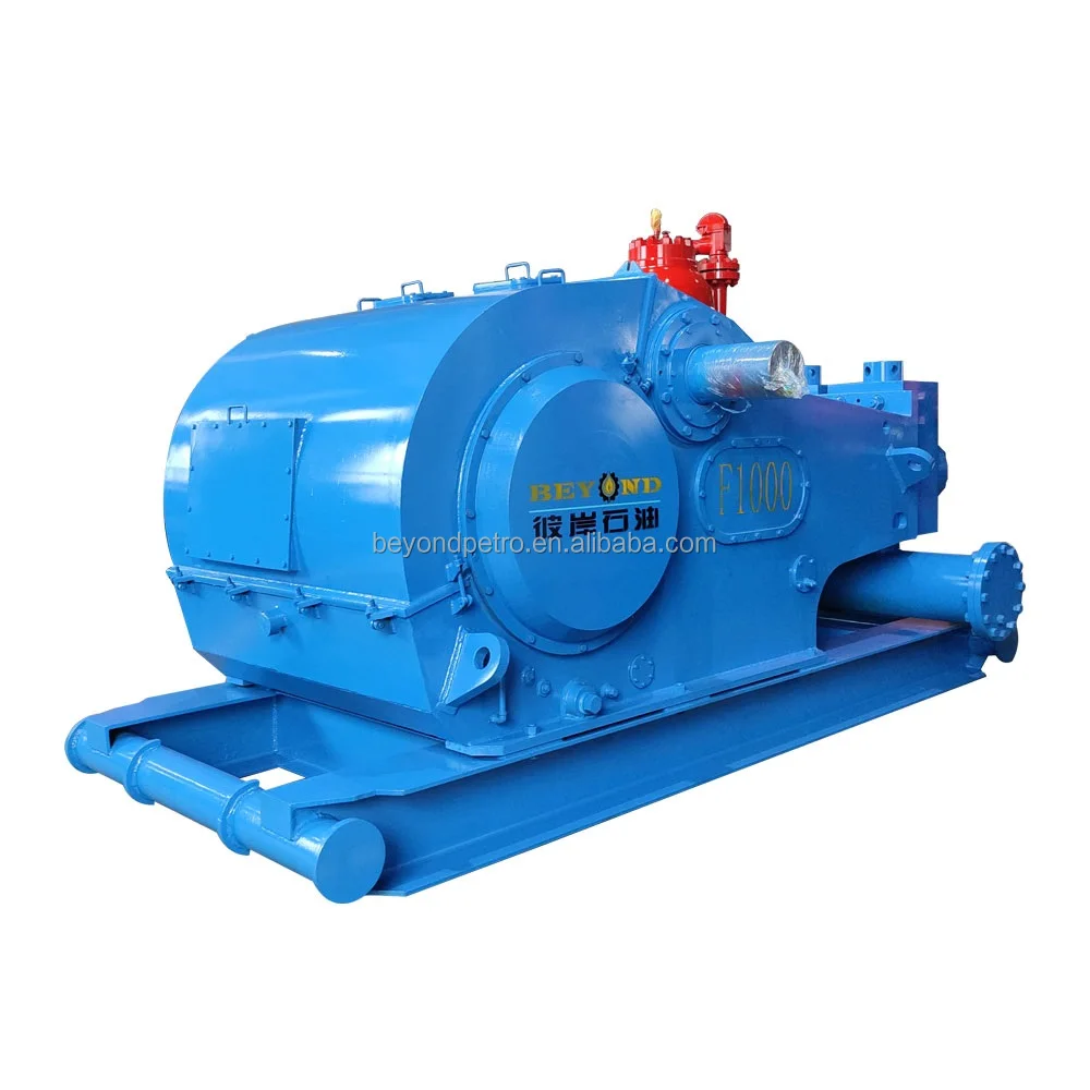
Choose a used Emsco FB-1600 Triplex Mud Pump from our inventory selection and save yourself some money on your next shallow drilling oilfield project. This Emsco FB-1600 Triplex Mud Pump is used and may show some minor wear.
We offer wholesale pricing on new Emsco FB-1600 Triplex Mud Pump and pass the savings on to you. Contact us to compare prices of different brands of Mud Pump. This equipment is brand new and has never been used.
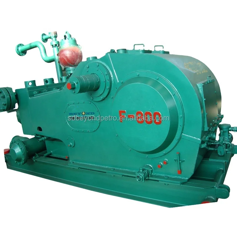
Our large network often has surplus Emsco FB-1600 Triplex Mud Pump that go unused from a surplus purchase or a project that was not completed. Contact us to see what Emsco FB-1600 Triplex Mud Pump we have in inventory. The surplus Emsco FB-1600 Triplex Mud Pump are considered new but may have some weathering depending on where it was stored. Surplus oilfield equipment is usually stored at a yard or warehouse.
We have refurbished Mud Pumpthat have been used and brought up to functional standards. It is considered a ready to use, working Mud Pump. Please contact us for more information about our refurbished Emsco FB-1600 Triplex Mud Pump. These Mud Pump have been used and brought up to functional standards. It is considered a working Mud Pump. Please contact us for more information about the product.

Our triplex and quintuplex pumps, cementing and fracturing equipments are interchangeable to global famous brands: Weir spm, Serva, BJ, Gardner Denver, Halliburton, Oilwell, OPI and so on. We also make a full line of Module assy and fluid end expendables for popular mud pumps in the world, including continental Emsco, National, Gardner Denver, Oilwell, Ideco, Wheatly, Wilson,with, opi, Ellis Williams, etc.

⊙Mud pump spare parts of abroad brand:Eg. Liner, piston, valve assembly, valve seat, valve spring, valve rubber could be alternative for original with lower price.
⊙Original brand:Emsco、Gardner-Denver, National oilwell, Ideco, Brewster, Drillmec, Wirth, Ellis, Williams, OPI, Mud King, LEWCO, Halliburton, SPM, Schlumberger, Weatherford.
A wide variety of emsco mud pumps options are available to you, such as 1 year, not available and 2 years.You can also choose from new, emsco mud pumps,as well as from energy & mining, construction works , and machinery repair shops emsco mud pumps, and whether emsco mud pumps is 1.5 years, 6 months, or unavailable.

Our invention relates a pump adapted to pump fluid and relates in particular to slush pumps such as are commonly employed in the oil well drilling art for pumping rotary mud or slush into the well during the drilling operation.
Although our invention is useful in many industries wherein fluid is pumped under pressure, it has a particular utility in the oil well drilling industry and therefore that form of our invention designed for use as a slush pump in the oil well drilling industry will be described herein.
In order that the features and advantages of our invention may be readily understood the oil well drilling industry will now be referred to. It is common practice to drill oil wells by use of a bit of drill connected to the lower end of a drill pipe which is extended into the well, this drill pipe being rotated by a rotary machine placed on the derrick floor. Connected to the upper end of the string of drill pipe is a swivel by means of which the string of drill pipe is supported by the travelling block and by means of which rotary mud may be pumped into the upper end of the drill pipe. The swivel ordinarily employed in this art includes a goose neck to which a flexible hose is connected, the flexible hose being connected to a stand pipe which in turn is connected to the slush pump or mud pump which is usually positioned at one side of the derrick floor.
As the well drilling industry has advanced and wells drilled deeper the slush pump is called upon to deliver the rotary mud or slush at relatively high pressure in order to force the same downwardly through the drill pipe to the lower end of the well and then upwardly through the well around the drill pipe and to the surface of the ground. At the present time it is not uncommon for the slush pump to deliver 1500 pounds per square inch. This rotary mud or slush usually consists of a mixture of earth and water so as to form a muddy consistency which can be suitably pumped as a fluid, and it is common practice to mix with the rotary mud, heavier material, such as iron oxide, barium sulphate, and the like, in order to give the rotary mud sufficient weight to support the walls of the hole being drilled. The rotary mud therefore is a highly abrasive material which produces a very sovere attritional or wearing action on the various parts of the slush pump.
Due to the pressures which must be pumped and due to the abrasive qualities of the slush, the slush pump is subjected to considerable punishment and it is therefore necessary for the pumps, as they are constructed today, to be quite massive in size and to incorporate heavy castings, which, of course, result in the slush pump being relatively heavy and awkward to transport.
Our invention deals primarily with a slush pump of the power-driven type, wherein rotative power from an external source is applied to a pinion shaft and by use of gears and a means of transforming it to reciprocating motion is delivered to a fluid end having reciprocating pistons for the pumping of fluid.
It is an object of our invention to provide a slush pump in which the power end of the pump, instead of being made from massive and sizeable castings, is fabricated; that is, the various parts are made from high tensile strength structural steel shapes and plates which are formed and welded together. We have found that by such a method of construction which incorporates valuable features of design and construction of our invention that not only is the slush pump more economical to produce but the necessary strength is obtained by less weight and less size of the various parts. The slush pump constructed in accordance with this object of our invention is considerably lighter and more compact than prior art constructions employing casting.
It is a still further object of our invention to provide a double-acting duplex slush pump, that is, one having two cylinders both of which are double acting, the pistons operating out of phase in order to pump a substantially continuous stream under uniform pressure, and in which the power frame is made relatively light as compared to slush pumps now used in the prior art but in which the power frame is especially designed to withstand the forces and stresses transmitted through it during the operation of the pump.
It is a still further object of our invention to 15 provide a pump of the character referred to having a power frame in which the members are secured together as by welding, and which includes an X-frame structure extending from the force end to the reaction end of the frame, and 0o in which all members are designed to resist tension, compression and diagonal stresses.
It is another object of our invention to provide a pump of the character referred to in which the points of application of the forces to the power 5 frame at the fluid end or pump end are closer 2 2,331, together than the reaction points at the opposite end, and in which the forces applied at either of the force points are transmitted directly to both reaction points.
It is another object of our invention to provide a slush pump in. which the stuffing box positioned around the piston rod is removable from the pump without disconnecting the fluid end of the pump from the power end thereof.
It is another object of our invention to provide a slush pump in which the stuffing box for the cross-head rod is removable for replacement or repair.
A further object of our invention is-to provide a2 pump in which a removable cross-head rod stuff- i1 ing box is mounted in a frame partition without the necessity of drilling or tapping bolt or- stud: holes in said partition.
A still further object of our invention is to provide a slush pump employing a deflector baffle 2 placed around the pump rod between the piston rod stuffing box- and cross-head rod stuffing box which closes the space and includes a wiping means which wipes any rotary mud from the rod. 2 Another object of our invention is to provide a construction of the character pointed out in the preceding paragraphs in which the deflector baffle is removable for the convenience of assembling and also to permit the installing or removal 3 of the piston rod stuffing box from place.
Referring to the drawings in which we have illustrated our invention embodied in a slush pump adapted for use in the oil drilling industry, Fig. 1 is an elevational view of such a slush pump.
Fig. 6 is a vertical, sectional view through the slush pump of our invention taken through the plane of one of the pump cylinders, one of the cross-heads and one of the eccentrics showing the various parts of one half of the pump.
Fig. 7 is an enlarged fragmentary sectional view showing the details of construction and the manner in which the various stuffing boxes are arranged to prevent leakage of fluid from the pump end into the lubricated" enclosed portion of the power end.
Fig 11 is a fragmentary sectional view taken on the line 11-11 of Fig. 6 showing the manner in which the various stuffing box parts may be removed without disconnecting the pump end and the power end of the apparatus from each other.
Referring to the drawings in detail our inven0 tion. provides a base structure 30 on which is supported the power end of the slush pump 31 and" the pump or fluid end of the slush pump 32.
As shown in Figs. 3, 4, 5, 6, and 8, the frame 35 construction which may be referred- to as the power frame includes a pair of longitudinal beams, 36 each of which may consist of a pair of channels welded together as shown. At the forward end of the two beams 35 which are. spaced 40 apart as- shown, and which extend parallel to each other, there is a vertical wall or end member 37 which is- secured to the forward end of the longitudinal, beams 36 preferably by welding as illustrated in Fig. 5. Extending transversely be5.i tween. the forward end of the two beams. 36 and secured thereto and also secured to the end wall 37 is-an intermediate crcss-angle 389, which forms a part of the frame. The rearward ends of the beams 36 are connected together by an end beam 5,"1 39 which is in the form of an upstanding channel as shown in Figs. 3 and 5. Extending forward from the intermediate wall 37 in a horizontal plane is an X-frame 40" which consists of two longitudinal members 41 which cross each other :5 and are welded together at 42 in a plane corresponding to the vertical longitudinal axis of the slush pump. At the forward end of the X-frame is a front member or abutment plate 44 which extends in a vertical plane as shown. The rearI;, ward ends of the members 41 are welded to the vertical wall 37 as indicated at 45 while the forward ends of the members 41 are welded to the abutment plate 44 as indicated at 46. The rearward ends of the members 41 are in alignment 65 with the longitudinal axes of the beams 36 while the forward ends of the members 41 are in alignment with the axes A-A of the cylinders of the fluid end of the pump, as will be described. Positioned concentric to the axes A-A are barrels 70 or tubular members 48 which are positioned side by side in a horizontal plane as illustrated. The forward ends of the barrels 48 are welded to the rear surface of the front member, or abutment plate 44. The rearward ends of the barrels 48 75 project rearwardly through openings 49 formed in the vertical wall 37, and are welded to the vertical wall as shown. It will be seen that the barrels 48 are positioned directly above the Xframe 40. For the purpose of stiffening the barrels 48 there is secured as by welding to the upper portion of each barrel a stiffening member 50, the forward end of which is welded to the front member 44 and the rearward end of which is welded to the intermediate or vertical wall 37.
As shown in Fig. 6 our invention provides a jack shaft or pinion shaft 90 which, as shown in Fig. 2, extends outwardly from opposite sides of the pump construction so that a drive means may be applied to either end thereof. The jack shaft 90 is rotatably supported by bearings 91 mounted within bearing retainers 92 which are in turn removably secured in the journals 65.
Extending from the cross-head block 192 in a direction toward; the fluidi end of the slush pump is a cross-head- rqd 239 which extends through theroAs-head stuflng box 1898 Threadedly connected, to each cross-headrd rod 30is a piston rod 231, this connection being, made by a threaded end 2~:, of the piston: rod, 231 screwing- into a threaded opening provided by each cross-head rod, 23. A lock nut~ 23 is provided, and in the preferred form of our invention we provide a baffle. plate 234 which- is secured at the end of each -o cross-head rod, 230. by. each nut 223: which prevents any, foreign matter, or slush, or- the like from being directed against the stuffingbox parts 1.i98. This piston rod 231 extends leftwardly toward the fluid end" of the pump, and passes through a pump stuffing box 236. and into the fluid end of the pump, as will be discussedp later.
The pump stuffing box 236 is provided in the form of a body 245 which has an outwardly extending flange 246. This flange 24; rests within a cylindrical opening 247 formed in the abutment wall 44" and also in a widening ring 248 which is welded to the abutment wall 44 inside each of the barrels 48. Cylinders of the fluid end of the pump, which will be designated by the numeral 250, have end faces 251 which are clamped against the leftward face of the abutment wall 44 by means of stud bolts 252 which extend through the abutment wall 44 and widening ring 248. The cylinders 250, of course, are 5T) secured with their axes concentric to the axes A-A shown on Fig. 5. Each cylinder 250 carries an end ring 254 from which studs 255 extend, as shown in Figs. 7" and 8. These studs 255 extend through openings 256 provided in the (i6 flanges 246 and nuts 257 are employed to secure the body 246 against the adjacent end plate 254.
Between the two stuffing boxes 189 and 236 we provide a deflector means designated by the numeral 265. This construction includes an annular support 296 which is secured in each barrel 48 by welding. Each support provides an annalay opening 267 in which a deflector wall 268 is received. The deflector wall 208 accurately fits the opening 267 and is aligned thereby. The deflector wall 28,. has an outwardly extending flange Z69 which engages the-rightvward wall of the support 2.6, Blaeed. on the- opposite side of the support 266, is. a: split ring 271, and extending through the, deflector wall, 268. and through the split rirg: 211 are bolts 212 which secure the ring 271 to the deflector wall 268 and in this way the deflector, wall is secured. in the annular support 266 without requiring drilling for bolts. Each of the. deflector walls, 26 has an opening 274 in which a rubber bushing 275 is positioned, this rubber bushing 275 of each assembly forming a running fit around the associated piston rod 23,1. The function of the rubber bushing 215 is to. prevent leakage of rotary mud or other foreign matter past the deflector means 265 and to wipe any foreign matter from the piston rod as it moves in a rightward direction.
The pump stuffing box 245 is, of course, provided to form a seal around the pump rod 231 so that there will be no leakage from the pump cylinders. In the event of leakage, through this stuffing box the deflector means 2.65 will ordinarily function to prevent foreign matter- from passing into the intermediate section 219. Any foreign matter which leaks into the end section 274 can be drained therefrom through the drain tube. 280. Should the, deflector means 265 fail, the baffle 234 functions to prevent any stream of fluid from being directed directly against the cross-head stuffing box 189. Should any foreign matter reach the cross-head rod 230, the cross-head stuffing box 189 functions to prevent foreign matter from entering the rightward end of the barrel 48 which, as will be seen, is in direct communication with the crank case and, in fact, forms a part thereof. Should, however, foreign matter in same way pass through these various protecting means which we provide and get into the lubricant, this lubricant before it is delivered to the oil pan kT is first passed through the settling chamber. 27 so that this foreign matter- will be separated therefrom.
Ready access may be had to the interior of the barrels 48 in view of the fact that we have provided hand holes 285 in the rightward end of the barrels 48 so that access may be had to that portion of the barrel in which the cross-head operates. Welded to the barrels around the hand holes 285 are box shaped members 286 to which hand hole covers 28, may be secured for closing the hand holes during normal operation of the sluush pump. By the remoal of the bolts 268 the hand hole covers 287 may be removed and access to the interior may be had. The intermediate sections 279 are rendered accessible through hand holes 290 formed in the barrels, these hand holes being surrounded by box structures 291 welded to the barrels, and which hand holes are closed by covers 292 removably secured in place by bolts 293. Access to the end section 278 of each of the barrels 48 may be had through inspection holes 294 which are always left open.
Through the inspection holes 2$4 the pump stuffing box 236 may be inspected and the gland thereof tightened. Through the hand hole 290 the stuffing box 189 may be inspected and the gland tightened, Likewise, the condition of the rubber bushing 275 may be inspected, It is one of the features of our invention that the various parts in the barrels may be reached for inspection and that the stuffing boxes 189, 236, and the deflector wall 268 may be removed from the slush pump without disconnecting the power end and fluid end of the apparatus. As illustrated in Fig. 11, when the piston rod 231 is disconnected from the cross-head rod 230 and the various parts of the stuffing box 236, including the body 245, the various parts of the stuffing box 189, including the body 237, the baffle 234, and the deflector wall 268 are disconnected from their supporting parts, they may be moved outwardly through the hand hole 290. It will be seen that the parts of the stuffing box 189 when disconnected may be moved leftwardly and then moved outwardly through the hand hole 290.
The fluid end of the slush pump of our invention is, as previously pointed out, mounted on the base 33. The fluid end includes the two cylinders 250 which, as previously explained, are rigidly secured against the abutment wall 44.
Supported on each of the skid beams 33 is an intake manifold 300 which has feet 301 which rest on the skid beams 33 and are removably secured thereto by bolts as shown. The details of construction do not constitute a part of the invention claimed herein, In the operation of the slush pump of our invention the eccentric members I 10 are so positioned with relation to each other that the eccentrics 113 are 900 out of phase; that is to say, they are spaced around the axis of rotation of the main shaft 98 a distance of 90° from each other. Any angular phase desired and in accordance with ordinary pump practice may, however, be employed. In operating the device adequate lubricant is, of course, placed in the crank case to assure proper lubrication of the parts, A drive means is connected to the jack shaft or pinion shaft 90 and through the interconnecting mechanism the two eccentrics 113 are rotated in order to move the cross-heads back and forth, which in turn move the pistons 372 in the liners 3711. When the piston, such, for example, as illustrated in Fig. 6, is moved from the position shown in full lines in a leftward direction fluid is drawn ,C into the rightward end of the cylinder through the suction valve and through the connecting portion of the suction manifold. At the same time any fluid which is in the leftward end of the cylinder is forced outwardly through the,.65 outlet valve and through the manifold pipe 365" into the manifold pot 364. At the same time, however, the piston in the other cylinder is moving in the opposite direction and fluid is being pumped from the right end of that other cylinder, through the outlet valve, the upper valve chest 360, and the manifold pipe 365 which directly opposes the manifold pipe which is connected to the valve chest associated with the left end of the first mentioned cylinder. It will be seen,,7, therefore, that at this time there are opposing flows of fluid into the exhaust manifold pot 364, and that instead of the stream of fluid engaging a wall the two streams of fluid are brought together and guided upwardly, and in this way wear is reduced. When the direction of movement of the pistons change the fluid which was, during the previously mentioned stroke of the pistons, drawn into the cylinder is then forced therefrom and fluid is drawn into the opposite end of the cylinder ready to be forced therefrom upon a change of direction of the pump piston.
This operation is, of course, in accordance with standard practice and is referred to here only so .5 that the construction of the discharge manifold may be explained and the value of its design referred to in connection with the flows of fluid outwardly from the opposite ends of the pump cylinders.
In Fig. 12a we have diagrammatically illustrated the essential parts of the power frame in order that the various forces transmitted therethrough during the operation of our pump may be illustrated.
We claim as our invention: 11. In a "pump of the class described, the coinbination of: longitudinal beams; an -end *wall member attached in transverse relation -to the forward-ends of said beams; a front Wall -nember spaced "forwardly of -said "end "wall meiber iin parallel relation thereto; barrels coiinected to said end wall member and said frdfit wall -iiember; operating means: supported -by said longitudinal beams behind said end wall himemiber; a pumping asseibly for said pump secired"to the "front of said front Vall m;eiiber; said pupiiiing assembly including a fluid displacing -·iipng elemenit; iinterconnecting means in said barrels for operatively connecting -said operating meais and"said pimping element; and-in"k-fi-atie"eonnected to -said end wall rmember and -naid f-roht wall member in a plane adjacent to :the -loWer faces of said "barrels, said X-frame ~6op~ating t 25 wall hiember. with said barrels tbo-absorb the reversing forces resulting from operation of said lhlid "eiid by said operating means.
2. In a pump of"the"class descreid,ttheb"io6fmibnation of: a pair of laterally- spaced "lo6iitudinal beains; an end member" cdiiprising aliransverse wall attached to the forwarhd "eds of said beams; a front meiiber co"riprisirng"a tratsverse wall spaced forwardly of "said -enid -rhemnber; :a pair of laterally spaced substantially -parallel barrels connected to said "end "mhenber -arid-said front "member, the ends of ssaid -barres -being open; supporting frames "secured to "said longitudinal beams anid said end"rimetiiberbebhind said end member; operating means isupported "by said frames in the space between "sadid longittdinal beams; a pumping "agslihbly fbr said"ptinp secured to the fi-drit of said "front hienibler; said pumping "assembly including a fluid displacing pumping -element; "and hitefrcdiiectihg "means extending through"and" gulded -i"i"sid"baftefs"for operatively coniecting said iperatinig irieais a"id "said pumping"elemxient.
3. In a pimp of the "class -described, "the coimbination of: a pair of :laterally -sadede"litgitiidinal beams; ah end member coniprising a" tirhsvirese wall attached"to the fdirward" ends of"said Beamfs; a fro6itmnember cbimprising za trdinsverse wall spaced forwardly of said"eiid meffiHr; "barrels connected to said end hmember "and saidifront member, said front member and said end nimmbner having openings c6inciding"with-thte eiids" f"said barrels; walls forming a case behind said end member; walls forming cross-head chadi"bers "i said barrels in cominunicatidn with said "ase; operating means in said case-disposed lbetween and"supported by said lorigitidifial bdais;"rosshead means in said cross--head "chanib:ers :an"d operatively donnected to said operating "hieads; a pumping assembly for said pumpoohhnecte"d-in front of said front member; said pumpirig assembly including a fluid displacinrg pu"niping-element; and interconnectihg :"ieans -odperatively connecting said cross-head -m:earis aihd -said pumping element.
-4. In a pump"of-the class described,"-the :ddiTbination of: spaced lonigitudirialtaietal"-ýea"s; -an end miember comprising a" tiLnsVerse nMIetal :wall welded to the forward erids of "said "idiis; "a frotit"wall member spaced forwardly of`said"rid wall "member; metal barrels in side by side -relation with the einds thereof welded to said -end wall mener ir-and said front wall member; walls forming a case behind said end wall meniber; walls forming -ross-head chambers in said barrels "in "commiinication with said case; operating means in said case supported by and between said beams; -cross4-head "meafs in said cross-head "hambers and operatively connected to said operdtiing iieans; a ipumping "assembly for said piimp"ddCnnected in froiit"of said front wall:member; -aid"pumping assembly-including a fluid displiacihg pumping element; interconnecting means dperatively connecting said "cross-head means "15 and said "pumping eleýhentt; a-cross-head stuffmng box at "the forward "part of each cross-head chamber; a pump stuffing"box ýat the forward -end df-each of said barrels "through which said fiftercdrihectinig mneans extends; -and crossing nemibers :extendbd below said barrels in a horiz"idftal plane"which is parallel to the-axes of said bafrels arid -extends "through said longitudinal `beams,"the"erids-f"Said crossing "members -being Weldeld "tb saidend :wall ineinber and said front . "na:pfiump- bf the"class "described,-the-combihatidn-df: -a-pair of sub"stahtially parallel lohgi.thiihul "beams; a transverse end wall member "ittached to"the forward ends of said beams; a transverse front wall mieinber spaced forwardly of said -ehd wall member; longitudin"al frame feinbers connected to said end wall member and said ýronit Vwall "ember, -and being closer "togeither than said "oihgitudinal -beams; crossing members "cdnnected "to said ehd wall member and to "said front wall member aild lying in a plane which :passes through "said longitudinal beams; a"pumping:assembly secu"red in"front of said froit "-wall mmber; "said punmping assembly "o0 including a fluid displacing "pumping element; operating means supported:by said longitudinal "beams in a position -between them; and -interconidectinig means operatively connecting said oprating mneans "and said -pumping element.
-6. "In a -puimp of the "class described, the cornbiniatin "of: a pair of "substantially parallel lon-gituidinal beams; a transverse end wall member attached to :the forward ends of said beams; a "transverse "front wall me"in ber "spaced forwardly of *saidd eihd wall miember; longitudinal "frame nmemnbers "connected "to said end wail member "and Said front wall mnember, and being closer to"gether than said longitudinal beams; crossing imehibe&rs lying ih-a horizontal plane which passes tliroiih said longitudinal beams `"connected to said ehd "wall memiber in "substantially "the vertical planes defined -by said longitudinal beams "and to "said "front wall mIember in substantially "the vertical planes defined by said longitudinal 0g fraame memfbers; -a pumping assembly .secured in frdfit"of said front wail member and- having cylinders in substantially the same vertical planes "as said -"longitudifial frame menbers; a fluid displacingpumping"eleienft in each"cylinder; operating -1eans supporte"; by and between said longitudinal "beais; -and -itercoddnecting mreans dperatively conniecting said"opel"atihg:-means, and said puimping "eIeneiits.
7. In a aupilxd piffuiphhaving - apair of putiping units in side by side itrelatidn, rsaid pumping units :each including a "Uid adisplacing :pumping elemefit, operating means"f-orsai"d pumpinPig units arid "coriiedting :i"earis -eithdiaig -from said -op"eratihg mrieans to the "puffiii ng eleiments of -said itd ipumping *uinits, the "coibiriatioh -of: a pair -of metal tubes in side by side relation; an end member comprising a transverse metal wall welded to the rear ends of said tubes, and having openings therein coinciding with said tubes; a front member comprising a transverse metal wall welded to the front ends of said tubes and having openings therein coinciding with said tubes; means for connecting said operating means and said pumping units respectively to said end member and said front member; and removable cylindric means within said tubes to guide said first mentioned connecting means.
8. In a duplex pump having a pair of pumping units in side by side relation, said pumping units each including a fluid displacing pumping element, operating means for said pumping units and connecting means extending from said operating means to the pumping elements of said pumping units, the combination of: a pair of metal tubes in side by side relation; an end member comprising a transverse metal wall welded to the rear ends of said tubes, and having openings therein coinciding with said tubes; a front member comprising a transverse metal wall welded to the front ends of said tubes and having openings therein coinciding with said tubes; metal cross-members extending from said end member to said front member in a plane parallel to the plane defined by the longitudinal axes of said tubes, and having the ends thereof welded to said end member and said front member; means for connecting said operating means and said pumping units respectively to said end member and said front mmeber; and means within said tubes to guide said first mentioned connecting means.

Created specifically for drilling equipment inspectors and others in the oil and gas industry, the Oil Rig Mud Pump Inspection app allows you to easily document the status and safety of your oil rigs using just a mobile device. Quickly resolve any damage or needed maintenance with photos and GPS locations and sync to the cloud for easy access. The app is completely customizable to fit your inspection needs and works even without an internet signal.Try Template
I’ve run into several instances of insufficient suction stabilization on rigs where a “standpipe” is installed off the suction manifold. The thought behind this design was to create a gas-over-fluid column for the reciprocating pump and eliminate cavitation.
When the standpipe is installed on the suction manifold’s deadhead side, there’s little opportunity to get fluid into all the cylinders to prevent cavitation. Also, the reciprocating pump and charge pump are not isolated.
The suction stabilizer’s compressible feature is designed to absorb the negative energies and promote smooth fluid flow. As a result, pump isolation is achieved between the charge pump and the reciprocating pump.
The isolation eliminates pump chatter, and because the reciprocating pump’s negative energies never reach the charge pump, the pump’s expendable life is extended.
Investing in suction stabilizers will ensure your pumps operate consistently and efficiently. They can also prevent most challenges related to pressure surges or pulsations in the most difficult piping environments.


 8613371530291