
hhf 1600 mud pump manual manufacturer

‘ancl then locked down to avoid the preset pressure changing.‘Upon builtin installation of the lube oif pump, as shown item 9 in Figure 13, the pump mast be

Safety warning:The power supply should be cut off and tag out while fixing and maintaining. Safety warning:Before the mud discharge manifold needs to be repaired, the bypass valve on pressure release line should be opened first, and let the pressure in discharge manifold to be released to zero.
The unitized drilling pump consists of drilling pump, power drive device, mud suction system, mud discharge system, is installed on the same skid and transported as a module. Since the unitized drilling pump has been installed and tested as per design requirements at manufacturer’s factory, the user needs only to install according to the requirements of drilling well site layout.
Safety warning 2:when high pressure mud manifold system needs to be maintained, it is a must to open the bypass valve on pressure release line and release the high pressure of discharge manifold to zero, then dismantle and repair .
at the side of the pump, and the water tank is installed below the frame, and the spraying pipe is fixed on frame above liner. The spraying water jetted out from spraying pipe onto liner and piston for washing, lubricating and cooling.
2.1 Use and application ....................................................................................................................... 2 2.2 Referenced tandards ...................................................................................................................... 2 2.3 Brief working principle ................................................................................................................. 2 2.4 Technical parameters ..................................................................................................................... 3 2.5 Performance parameters ................................................................................................................ 4 3 General configuration ............................................................................................................................. 4 3.1 General structure ........................................................................................................................... 4 3.2 Overall dimensions........................................................................................................................ 5 4 Introductions of main components ......................................................................................................... 6 4.1 Power end ........................................................................................................................................ 6 4.2 Fluid end .......................................................................................................................................... 8 5 Lubrication ........................................................................................................................................... 11 5.1 Splashing Lubrication.................................................................................................................. 11 5.2 Pressure Lubrication.................................................................................................................... 12 6 Unitized drilling pump.......................................................................................................................... 16 6.1 Diesel engine direct driven Drilling pump .................................................................................. 16 6.2 Compound transmission driven drilling pump ............................................................................ 16 6.3 Motor driven drilling pump ......................................................................................................... 16 7 Mud suction system .............................................................................................................................. 16 7.1 Suction pipeline (manifold)......................................................................................................... 16 7.2 Suction desurger .......................................................................................................................... 16 7.3 Suction filter ................................................................................................................................ 17 7.4 Valves on suction line.................................................................................................................. 17 8 Mud discharge System.......................................................................................................................... 17 8.1 Accessory manifold ..................................................................................................................... 17 8.2 Relief valve.................................................................................................................................. 17 8.3 Pressure release line .................................................................................................................... 17 8.4 Discharge filter ............................................................................................................................ 17
10.1.2.1 It is a must to start electric lubrication oil pump before starting drilling pump. Make sure that gears and crosshead of power end get fully lubricated before starting.
(102mm×305mm) should be placed at several positions under pump skid along the entire length. The foundation below mats should be 12″(305mm)wider than the width of the pump skid.
The gears, bearings, crosshead sliding ways of power end all adopt the combination of splash lubrication mode and forced lubrication mode. And the forced lubrication includes built-in mode and outer layout mode. The liners and pistons of fluid end are lubricated, flushed and cooled with the water supplied by spray pump.
Liner spraying device is consisted of spray pump, water tank, spraying manifold etc. Its function is to wash, lubricate and cool liner and piston during mud pump running in order to prolong the service life of liner and piston. The spraying pipe position is shown in Fig. 7.
10.1.3.1 Start with slow speed-the starting speed should be as low as possible, then speed up step by step. Ensure that fluid flowing speed inside suction pipeline can meet the pump suction action without any cavitation corrosion.
10.1.3.2 Natural suction operation-when the pump is running under natural suction condition, the pump speed is limited by the filling degree of pump. If some mental knocking sound can be heard from the fluid end while running,it means that pump has been cavitated and not fully- filled. At this moment, the charging pump should be started until the knocking sound disappeared and operation turn to normal, then the natural suction can be adopted again.
crosshead and guide to meet requirements. (2)Turn the crosshead 180° when replace the guide or disassemble the crankshaft assembly. (3)Recommend to overhaul the drilling pump every 2-3 years, inspect the main bearing, eccentric
Fig. 17 Accessory manifold and pressure release line (2)Dismantle the discharge manifold and discharge line. (3)Dismantle the connecting bolts for suction manifold and cylinder block . (4)Dismantle the connecting nuts between cylinder block and frame, then can the cylinder block module be removed. Caution:There is no need to dismantle the suction module, unless the suction manifold needs to be replaced. Replace the gasket ring or seal ring together while suction manifold or cylinder block module being replaced . 12.1.2 Piston and liner (1)Cranking :crank the pump and make the crosshead at proper position. (2) Dismantle the connection clamp between piston rod and extension rod, and crank mud pump to separate the extension rod from piston rod. Then use the lifting tool to hold liner inside, use the lifting device equipped on pump to hang the liner, and use a hammer to knock the liner lock loose, and finally lift out the liner and piton from frame top. (3)There is no need to remove piston core from piston rod when replacing piston rubber. Replacing the rubber only needs to remove the retainer (circlip) and clamping plate at the front of piston core. (4)Piston and piston core seal:screw off the piston rod locknut and dismantle the piston. A self-tightening seal ring is set between piston core and piston rod shoulder, normally it is durable, no need to replace.
1 Big skid of unitized mud pump 2 Motor 3 Gear oil pump 4 Pressure switch 5 Suction filter 6 Magnetic filter 7 Oil distributor 8 Drilling pump 9 Oil pressure gauge
At a port of the connecting line between the accessory manifold and the relief valve, we connect a bypass line with a valve to the pressure release line (which go back to suction tank) of relief valve, therefore, when we open the valve on the bypass line, the mud pressure can be released from the discharge manifold before disconnecting it for servicing.
1 suction oil filter 2 connector holderⅡ 3 oil pipe 3A pinion shaft nozzle 4 main bearing tubing 4A crosshead chamber connector holder I 5 pressure gauge 6 relief valve 7 oil channel 8 oil pipe 9 oil pump
12 Drilling pump servicing...................................................................................................................... 28 12.1 Fluid power end dismantling ...................................................................................................... 28 12.2 Main parts’ assembling of fluid end ............................................................................................ 30 12.3 Dismantling of power end .......................................................................................................... 32 12.4 Assembling the main parts of power end..................................................................................... 33 12.5 Replacement of air bag of discharge dampener........................................................................... 37
fluid end do reciprocating motion in liner and work together with suction valve and discharge valve to compress low pressure mud and discharge high pressure mud.
Assemble the valve body and valve rubber into a module with the clamping plate and retainer. After confirming no scoring and burr on valve seat external cone surface and clean, put the valve seat into the cleaned seat cone hole on cylinder block (pump deck).
This manual generally describes the technical specifications and performance parameters, drive principle, configuration, installation and adjustment, operation and maintenance, frequent failure and troubleshooting, replacement of consumable and other operational precautions etc.
For ensuring the normal operation of lubrication oil pump, the rotary direction of oil pump is shown in Fig. 10. For ensuring the lowest oil-supplying pressure of lubrication oil pump to be 5 psi (0.035MPa), the lowest stroke number of drilling pump should not be less than 25 SPM.
10.1.2.4 Before the drilling pump starting, ensure to top up cylinders and discharge manifold of fluid end fully. Because air inside pumps can not be exhausted completely under conditions with pressure, so it will seriously affect the stabilization of pump running and the service life of pistons and valves. The way to top up pump is: open the pressure-release line or mud gun line, start pump to run until the air inside being exhausted completely.
10.1.3.5 When the pump is pressure lubricated by built-in mode or mechanical transmission mode, for ensuring full lubrication of power end, the pump speed can’t be too low, i.e. the pump stroke can’t be lower than 25 SPM.
For ensuring lubrication oil of power end can be distributed properly while pump is running, the pump on foundation should be adjusted to be horizontal.
Note: when change liner, the liner seal should be replaced together. (3)Inspect the liner chamber of mud pump frame, clean it if there is too much mud sediment. (4)Inspect whether there is sufficient water in water tank for spraying pump or not, whether the cooling water is polluted or not, supplement water or change water and clean water tank in time if necessary. (5)Check the charging pressure of discharge pulsation dampener. (6)Inspect the reliability of the shear relief valve. (7)Loosen the piston rod clamp, turn the piston for a quarter cycle manually, tighten the clamp again. This can make the piston wear evenly and extend the service life of piston and liner. (8)Check the valve pot cover and cylinder head every 4 hours for looseness . (9)Observe the valve pot seal, liner seal and liner seal leakage hole, if mud is seen to flow out, please replace related seal timely.
10.1.1.1 Check if every part of the unitized drilling pump and pump itself are connected, installed and tightened according to relevant requirements, and check if there is any foreign matter exist in pump body or frame.
Replace the bladder of discharge pulsation dampener as per the following steps:( see Fig. 22) 12.5.1 Confirm the system pressure has been released completely ( as described before ). 12.5.2 Dismantle the cover 5, and insert a wood rod between the bladder and shell body. After flattening the bladder, then take it out from the top. 12.5.3 Check if the air bladder and the bottom plug are in good condition. Replace them with new one if damaged. 12.5.4 When installing a new air bladder, first flatten it and curl it up to spiral shape to make it can be put in from the top of the shell. After that, loosen and adjust the air bladder to make it contact the shell body properly, finally install the seal ring of the air bladder neck to the sealing shoulder of shell and coat some lubrication grease on the internal of the neck. 12.5.5 Install the cover 5, be sure not to make the air bladder neck deformed. 12.5.6 Tighten the nuts(R2)with pre-tighten torque of 1954~2255N.m. 12.5.7 Inflate the air bladder as per the requirement of clause 10.1.1.5 of this manual.
For installation and aligning etc of transmission device between pump and power supply, please see the related chapters of operation manual of unitized drilling pump. The following is just for reference.
1. Inflating connector blocked 2. Air bladder is broken 3. The needle valve with bad sealing performance 1.Discharge filter and discharge line blocked 2. Relief valve wrong setting, mud pump overload
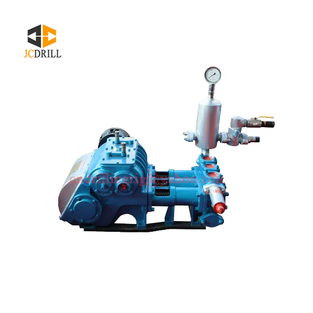
The motor directly drives V belt or chain transmission device,and then drive drilling pump. The mud charging system and pump are installed on the big skid. The high pressure mud release manifold is connected to drainage port of relief valve and mud is released into mud suction tank.
The drilling pump’s pressure lubrication system is shown in Fig. 9. In this system,through the connector holder II, the oil pump sends oil to pinion shaft nozzle, main bearing oil pipe and crosshead chamber connector holder I,then through connector seat I distribute oil to crosshead, crosshead bearing and crosshead extension rod.
Ambient temperature -20°F~+40°F (-29°C~+4°C) AGMA 250.04EP(4EP)or ASTM/ISO VG150 Oil sump Capacity:HHF-1300 pump :100US gal(379L).HHF-1600 pump :100gal(379L)
l The operator should read this manual carefully before operating the drilling pump. He can operate or maintain the equipment only when he knows well the functions and operation or maintenance of the equipment.
The discharge filter shall be installed at the other side of discharge manifold. The discharging mud go to the drilling fluid line (manifold) after filtering.
The welded suction desurger should be installed in front of all valves in suction line. The flange type suction desurger should be connected directly to inlet flange of pump suction manifold.
10.1.4.5 Watch the change for lubrication pressure, water supply of spraying pump and pump discharge pressure. If any abnormity exists, inspect and repair them timely.
10.1.2.3 Charge pump can be started in advance or together with drilling pump. It is forbidden to start drilling pump earlier than charge pump starting at any time.
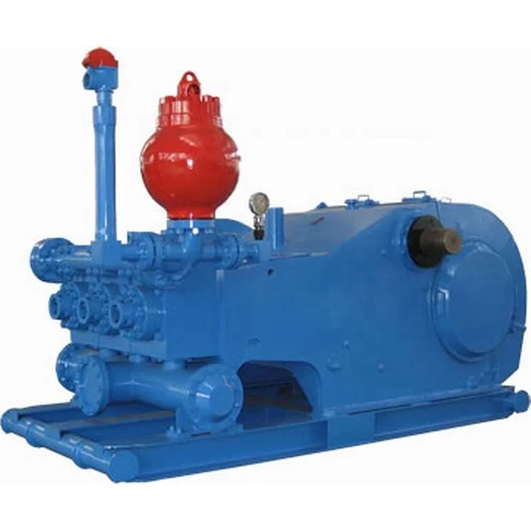
The drilling pump mainly consists of two portion, power end and fluid end (see Fig. 1). The power end includes pinion shaft, crankshaft, connecting rod, crosshead sliding block device. It can supply power to fluid end and change the rotary motion to reciprocating motion. With the power from the power end, the piston of
(2)Check Belt pulley centers’ alignment Check the belt pulley’s alignment after installing and tensioning V belt. It is required to make two belt pulley’s end faces coplanarity, allowable error not bigger than 2mm. 9.2.3.2 Chain transmission (1)Check Chain wheel’s alignment Check the sprocket’s alignment after installation. It is required to make two chain wheels’ end faces coplanarity, allowable error not bigger than 2mm. After the chain wheel installation meet requirements, install the chain. (2)Lubrication of transmission chain As an independent system, in chain transmission device of drilling pump, chain lubrication system
Safety warning:When any of mechanical and electric parts of drilling pump are running, all safety device should be in normal and effective status, include protection of AC VF motor for cooling blower faults accidently, pressure alarm of lubrication system, motor power-off protection of mud charging system. The matching between the relief valve’s limiting pressure and liner diameter, the discharge dampener inflating pressure and the related requirements etc should be checked and confirmed every shift.
Fig. 11 Pressure lubrication with mechanical driven oil pump As shown in Fig. 11,the pinion shaft drives the gear oil pump to run through v belt, and supply pressure lube for drilling pump lubrication.
10.1.1.4 Check if all valves of mud pipelines are at “on” or “off” positions before starting. 10.1.1.5 Check if the inflating pressure of discharge dampener reaches the specified value ≤4.5MPa (650psi). Caution:Only nitrogen or air can be inflated into the bladder of discharge dampener. Flammable or explosive gas such as oxygen and hydrogen are strictly forbidden. 10.1.1.6 Check if the relief valve and pressure gauge are complete and sensitive, and if the preset of relief valves is correct.
Safety warning:For any preserved pump, no matter being used at well site or transported from factory, it is necessary to be checked before put into operation. Make sure every part of pump is available and in good condition.
13 Special tools along with HHF-1300/1600 drilling pump delivery .................................................... 38 14 Spare parts along with HHF-1300/1600 drilling pump delivery ........................................................ 39 15 Recommended spare parts list ............................................................................................................ 40 16 Configuration content of a single pump ............................................................................................. 42
1. Mud gauge pressure drops, mud discharge decreases or no mud discharge at all 2. Mud discharge unevenly, pressure fluctuate badly, metal knocking sound in cylinder 3. Suction manifold has abnormal sound.
10.1.3.4 The pressure of mud discharge pressure gauge should be watched very carefully at pump starting. Before the mud return to ground, the operator is not allowed to leave.
10.1.2.5 Water baffle should be installed on crosshead extension rod before starting drilling pump. 10.1.2.6 The liner end cap (cover) should be installed before starting drilling pump
HHF-1300/1600 drilling pump is a horizontal, triplex, single action piston pump. As an important equipment for drilling operation, it feeds and circulates the high-pressure drilling fluid, which flushes the well bottom and crushes rocks, cools and lubricates drill- bit, and then carries cuttings (rock chips) return to the surface.
driven by the big gear ring of drilling pump. It is a must that the side of drive gear of oil pump and the side of big gear ring of drilling pump should be aligned. the mesh clearance (backlash) should be 0.0236″~ 0.0354″(0.60~0.90mm).
HHF-1300/1600 drilling pump is one of the most important equipments for rig for middle and deep depth well drilling. The parts and components of this drilling pump are designed and manufactured according to API 7K and relevant standards. It can satisfy the technological requirements for well drilling.
Install the pump on the structural member base of drilling boat or drilling platform. Shown in Fig.13 and 14, when fix pump skid with bolts, it is a must to place mats under skid for avoiding any distortion and deflection resulted to power end frame. Note, it needs full padding of pump skid before tightening skid for avoiding extra stress resulted to pump when tightening bolts. The mat’s width is required to be not less than the width of runner flange of skid. Its length is not less than 12″ (305mm). When integral installation is adopted for power unit or electric motor to pump skid, the pump must be fixed on the skid of the t-beam with retention blocks rather than bolts. In this way, the drilling pump could be a bit “float” so as to reduce the possible deformation of the pump frame caused by the deformation of barge deck or platform.
The left and right sides of this pump are determined by looking from the power end to the fluid end. This way is also used for determining the left, middle and right sides of equipments such as crosshead, cylinder etc.
The drilling pump adopts bimetallic liner. Liners with different diameters can be selected according to different drilling conditions. The liner is fixed on cylinder block with bolts through liner thread ring and liner lock. The liner and piston and piston rod can be lift and put in or taken out from the opening on the top of frame with the help of small lifting device mounted on frame.
It is necessary to install a suction filter in natural suction pipeline. And a suction filter should be set in front of charging pump for charging suction.
Each pump has a serial number, customers need to point out specially the model and serial number when they order spare parts and inquire about the equipment.
Before installation and operation, the operator should read this manual carefully, and do installation, operation and maintenance according to the instructions in manual. If you do not know the related contents, improper installation, operation or servicing may cause human injury or/ and the equipment damage.
mud inside valve pot and liner should be drained completely and washed cleanly before storage. Lift up the fluid end,make pump tilting to power end, drain all the oil inside oil groove and oil sump, then wash them completely. After that, remove the screw plug of oil sump, install an elbow of 90° with mouth down, put on an wire net for air ventilation and preventing vapor condensation.
There is a recommended spare parts list attached to this manual for part ordering reference, if the needed parts exceed the items listed, please consult the parts list of HHF-1300/1600.
10.1.3.3 Charging suction running: before starting the charging pump, if the diaphragm desurger is used, the tyre air inflating device should be sued to charge air for suction desurger. The air charging pressure is 0.1MPa.(15 pond /inch2). The diaphragm fluctuating range should be at observation window bottom or middle point.
The compound transmission drives drilling pump through air tube clutch and cardan shaft. The mud charging system is installed alone. The high pressure mud release manifold is connected to drainage port of relief valve and mud is released into mud suction tank.
(1)Release pressure:before doing maintenance work at cylinders, liners, pitons or valves, close the valves on suction line and discharge line, open the bypass valve to mud tank ( see Fig. 17, item 2). Only in this way can the pressure in cylinders be released, and avoid danger at opening valve pot cover and dismantling liner.
10.1.1.2 Open the top view hole cap of pump, add enough lubrication oil into pinion bearing oil groove and crosshead oil groove to ensure sufficient lubrication of all friction surfaces before operation.
Fig. 12 Pressure lubrication with electrical oil pump As shown in Fig. 12,the electrical motor drives the gear oil pump to run, and supply pressure lubrication oil to drilling pump. Attention:Before starting the drilling pump, it is a must to start electrical lubrication oil pump first to ensure full lubrication of all mechanical movement parts before work. 5.2.4 Lubrication oil type We recommend strongly that, you prefer to adopt extreme pressure (EP), non-corrosive and anti-foaming gear oil as follows: Ambient temperature +30°F~+155°F (-1°C~+68°C) AGMA 250.04EP(6EP)or ASTM/ISO VG320 Ambient temperature 0°F~+80°F (-18°C~+27°C) AGMA 250.04EP(5EP)or ASTM/ISO VG220
The lubrication oil pump has two installation modes of “Built-in mode” and “outside mode” for user to choose. If the user does not request specially, the mode “built-in” shall be used generally, no matter what mode adopted, the internal lubrication piping is same.
The splash lubrication system of drilling pump is independent to the pressure lubrication system. In splash lubrication system,the big gear ring brings oil up from oil sump, after the oiled big and small gears are meshed, the oil is squeezed out and splashed into each oil channel on frame to lubricate pinion gear shaft bearing and crosshead bearing and guide plate.(See Fig. 8)
The drilling pump can adopt natural suction or charging suction. The pipeline for natural suction should be short and the shorter the better. It is the best that it has no elbow. The size of pipeline should be the same as that of pump suction port at least ( it should be bigger if it is longer than 6 feet). The pipelines for charging suction can be made to be any bending shape needed. And the charging pump should have bypass pipeline. The drilling pump can keep working in a natural suction way once the charging pump fails or is in servicing.
5.2.1 Pressure lubrication with “built-in” oil pump As shown in Fig.10,install the oil pump in the chamber of frame, and the drive gear of oil pump is
The unitized drilling pump includes drilling pump, drive and transmission device, mud charging system, high pressure mud release manifold and big skid.
The housing is a box type weldment of steel plates, after stress relief treatment, rough and finish machining, the housing is formed. It is the base part of drilling pump. All components of drilling pump are installed into it. Oil sump and lubrication oil pipeline are set inside the housing to supply lubrication oil for gear, bearing, crosshead etc. A small lifting device with capacity of 500 kg is installed on housing for lifting liner. 4.1.2 Pinion shaft assembly
The relief valve shall be installed in front of the shut-off valve to prevent pump damage from suddenly starting while the shut-off valve is closed. The release line of relief valve can only be guided into mud suction tank. It can’t be connected to mud suction line.
10.1.3.6 The pressure of lubrication system should be 0.035~0.103MPa.(5-15psi) after mud pump starting, and the oil level should meet requirements. After starting, check the oil level if it is below the lowest mark, add oil immediately.
The unitized drilling pump directly driven by diesel engine mainly includes drilling pump, diesel engine, cardan shaft ,V belt drive device etc. the diesel engine can also directly drive V belt transmission device to run drilling pump. The mud charging system is installed alone. The high pressure mud release manifold is connected to drainage port of relief valve and mud is released into mud suction tank.
9 Drilling pump installation..................................................................................................................... 17 9.1 Installation foundation................................................................................................................. 17 9.2 Installation ................................................................................................................................... 18
(2)Inspect the working condition of liner and piston, a little mud leakage is allowable. If leakage is huge, it needs to inspect the abrasion of piston and liner inner hole. If the mud leakage excesses normal limit, the liner and piston should be replaced.
10.1.2.2 The liner spray pump can be started in advance or together with drilling pump. It is forbidden to start drilling pump earlier than spray pump starting at any time. For spraying lubrication of liner and piston, spraying system should adopt different coolants under different drilling conditions. Note: if water is the basic fluid content for coolants, preservatives (such as emulsified oil or motor oil)should be added in it for corrosion protection of parts.
A wide variety of hhf 1600 mud pump options are available to you, You can also choose from new, hhf 1600 mud pump,as well as from energy & mining, farms, and restaurant hhf 1600 mud pump,And whether hhf 1600 mud pump is provided, {2}, or {3}.

1 The cylinder (block) (fluid end) of HHF-1300/1600 and FB-1300/1600 can be interchanged, but the start place of screw hole of 12x1-14UNS-2B is different (place for wear ring connection),, 2 The clamp assembly of piston rod of FB-1300/1600mud pump can be used for HHF-1300/1600mud pump, contrarily, The clamp assembly of piston rod of HHF-1300/1600 mud pump can not be used for FB-1300/1600mud pump. (because the clamp assembly of HHF-1300/1600 has no thread to connect spray line
If you are surveying for a recognized China mud pump parts for F 1000 F 1600 F 1600L or HHF 1600 HHF 1600L Manufacturer that has speciallized in Industrial Supplies, then Oilman Group LTD is the best option. The plant of Oilman Group LTD is placed in Chengdu Sichuan China. Oilman Group LTD is a well-known corporation in China that is operating in large scale market. Oilman Group LTD Facts Name: Jack Yue

Mud Pump Pulsation Dampener is usually installed on the discharge line to reduce the fluctuation of pressure and displacement of the drilling mud pump.
Mud Pump Pulsation Dampener is a pneumatic device built into the outflow line of each UUD pump to dampen the pressure fluctuations resulting from the action of the pump. Although presented as a surge tank, this device is really a device that can be tuned to greatly diminish the output pulsations transmitted downstream from the mud pump. Unfortunately, the effectiveness of the pulsation dampener is a function of both output pump pressure and frequency of the pump pulsations.

The Baoji/Bomco F1000 Triplex mud pump has a max. working pressure of 5,000PSI and a 6-3/4" liner size. This model is the first choice for the medium and deep dr... More Info
The Baoji/Bomco F1600HL Triplex mud pump has a max. working pressure of 7,5000PSI and a displacement of 46.5L/S with 6" liner size. This model is the f... More Info
Mud Pumps - Mud Pump Parts & Complete Units: Liners, Pistons, Rubbers, Rods, Valves, Seats, Springs, Inserts (Bean, BJ, CAT, EMSCO, Ellis Williams, FMC, Failing, GASO, Gardner Denver... More Info
Mud Pumps - Mud Pump Parts & Complete Units: Liners, Pistons, Rubbers, Rods, Valves, Seats, Springs, Inserts (Bean, BJ, CAT, EMSCO, Ellis Williams, FMC, Failing, GASO, Gardner Denver... More Info
Mud Pumps - Emsco/Bomco 1600 Mud Pump, Unitized 1600 Mud Pump Powered by Two GE 752 Motors Charging Pump, Liner Flush Pump, Relief Valve, Mud Gauge, Etc. ....Call For Price More Info
Mud Pumps - Mud Pump Parts & Complete Units: Liners, Pistons, Rubbers, Rods, Valves, Seats, Springs, Inserts (Bean, BJ, CAT, EMSCO, Ellis Williams, FMC, Failing, GASO, Gardner Denver... More Info
Mud Pumps - Mud Pump Parts & Complete Units: Liners, Pistons, Rubbers, Rods, Valves, Seats, Springs, Inserts (Bean, BJ, CAT, EMSCO, Ellis Williams, FMC, Failing, GASO, Gardner Denver... More Info
Mud Pumps - Mud Pump Parts & Complete Units: Liners, Pistons, Rubbers, Rods, Valves, Seats, Springs, Inserts (Bean, BJ, CAT, EMSCO, Ellis Williams, FMC, Failing, GASO, Gardner Denver... More Info
Mud Pumps - Mud Pump Parts & Complete Units: Liners, Pistons, Rubbers, Rods, Valves, Seats, Springs, Inserts (Bean, BJ, CAT, EMSCO, Ellis Williams, FMC, Failing, GASO, Gardner Denver... More Info
Mud Pumps - Mud Pump Parts & Complete Units: Liners, Pistons, Rubbers, Rods, Valves, Seats, Springs, Inserts (Bean, BJ, CAT, EMSCO, Ellis Williams, FMC, Failing, GASO, Gardner Denver... More Info
Mud Pumps - Mud Pump Parts & Complete Units: Liners, Pistons, Rubbers, Rods, Valves, Seats, Springs, Inserts (Bean, BJ, CAT, EMSCO, Ellis Williams, FMC, Failing, GASO, Gardner Denver... More Info
Mud Pumps - 1 - Rebuilt Gardner Denver PZ-9 Mud Pump Package, New Caterpillar C-27, 1050 HP diesel engine. Belt-driven. comes with pulsation dampener, discharge block, precharge, li... More Info
Mud Pumps - 1 of 3 used Gardner Denver PZ-8 triplex mud pumps. This would be a good rebuildable core. We also have new, rebuilt and good used pumps and packages available for sale ... More Info
Mud Pumps - Mud Pump Parts & Complete Units: Liners, Pistons, Rubbers, Rods, Valves, Seats, Springs, Inserts (Bean, BJ, CAT, EMSCO, Ellis Williams, FMC, Failing, GASO, Gardner Denver... More Info


 8613371530291