
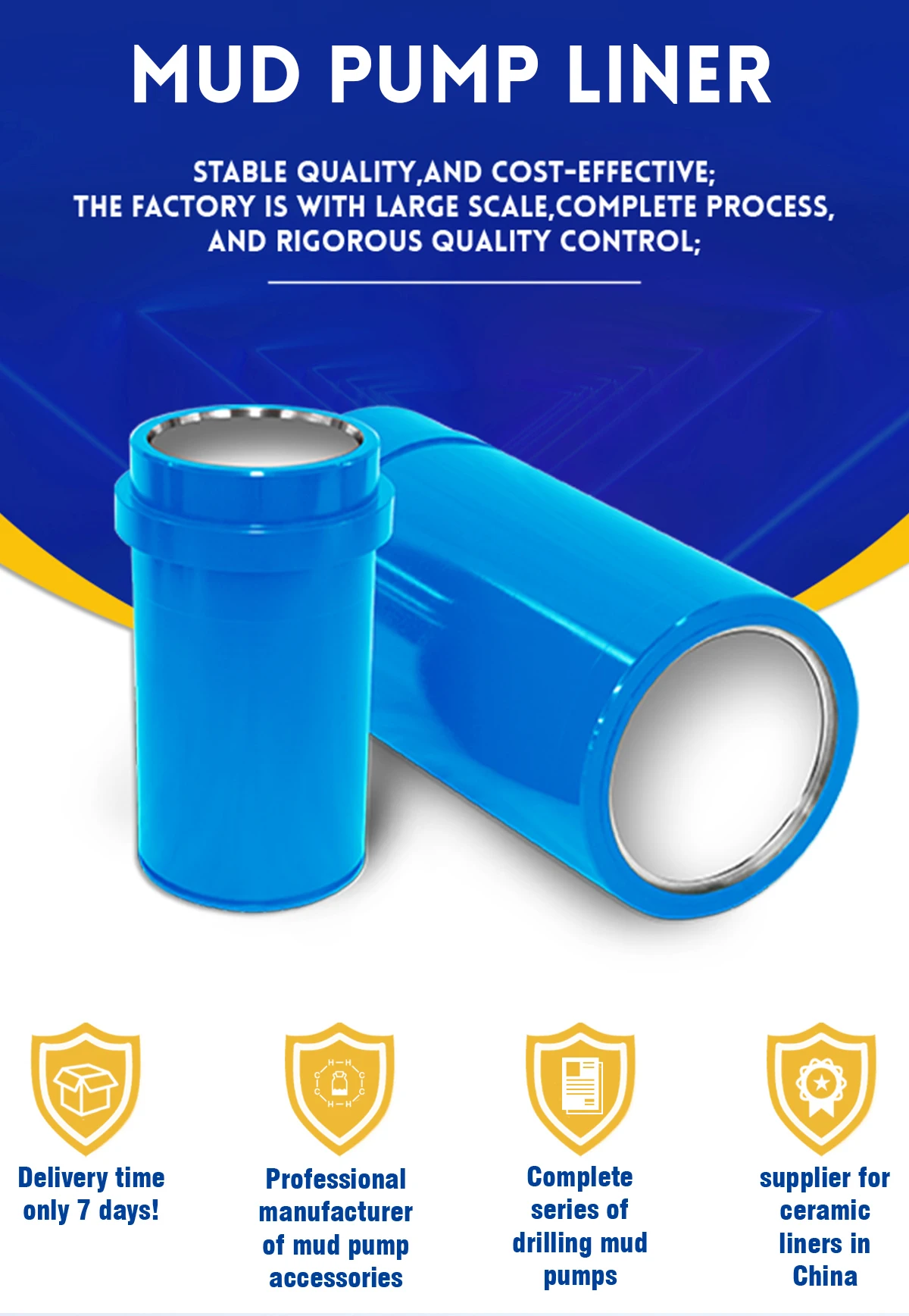
mud pump liner size free sample

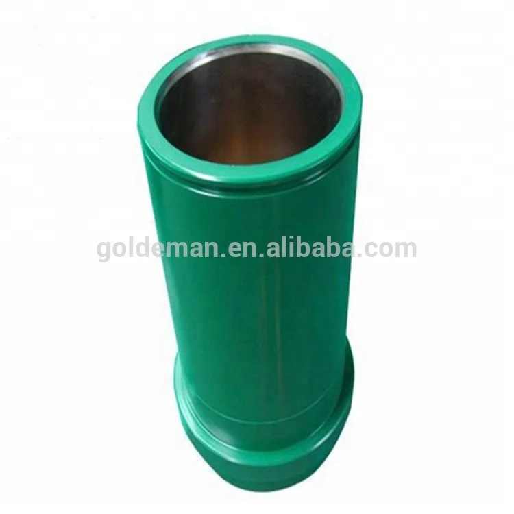
2) Production Process: The bi-metal cylinder Liner of our company combined with the advantages of abrasion hot-forging out liner and anti-corrosion high chrome inner liner. The out liner is made of high quality carbon steel by hot pressing forming. Its tensile strength is over 900000psi. The inner liner is made of high-chromium alloy by centrifugal casting.All the Double Metallic Liners and Ceramic Liners available for mud pump models can be supplied, such as following ones:
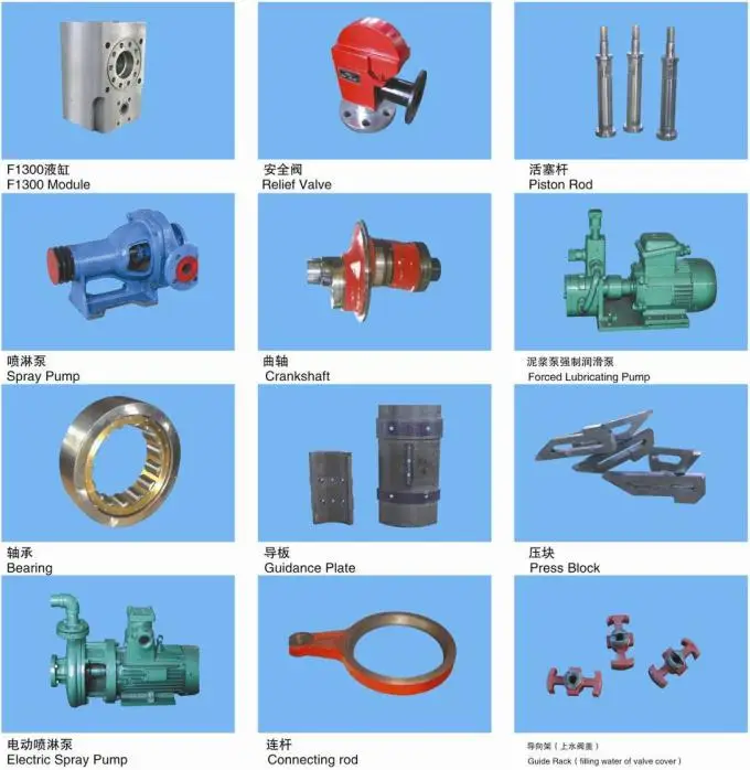
Lake Petro can supply various mud pump expendable parts, including power end assembly, fluid end assembly and its spare parts, which can be easily matched & exchanged with some international famous mud pump brand, such as parts for 3NB series Pump, F series Pump, PZ series Pump, HBRS Pump, BOMCO Pump, EMSCO Pump, NOV P Series Pump, IDECO Pump, etc.
1155 mud pump liner products are offered for sale by suppliers on Alibaba.comAbout 55% % of these are mud pump, 7%% are mining machine parts, and 3%% are other oil field equipments.
A wide variety of mud pump liner options are available to you, You can also choose from oil well, mud pump liner,as well as from carbon steel, chromium, and iron mud pump liner, and whether mud pump liner is moulding, bending, or cutting.
Rig pump output, normally in volume per stroke, of mud pumps on the rig is one of important figures that we really need to know because we will use pump out put figures to calculate many parameters such as bottom up strokes, wash out depth, tracking drilling fluid, etc. In this post, you will learn how to calculate pump out put for triplex pump and duplex pump in bothOilfield and Metric Unit.
Oil and Gas drilling process - Pupm output for Triplex and Duplex pumpsTriplex Pump Formula 1 PO, bbl/stk = 0.000243 x ( in) E.xample: Determine the pump output, bbl/stk, at 100% efficiency for a 7" by 12". triplex pump: PO @ 100%,= 0.000243 x 7 x12 PO @ 100% = 0.142884bbl/stk Adjust the pump output for 95% efficiency: Decimal equivalent = 95 + 100 = 0.95 PO @ 95% = 0.142884bbl/stk x 0.95 PO @ 95% = 0.13574bbl/stk Formula 2 PO, gpm = [3(D x 0.7854)S]0.00411 x SPM where D = liner diameter, in. S = stroke length, in. SPM = strokes per minute Determine the pump output, gpm, for a 7" by 12". triplex pump at 80 strokes per minute: PO, gpm = [3(7 x 0.7854) 1210.00411 x 80 PO, gpm = 1385.4456 x 0.00411 x 80 PO = 455.5 gpm
Example:Duplex Pump Formula 1 0.000324 x (liner diameter, in) x ( stroke lengh, in) = ________ bbl/stk -0.000162 x (rod diameter, in) x ( stroke lengh, in) = ________ bbl/stk Pump out put @ 100% eff = ________bbl/stk Example: Determine the output, bbl/stk, of a 5 1/2" by 14" duplex pump at 100% efficiency. Rod diameter = 2.0": 0.000324 x 5.5 x 14 = 0.137214bbl/stk -0.000162 x 2.0 x 14 = 0.009072bbl/stk Pump output @ 100% eff. = 0.128142bbl/stk Adjust pump output for 85% efficiency: Decimal equivalent = 85 100 = 0.85 PO@85%)= 0.128142bbl/stk x 0.85 PO@ 85% = 0.10892bbl/stk Formula 2
PO. bbl/stk = 0.000162 x S[2(D) - d] where S = stroke length, in. D = liner diameter, in. d = rod diameter, in. Example: Determine the output, bbl/stk, of a 5 1/2". by 14". duplex pump @ 100% efficiency. Rod diameter = 2.0in.: PO@100%=0.000162 x 14 x [ 2 (5.5) - 2 ] PO @ 100%)= 0.000162 x 14 x 56.5 PO@ 100%)= 0.128142bbl/stk Adjust pump output for 85% efficiency: PO@85%,= 0.128142bb/stkx 0.85 PO@8.5%= 0.10892bbl/stk Metric calculation Pump output, liter/min = pump output. liter/stk x pump speed, spm. S.I. units calculation Pump output, m/min = pump output, liter/stk x pump speed, spm. Mud Pumps Mud pumps drive the mud around the drilling system. Depending on liner size availability they can be set up to provide high pressure and low flow rate, or low pressure and high flow rate. Analysis of the application and running the Drill Bits hydraulics program will indicate which liners to recommend. Finding the specification of the mud pumps allows flow rate to be calculated from pump stroke rate, SPM. Information requiredo Pump manufacturer o Number of pumps o Liner size and gallons per revolution Weight As a drill bit cutting structure wears more weight will be required to achieve the same RoP in a homogenous formation. PDC wear flats, worn inserts and worn milled tooth teeth will make the bit drill less efficiently. Increase weight in increments of 2,000lbs approx. In general, weight should be applied before excessive rotary speed so that the cutting structure maintains a significant depth of cut to stabilise the bit and prevent whirl. If downhole weight measurements are available they can be used in combination with surface measurements to gain a more accurate representation of what is happening in the well bore.
The 2,200-hp mud pump for offshore applications is a single-acting reciprocating triplex mud pump designed for high fluid flow rates, even at low operating speeds, and with a long stroke design. These features reduce the number of load reversals in critical components and increase the life of fluid end parts.
The pump’s critical components are strategically placed to make maintenance and inspection far easier and safer. The two-piece, quick-release piston rod lets you remove the piston without disturbing the liner, minimizing downtime when you’re replacing fluid parts.

NOV 12-P-160 Mud Pump is rated at 1600 input horsepower (1193 kw) at 120 strokes per minute, with a 12-inch (304.8 mm) stroke. Multiple liner sizes allow pressures and volumes to handle circulation requirements in deep drilling applications.
Flexibility: Compact engineering provides higher efficiency in less space. The NOV 12-P-160 Triplex Mud Pump light weight and flexible design make it easily adaptable to a variety of rig configurations. This provides flexibility as drilling requirements and conditions change.
Fluid End Modules: NOV offers a choice of fluid end modules and valve covers for every P Series pump model to select the fluid end module that exactly matches drilling requirements. All pump models can be equipped with either the standard or premium forged, two-piece interchangeable fluid modules

Kverneland, Hege, Kyllingstad, Åge, and Magne Moe. "Development and Performance Testing of the Hex Mud Pump." Paper presented at the SPE/IADC Drilling Conference, Amsterdam, Netherlands, February 2003. doi: https://doi.org/10.2118/79831-MS
As usual, winter — or the slow season — is the time most drillers take the time to maintain their equipment in order to get ready for the peak season. One of the main parts that usually needs attention is the mud pump. Sometimes, it is just a set of swabs to bring it up to snuff, but often, tearing it down and inspecting the parts may reveal that other things need attention. For instance, liners. I can usually run three sets of swabs before it is time to change the liner. New liners and swabs last a good long time. The second set of swabs lasts less, and by the time you put in your third set of swabs, it’s time to order new liners. Probably rods too. It’s not always necessary to change pistons when you change swabs. Sometimes just the rubber needs to be changed, saving money. How do you tell? There is a small groove around the outside of the piston. As it wears, the groove will disappear and it’s time for a new piston.
The wear groove on a piston can be a good indicator of the general health of your pump. If the wear is pretty even all around, chances are the pump is in pretty good shape. But if you see wear on one side only, that is a clue to dig deeper. Uneven wear is a sign that the rods are not stroking at the exact angle that they were designed to, which is parallel to the liner. So, it’s time to look at the gear end. Or as some folks call it, “the expensive end.”
The wear groove on a piston can be a good indicator of the general health of your pump. If the wear is pretty even all around, chances are the pump is in pretty good shape. But if you see wear on one side only, that is a clue to dig deeper.
After you get the cover off the gear end, the first thing to look at will be the oil. It needs to be fairly clean, with no drill mud in it. Also look for metal. Some brass is to be expected, but if you put a magnet in the oil and come back later and it has more than a little metal on it, it gets more serious. The brass in the big end of the connecting rod is a wearable part. It is made to be replaced at intervals — usually years. The most common source of metal is from the bull and pinion gears. They transmit the power to the mud. If you look at the pinion gear closely, you will find that it wears faster than the bull gear. This is for two reasons. First, it is at the top of the pump and may not receive adequate lubrication. The second reason is wear. All the teeth on both the bull and pinion gears receive the same amount of wear, but the bull gear has many more teeth to spread the wear. That is why, with a well maintained pump, the bull gear will outlast the pinion gear three, four or even five times. Pinion gears aren’t too expensive and are fairly easy to change.
This process is fairly straightforward machine work, but over the years, I have discovered a trick that will bring a rebuild up to “better than new.” When you tear a pump down, did you ever notice that there is about 1-inch of liner on each end that has no wear? This is because the swab never gets to it. If it has wear closer to one end than the other, your rods are out of adjustment. The trick is to offset grind the journals. I usually offset mine about ¼-inch. This gives me a ½-inch increase in the stroke without weakening the gear end. This turns a 5x6 pump into a 5½x6 pump. More fluid equals better holes. I adjust the rods to the right length to keep from running out the end of the liner, and enjoy the benefits.
Other than age, the problem I have seen with journal wear is improper lubrication. Smaller pumps rely on splash lubrication. This means that as the crank strokes, the rods pick up oil and it lubricates the crank journals. If your gear end is full of drill mud due to bad packing, it’s going to eat your pump. If the oil is clean, but still shows crank wear, you need to look at the oil you are using.
Oil that is too thick will not be very well picked up and won’t find its way into the oil holes in the brass to lubricate the journals. I’ve seen drillers that, when their pump starts knocking, they switch to a heavier weight oil. This actually makes the problem worse. In my experience, factory specified gear end oil is designed for warmer climates. As you move north, it needs to be lighter to do its job. Several drillers I know in the Northern Tier and Canada run 30 weight in their pumps. In Georgia, I run 40W90. Seems to work well.

Internal cavities of metal objects frequently require a cladding, or a coating, that is more corrosion, oxidation and/or wear resistant than the metal object itself. This need may arise in some cases due to high temperatures created within the cavity, exposure to a corrosive or abrasive liquid, and/or to rubbing action of an internal machine member such as a piston. An example of such a metal object is the liners in mud pumps used in oil field drilling. A mud pump is a part of the oil or gas well drilling fluid circulating system, one of five major components of a rotary drilling operation. The other components are the drill string and bit, the hoisting system, the power plant and the blowout prevention system.
Drilling fluid, usually called the "mud", in most cases consists of a mixture of water, various special chemicals including corrosion inhibitors and solid particles such as Barite to increase its density. Such fluid is continuously circulated down the inside of the drill pipe, through the bottom of the bit and back up the annular space between the drill pipe and the hole. The driving force is provided by a mud pump.
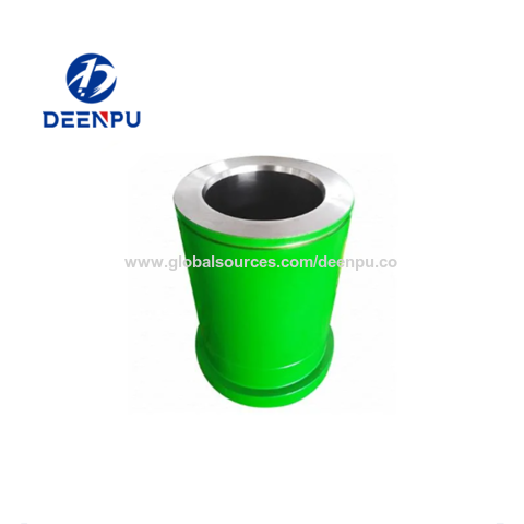
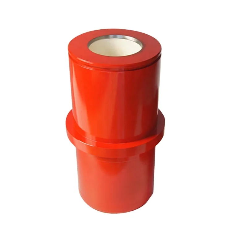
A mud pump liner is basically a heavy wall pipe section with one or two retaining rings at its outer diameter. It is the wear resistance of the inner surface that determines the liner service life. Consequently, the internal surface of the liner is desirably clad with a wear resistant material. The internal cladding layer is subjected to sliding wear by the rubber piston which can wear and cause metallic structure supporting the rubber to contact the liner cladding, thus accelerating the wear process. The cladding material is also subjected to corrosion from the drilling fluid, and metal fatigue caused by cyclic loading, especially at areas where the direction of the piston motion suddenly changes, Further, micro regions of cladding may experience sudden pressurization and depressurization. These operating conditions impose stringent metallurgical requirements on the cladding materials. An ideal cladding material should, therefore, possess high hardness and high resistance to corrosion, impact and metal fatiuge. Such properties are desirably achieved by a uniform, fine grained microstructure, which has been the goal of pump liner makers of many years.
The outer, heavy wall portions of the commercially available mud pump liners typically consist of either a carbon steel, or a low alloy steel; and the liner cladding is, in most cases, a cast sleeve of iron--28% chromium alloy. The sleeve can be centrifugally cast into the steel pipe section or cast separately as a pipe, and shrink fitted into the outer pipe section, then machined to a smooth finish. These manufacturing procedures are lengthy and costly, while providing only a cast metal microstructure which is known to be chemically nonuniform, since in castings the solidification process results in natural segregation of the elemental species contained in the alloy. Furthermore, the cladding thicknesses are kept undesirably large to allow casting processes to be used. The claddings within metallic objects other than pump liners can be similarly characterized and most likely be prone to the same deficiencies.
A cladding layer made of powder metals consolidated to near 100% density and bonded to the outer steel shell appears to provide the most desirable metallurgical microstructure, due to its chemical uniformity and high ductility emanating from its fine grain size. Existing methods of application of such powder metal layers, however, are grossly inadequate in that they either produce a porous, oxide contaminated layer which is only mechanically bonded to the outer shell as in sprayed coatings, or they are superficially and only mechanically bonded to the outer shell as in brazed-on coatings. For these, and other reasons, present powder metallurgy techiniques for such products have not been considered adequate.
It is a major object of the invention to provide a powder metal cladding method and apparatus for cladding the internal cavity surface of metal liners and objects, overcoming the above problem and deficiencies. In addition, the invention provides various material combinations for the production of pump liners and internally clad pipe segments for use with oilfield mud pump fluids. There are many other products that can benefit from this processing technique.
As will appear, pressurization of the grain is typically carried out by transmitting force to the grain along a primary axis, the layer extending about that axis and spaced therefrom, whereby force is transmitted by the grain away from the axis and against said layer. To this end, the method contemplates providing a die having a first chamber receiving said object, the die having a second chamber containing grain communicating with grain in the cavity, pressurizing of the grain in the cavity being carried out by pressurizing the grain in the second chamber, as for example by transmitting pressure from the grain in the second chamber to only a medial portion of the grain in the first chamber everywhere spaced from said layer. Further, the metal object is typically cylindrical, the layer being applied on an internal cylindrical surface of said object, the latter for example comprising a mud pump liner.
Referring first to FIG. 1, and alloy steel mud pump liner 10 comprises an elongated tube 11 having an outer flange 12 on one end portion. The tube axis appears at 13, and the tube inner cylindrical surface at 14. Tube 11 may be considered to represent other metal objects having interior surfaces (as at 14) facing internal cavities 15.
Referring to FIG. 2, the next step in the process is to place the liner containing the green now lightly sintered layer 11a within a step die 19 where the liner fits into the large cavity (i.e. first chamber 19) in the die as shown in the figure, and having inner cylindrical walls 19a and 19b. The die second chamber 20 throat diameter D1 should be equal to or smaller than the "green" internal diameter D2 of the mud pump liner 11a. This assures relatively shearless pressing of the green powder metal cladding 11a under largely lateral pressure during the pressurizing step. Chamber 20 has a bore 20a.
As seen in FIG. 3, pressurization takes place in a press 21 after filling both the die and the pump liner cavities with a refractory powder 22 already at a temperature near or above the consolidation temperature of the cladding powder. The pressure from ram 23 is transmitted to the liner by the horizontal forces created within the refractory powder grains. In this regard, the second chamber 20 is in axial alignment with the first chamber 19, the second chamber having a cross section less than the cross section of the first chamber, whereby pressure is transmitted from the grain 22a in the second chamber to only a medial portion of the grain 22b in the first chamber which is everywhere spaced from layer 11a. Therefore, lateral pressurizing of the grain in the cavity 19 is affected by grain pressurized longitudinally in the second chamber, and no destructive shear is transmitted to layer 11a.
The process, while remaining basically the same, may have some variations. For example, there may be an insulating material positioned between the part (the pump liner in FIG. 2) and the die to reduce heat loss before pressing.


 8613371530291