
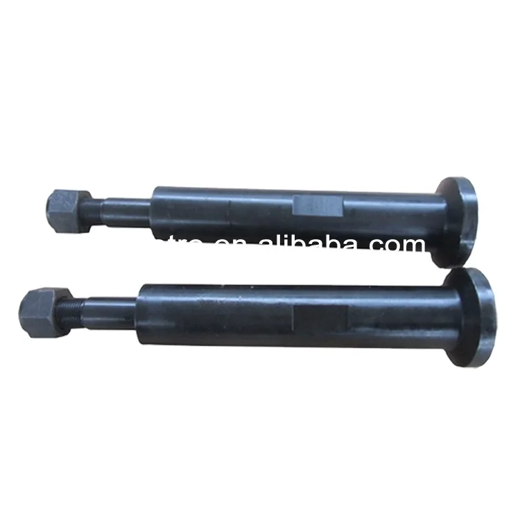
mud pump piston rod free sample

A wide variety of mud pump piston rod options are available to you, such as 1 year, not available and 2 years.You can also choose from new, mud pump piston rod,as well as from energy & mining, construction works , and machinery repair shops mud pump piston rod, and whether mud pump piston rod is 1.5 years, 6 months, or unavailable.
It is known to use pumps to provide drilling mud under pressure in the drilling of wells. Pressurized drilling mud is delivered down a hollow drill string as the well is being drilled to carry away cuttings up the annulus surrounding the drill string to ground level. Such drilling operations are well known to those skilled in the art.
Prior art pumps can use a motor to turn a crankshaft or “pump shaft” to convert rotary motion to a reciprocating motion. The pump shaft moves a connecting rod coupled to a crosshead that moves within a fixed crosshead slide to provide this conversion. The crosshead is coupled to a “pony rod” that, in turn, is coupled to a piston rod that provides the pumping motion in a pump module, as well known to those skilled in the art.
The above-mentioned mechanical arrangement can be multiplied so that a multitude or plurality of pump modules can be operated from a single pump shaft. The outputs of each pump module can be coupled to a common manifold from which pressurized drilling mud can be provided to the drill string. By coupling the pump module outputs to a common manifold, the pulsing of the pressure of the drilling mud can be reduced or smoothed out, this being a problem well known to those skilled in the art. The disadvantage of this mechanical arrangement is the size and complexity of the components involved to provide a multi-module pump.
It is also known in the oil and gas industry to drill horizontal wells. These are wells that are initially drilled vertically and, with the use of directional drilling equipment as well known to those skilled in the art, the direction of drilled well becomes horizontal or parallel with the ground surface. It is known to drill horizontal wells 5000 to 7500 feet in length or more. To do so requires the use of “mud motors”, motors that are powered by the delivery of highly pressurized drilling mud pumped through the drill string so as to enable the turning of the drill bit. It is also known that to drill such wells, drilling operators will use at least two or more conventional mud pumps powered by 1000 horsepower or more motors. Each mud pump is housed in its own pump house and occupies space at the drilling site. As each additional pump house increases the number of structures at a drilling site, the number of truckloads required to deliver the necessary equipment to a drilling site also increases. All this additional equipment and number of truckloads to deliver the equipment add cost to the drilling of the well.
It is, therefore, desirable to provide a pump that can convert rotary motion to reciprocating motion without having to use connecting rods, crossheads, crosshead slides and pony rods to reduce its size, complexity and cost to manufacture. It is also desirable to provide a mud pump that is compact in size but can deliver pressurized mud at a volume equivalent to two or more conventional mud pumps.
A pump is provided that comprises a pump shaft having at least one eccentric lobe that is substantially circular. A motor is used to provide the rotational power to the pump shaft. In one embodiment, the motor can be coupled directly to the pump shaft. In another embodiment, a transmission can be used between the motor and the pump shaft to reduce the angular speed of the rotational power provided to the pump shaft. In a representative embodiment, a one or two-stage gear transmission can be used. In a further embodiment, the motor can be a 3-phase AC motor controlled by a variable frequency drive mechanism to control the speed of the motor.
In one embodiment of the pump, the eccentric lobe can be rotatably disposed within a connecting rod having a substantially circular opening to receive the lobe at one end with the other end rotatably pinned to a slide configured to move in a horizontal and linear manner. In one embodiment, the slide can be slidably disposed within a pair of slide support plates that constrains the slide to move in a linearly and horizontal or side-to-side manner. In one embodiment, slide-bearing mechanisms can be disposed between the slide and the support plates so that the slide can move side-to-side with minimal friction. In a representative embodiment, the slide-bearing mechanism can further comprise means for adjusting a loading force on the slide-bearing mechanism against the slide so that the slide is further constrained to horizontal and linear movement.
As the lobe rotates within the connecting rod opening, the connecting rod slide can move up and down thereby moving the slide linearly and horizontally between the slide support plates. As the slide frame moves side to side, it can move a piston rod in and out to operate a pump module. By virtue of this configuration, the slide can have a piston rod operatively coupled to one or both opposing sides of the slide. Therefore, a single slide can operate one or two pump modules at the same time. In a further embodiment, the pump shaft can comprise a plurality of eccentric lobes thereby allowing a plurality of slides to be operated by the lobes and, hence, a plurality of pump modules to be operated from a single rotating pump shaft.
Broadly stated, in some embodiments, a mud pump is provided, comprising: a frame; at least one pump module disposed on the frame, the at least one pump module comprising an inlet port and an outlet port; a pump shaft rotatably disposed in the frame for receiving rotational power from a motor, the pump shaft having at least one substantially circular eccentric lobe disposed thereon, the centre of the at least one eccentric lobe displaced or offset from the longitudinal axis of the pump shaft; at least one slide disposed in the frame, the at least one slide operatively configured to move linearly side-to-side within the frame; at least one piston rod assembly operatively coupling the at least one slide to the at least one pump module; and a connecting rod comprising first and second ends operating coupling the pump shaft to the at least one slide, the first end rotatably disposed on the at least one eccentric lobe, the second end rotatably pinned to the at least one slide whereby rotation of the pump shaft causes the slide to move side-to-side that, in turn, causes the at least one piston rod assembly to operate the at least one pump module.
Broadly stated, in some embodiments, a mud pump is provided, comprising: a platform; a lattice frame disposed on the platform; at least one pump module disposed on the frame, the at least one pump module comprising an inlet port and an outlet port; a pump shaft rotatably disposed in the frame for receiving rotational power from a motor, the pump shaft having at least one substantially circular eccentric lobe disposed thereon, the centre of the at least one eccentric lobe displaced or offset from the longitudinal axis of the pump shaft; a motor operatively coupled to the pump shaft, the motor disposed on the platform; at least one slide disposed in the frame, the at least one slide operatively configured to move linearly side-to-side within the frame; at least one piston rod assembly operatively coupling the at least one slide to the at least one pump module; and a connecting rod comprising first and second ends operating coupling the pump shaft to the at least one slide, the first end rotatably disposed on the at least one eccentric lobe, the second end rotatably pinned to the at least one slide whereby rotation of the pump shaft causes the slide to move side-to-side that, in turn, causes the at least one piston rod assembly to operate the at least one pump module.
FIG. 7 is a perspective view depicting the frame of the mud pump of FIG. 1 showing only the slides, the slide bearings, the slide bearing support plates and the piston assemblies;
Referring to FIGS. 1 to 13, one embodiment of a mud pump is illustrated. In this embodiment, mud pump 10 can comprise lattice frame 18 and pump modules 24 mounted thereon. Frame 18 can further comprise mounting tabs 14 for attaching mud pump 10 to a platform, to a skid or to a pump house.
For the purposes of this specification, and as shown specifically in the figures, each pump module 24 can comprise inlet port 25, outlet port 35, top access port 37 and side access port 36. Pump module 24, as illustrated, can be any suitable pump module that is readily available to the mud pump industry and is well known to those skilled in the art. As shown in FIG. 1, pump module 24 is shown as a singular device having three pump units disposed therein. It is obvious to those skilled in the art that pump module 24 can comprise one or more pump units use in combination. Representative examples of pump module 24 are pump modules having an 800 horsepower rating as manufactured by Continental Emsco in the U.S.A. or their equivalent. Such pumps have interchangeable liners of different diameters whereby the volume of mud handled by a pump module per pump cycle can be adjusted upwards or downwards depending on the diameter of the liner. Generally speaking, the smaller the volume per pump module, the greater the pressure the mud can be pumped at.
Referring to FIG. 1, mud pump 10 is shown having cover 20 disposed on top of lattice frame 18. Input shaft 12 can be connected to a motor (not shown) to provide rotational input power to mud pump 10. In some embodiments, an internal combustion motor can be used to provide rotational input power to mud pump 10. In other embodiments, an electric motor of suitable power rating can be used. In further embodiments, a variable frequency drive mechanism (not shown) as well known to those skilled in the art can be used to control the electrical power provided to the electric motor thereby controlling the rotational speed the motor operates at to supply rotational input power to mud pump 10.
In one embodiment, mud pump 10 can comprise transmission 22 to couple shaft 12 to the operating components of mud pump 10. Transmission 22 can be a single-stage or dual-stage gear transmission to reduce the rotational speed of input shaft 12 to the required rotational speed for proper operation of pump shaft 30 rotatably disposed in mud pump 10. In other embodiments, transmission 22 can comprise a planetary gear transmission. In further embodiments, transmission 22 can comprise helical gears. In yet other embodiments, transmission 22 can comprise spur gears. Intake manifold 52, comprising inlet 54, is shown attached to pump module inlet ports 25. Outlet manifold 58, comprising couplers 62 and end caps 66, is shown attached to pump module outlet ports 35. In one embodiment, frame 18 can comprise return lines 68 that provide communication from galleys 38 to reservoir 70. When in operation, lubricating oils are used to lubricate the moving components of mud pump 10. These oils will collect in galleys 38 and return to reservoir 70 through return lines 68 to be re-circulated through mud pump 10.
Referring to FIG. 2, a rear elevation view of mud pump 10 is shown. In this figure, piston rod support bushings 31 are shown disposed on sidewalls 19 of frame 18. Piston liners 26 are shown disposed between pump modules 24 and support bushings 31. Couplers 41 can be used to couple liners 26 to support bushings 31. As noted above, liners 26 can be comprised of various diameters depending on the volume and the pressure drilling mud is to be produced by mud pump 10.
Referring to FIGS. 3 and 4, front views of mud pump 10 are shown. In this embodiment, pump modules 24 are shown with outlet ports 35 exposed having no output manifold attached thereon to show valve mechanism 39 disposed therein. In one embodiment, pump module 24 can comprise “sucker-cup” pump mechanisms as well known to those skilled in the art. In the illustrated embodiment, an output manifold (not shown) can be attached to the shown outlet ports 35 to collect drilling mud pumped by pump module 24, in addition to outlet manifold 58 shown in FIGS. 1 and 2, or it can be capped with a cover (not shown). Input ports 25 can be coupled together with intake manifold 52 that directs drilling mud into pump modules 24. In one embodiment, coolant pump 34 can be used to circulate coolant through piston liners 26 and oil pump 32 can be used to pump lubricating oil through support bushings 31 to lubricate the moving components therein, as described in more detail below and as shown in FIG. 13.
Referring to FIGS. 5 and 6, front cross-section views of mud pump 10 are shown revealing the internal components of the embodiment shown therein. In this embodiment, pump shaft 30 rotates as a result of input rotational power applied to input shaft 12 that is operatively coupled to pump shaft 30 via transmission 22 as shown in FIG. 4. In one embodiment, pump shaft 30 can comprise eccentric 80 disposed thereon and affixed thereto with pin 82. Rotatably disposed on eccentric 80 is connecting rod 84. In another embodiment, eccentric bearing 83 is disposed between eccentric 80 and connecting rod 84. In a further embodiment, connecting rod 84 is rotatably pinned to sidewall 28b(and sidewall 28aas shown in FIGS. 8 and 9) of slide 28 via pin 86. In yet another embodiment, bearing 85 can be disposed between pin 86 and connecting rod 84. In FIG. 5, eccentric 80 is shown rotating clockwise thereby moving connecting rod 84 upwards and to the right in this figure. In so doing, slide 28 is being pushed to the right. In one embodiment, slide 28 is disposed between upper support plate 44 and lower support plate 46 to help keep slide 28 moving in a horizontal linear path, and to resist the bending moment caused by the rotation of pump shaft 30 and eccentric 80. In another embodiment, upper slide bearing 43 can be disposed between upper plate 44 and slide 28, and lower slide bearing 45 can be disposed between lower plate 46 and slide 28 as a means to reduce the friction between slide 28 and upper and lower plates 44 and 46 as slide 28 moves side-to-side.
As slide 28 moves to the right, it pushes piston rod 27aand, hence, piston 40ato the right in liner 26ato push fluids in pump chamber 42aout through valve 39aoto outlet ports 35 (not shown) and outlet manifold 58 (not shown). In so doing, piston rod 27balso pulls piston 40bin liner 26bto the right thereby drawing in fluid through valve 39bifrom intake manifold 52.
In FIG. 6, eccentric 80 is shown rotated further clockwise (from FIG. 5) thereby moving connecting rod 84 downward and to the left. In so doing, piston 40ais being pulled to the left thereby drawing in fluid into pump chamber 42athrough valve 39aifrom intake manifold 52 while piston 40bis pushed to the left thereby pushing fluid out of pump chamber 42bthrough valve 39boto outlet ports 35 (not shown) and outlet manifold 58 (not shown). In this figure, the connecting rods 84 of two adjacent stages rising above the top of frame 18.
Referring to FIG. 7, mud pump 10 is shown without pump modules 24, cover 22, piston liners 26, pump shaft 30, slides 28 and connecting rods 84. In this illustrated embodiment, frame sidewalls 19 are visible as are removable caps 17, which are configured hold pump shaft 30 in place in frame 18. Also visible are piston rods 27, rod support bushings 31, couplers 41 and pistons 40. In one embodiment, mud pump 10 can comprise means for applying a loading force to upper support plates 44 to keep slide 28 confined to a horizontally linear range of motions. In some embodiments, these means can comprise a plurality of setscrew rails 48 disposed on frame 18 near sidewalls 19 and disposed on caps 17. In further embodiments, setscrew rails 48 can comprise a plurality of setscrews 47 threadably attached to and through said setscrew rails. Setscrews 47 can be tightened to apply forces to various locations on upper support plates 44 whereby the loading force applied to upper support plates can be adjusted at each location of setscrews 47 to ensure that slide 28 is constrained to horizontal linear movement. While the illustrated embodiment shows setscrews 47 as being manually adjustable for applying force to slide 28, it is obvious to those skilled in the art that mud pump 10 can comprise further means for monitoring the movement of slides 28 and for automatically adjusting setscrews 47 with electro-mechanical servo motors, or the like, so that setscrews 47 are dynamically adjusted in real-time to ensure that proper force is being applied to slide 28 at all times to keep its movement linearly horizontal.
Referring to FIG. 8, the mud pump 10 of FIG. 7 is now shown with frame 18 removed to reveal slides 28. In some embodiments, each slide 28 can comprise a pair of substantially parallel spaced-apart sidewalls 28aand 28b, as shown in FIGS. 8, 9 and 10. In this embodiment, slides 28 can comprise openings 29 disposed through sidewalls 28aand 28bfor pump shaft 30 (not shown) to pass through and pin openings 88 disposed through sidewalls 28aand 28bthat are configured to receive connecting rod pins 86 (not shown). In some embodiments, mud pump 10 can further comprise one or more eccentric rods 49 disposed beneath lower support plates 46 for applying upwards force thereto for ensuring that slide 28 is constrained to horizontal linear movement. This is also shown in FIGS. 9, 10, 11 and 12. In some embodiments, eccentric rods 49 can be rotated or adjusted and then set into position by turning rod adjusters 50. While the illustrated embodiment shows eccentric rods 49 as being manually adjustable for applying force to slide 28, it is obvious to those skilled in the art that mud pump 10 can comprise further means for monitoring the movement of slides 28 and for automatically adjusting eccentric rods 49 with electro-mechanical servo motors, or the like, operatively coupled to rod adjusters 50 so that eccentric rods 49 are dynamically adjusted in real-time to ensure that proper force is being applied to slide 28 at all times to keep its movement linearly horizontal.
Referring to FIG. 13, a cross-section view is shown of the internal pumping mechanism of mud pump 10. In some embodiments, piston rod 27 can be coupled to slide 28 by threading piston rod 27 into threaded opening 91 disposed on slide 28. In other embodiments, piston rod 27 can be further secured with lock nut 101 threaded on piston rod 27 and tightened against slide 28. In yet further embodiments, piston rod stud 92 can be disposed in an opening disposed through piston rod 27 and secured to slide 28 in threaded opening 93. In some embodiments, piston rod stud 92 can further comprise flange 95 that can rest against shoulder 94 disposed within piston rod 27. Piston rod stud 92 can also serve as means for mounting piston 40 and piston retaining caps 96 and 97 thereon. Nut 98 can be used to secure piston 40 and caps 96 and 97 on piston rod stud 92.
In some embodiments, mud pump 10 can comprise means for circulating coolant in piston liner 26 behind piston 40 to prevent overheating of the mechanism when in operation. As shown in FIG. 13, coolant can be pumped by coolant pump 34 (as shown in FIG. 4) into liner chamber 106 through coolant inlet 102 via lines, hoses or piping (not shown). Coolant can the flow through, and circulate within, chamber 106 and then exit through coolant outlet 104. Lines, hoses and piping (not shown) can be coupled to outlet 104 so that the heated coolant can be collected, cooled and re-circulated. In other embodiments, inlet 102 and outlet 104 can further comprise one-way valves, such as ball-valves as one example obvious to those skilled in the art, such that coolant can be drawn into chamber 106 through inlet 102 as piston 40 is moving towards pump module 24 (not shown), and then expelled from chamber 106 through outlet 104 and piston 40 is moving away from pump module 24.
In some embodiments, mud pump 10 can comprise means for circulating lubricating oil to piston rod 27 as it reciprocates back and forth through support bushing 31. As shown in FIG. 13, lubricating oil can be pumped by oil pump 32 (as shown in FIG. 4) into oil inlet 108 where it can flow into annulus 110 between piston rod 27 and support bushing 31 thereby maintaining a layer of lubricating oil therebetween. Oil can then flow out of annulus 110 into galleys 38 (as shown in FIG. 1) where the oil can be collected and re-circulated. In other embodiments, barrier seals 99 and ice-breaker wear band 100 can be disposed between piston rod 27 and support bushing 31 as sealing means to separate and isolate chamber 106 from annulus 110 so that coolant does not intermingle with and contaminate the lubricating oil, and vice-versa.
In the embodiments illustrated the figures herein, there are three slides 28 shown, each coupled to two pump modules 24 thereby resulting in the operation of six pump modules. It is obvious to those skilled in the art that fewer or more slides mechanisms can be implemented to either decrease or increase the number of pump modules that can be operated. It is also obvious to those skilled in the art that a slide frame can be releasably coupled to a single piston rod to, therefore, operate a single pump module.
Referring to FIG. 6, pump shaft 30 is shown turning three connecting rods 84. This necessarily requires pump shaft 30 having three eccentric lobes 80. In this configuration, the lobes can be displaced nominally 120° apart from each other such that the lobes can be substantially spaced equally apart around the circumference of pump shaft 30. In embodiments where pump shaft 30 comprises two eccentric lobes 80, the lobes can be displaced nominally 180° apart. In other embodiments where pump shaft 30 comprises two lobes 80, one lobe 80 can be displaced 178° from the other lobe 80 so that pump shaft 30 can more easily turn from a dead stop. In other embodiments where additional eccentric lobes are disposed on pump shaft 30, the lobes can be substantially spaced equally apart on pump shaft 30. For example, for a four-lobe shaft, each lobe 80 can be displaced 90° nominally from each other lobe 80. If five lobes are disposed on pump shaft 30, the lobes can be displaced nominally 72° apart on pump shaft 30. For six lobes disposed on pump shaft 30, the lobes can be displaced nominally 60° apart, and so on.
In operation, mud can be supplied to inlet 54 on intake manifold 52 from an external pump (not shown) drawing mud from a mud tank (not shown) as well known to those skilled in the art. As slides 28 operate pump modules 24, mud is drawn into pump modules 24 from intake manifold 52 and pumped out of pump modules 24 into outlet manifold 58 via outlet manifold couplers 62 disposed between pump modules 24 and outlet manifold 58. The pumped mud can exit outlet manifold 58 via outlet 60 that can be connected to a mud delivery pipe and/or hose for use on a drilling rig (not shown) as well known to those skilled in the art. In one embodiment, the diameter of inlet 54 and the pipe that make up intake manifold 52 can be nominally ten inches whereas the diameter of outlet and the pipe that make up outlet manifold 58 can be nominally four inches. In another embodiment, outlet manifold 58 can comprise couplings (not shown) for connection with a pressure gauge to provide a visual indication of the pressure of the mud being pumped and/or a pressure relief valve to provide means to limit the pressure of the mud being pumped by mud pump 50. It is obvious to those skilled in the art that the diameters of inlet 54, intake manifold 52, outlet manifold 58 or outlet 60 can be increased or decreased depending on the volume and pressure of drilling mud required in the drilling of a well.
In operation, it is expected that mud pump 10 can operate up to 65 revolutions per minute using a 1000 horsepower motor, which translates up to 130 pump module strokes per minute per slide frame mechanism given that each slide frame can be coupled to two pump modules. It is also anticipated that mud pump 10 can pump up to 800 gallons or 4 cubic meters of drilling mud per minute. Using 7-inch liners in the pump modules, it is expected that mud pump 10 can pump mud up to 1500 pounds per square inch in pressure. It is also expected that mud pump 10 would weigh approximately 45,000 pounds and deliver the equivalent volume and pressure of drilling mud as a conventional mud pump powered by a 1600 horsepower motor weighing up to 120,000 pounds.
Referring to FIG. 14, mud pump 10 is shown positioned in pump house 56, a structure used to house mud pumps at drilling sites. Access to mud pump 10 is done through doorways 64. In this configuration, mud pump 10, with electric motor 87 coupled to mud pump 10 via transmission 22, is positioned “lengthwise” in pump house 56. Referring to FIG. 15, the combination of mud pump 10 and motor 87 is shown in pump house 56 rotated 90 degrees. The compactness of mud pump 10 can allow it to be installed in this manner in pump house 56 whereby access to the inlet and outlet to mud pump 10 is through doorway 64. In addition, more than one mud pump 10 can be installed in pump house 56 thereby reducing the number of pump houses required at a drilling site if the well being drilled requires a volume of pressurized drilling mud greater than what one mud pump 50 can provide.

Claims. (Cl. 287-111) This invention has to do with reciprocating parts connecting a prime mover with an oil well mud pump, and particularly with improved means for connecting a crank driven intermediate rod or pony rod reciprocated by a prime mover with a mud pump piston rod. Primarily, the invention is directed to the objective of providing an improved coupling means which greatly simplifies the operation of coupling and uncoupling these rods.
The usual means for connecting pony and piston rods in end-to-end relation for reciprocating movement consists of a threaded connection to which the end of the piston rod is externally threaded to engage an internally threaded bore in the pony rod. One disadvantage resulting from the use of this type of connection lies in the necessity for rotating the piston rod a number of times in order to couple or uncouple it from the pony rod. The piston rod is heavy and difficult to rotate, and any movement of the mud pump piston is made extremely diicult by reason of the presence of the abrasive mud between the piston and cylinder walls. For this reason the operation of coupling or uncoupling the two rods is laborious and time consuming.
In accordance with the present invention, it is now made possible to quickly join together pony and mud pump piston rods in such a way that the latter need not be rotated more than a very small amount during connection; and yet the invention retains the advantageous rod aligning and connecting features provided by a threaded coupling. This invention contemplates the use of an improved split bushing which is easily and quickly joined to end portions of the pony and piston rods. Shoulders are formed on the split bushing and on the two shafts to transmit reciprocating movement of the pony rod to the piston rod, and the split bushing halves are held in shaft interengaging position by a nut.
The invention also enables the improved split bushing to be used in combination with existing piston rods, since the bushing is threaded to engage the threaded ends of these rods.
Fig. 2 is an enlarged sectional View illustrating in detail the connection means joining the pony shaft of the prime mover with the piston shaft of the mud pump; and
Shaft means connecting a prime mover 11 and a mud pump 12 is shown in Fig. l of the drawings. The prime mover includes a housing 13, end plate 14, and shaft bearings 15 joined to the end plate, and means driven by a crank, not shown, for reciprocating a pair of pony rods 13. The pony rods extend through the bearings 15 and toward the mud pump 12.
The mud pump 12 includes housing 20, end plate 21, and bearings 22 joined to the end plate, and encloses a ice 2 pair of cylinders 23 containing pistons 24. Piston shafts 25 extend through the bearings 22 toward the pony shafts 18, and it will be understood that on reciprocation of the pistons 24, circulating iluid or mud is drawn into and- Each piston rod 25 is joined to its corresponding pony rod 18 by the connection means 26. As shown in Fig. 2, the connectionr means includes a coupling device 27 for joining the extension 28 of each pony or intermediate rod to the end portion 29 of each portion rod. An annular sloped shoulder 30 is formed on a ange 31 formed on extension 28, the shoulder dening"a section ot" a dove-tail connection. Also mounted onl pony shaft 18 is a rubber ring 32 having tapered wall 33 in engagement with the tapered section 34 of the rod 18 to keep sand and other foreign matter out of contact with the internal portions of the connection means 26. The end portion 29 of piston rod 25 is externally threaded, and a knurled section 36 is formed upon rod 25 adjacent end portion 29. The knurled section 36 enables the rod to be gripped by the jaws of a Wrench and rotated. It will be noted that piston rod end portion 29 is of standard design, and need not be altered for use in conjunction with the improved shaft connection means 26.
The coupling device 27 includes a pair of semicylin drical sections or split halves 37 which together form Each section 37 includes a sloped a split bushing. shoulder 38 formed at one end of a recess 39 contained in that section, the shoulder 38 defining the complementary section of the dovetail connection mentioned above. The inner surface of each bushing section 37 is threaded near the opposite end of the section to engage the threaded end 29 of the piston shaft. A hexagonal nut 39 is also mounted on the threaded end portion 29 of piston shaft 25. The nut has a counterbore recess 50 with a recessed and sloped end Wall 40 which engages the sloped end face 41 of each of the sections 37, the counterbore 50 closely receiving"and overlapping the end portions of the sections 37 to maintain them in engagement with the threaded portion 29 of the piston shaft, and to lock the assembly in position to prevent unscrewing and loosening thereof.
In order to couple the pony or intermediate rod 18 to the piston rod 25, the lock nut 39 is screwed on the threaded end 29 of rod 25 as far as it will go. Next, the threaded ends of the split halves or sections 27 are pried apart sufciently to allow the piston rod 25 to be pushed between the halves, and the end 42 of the rod is jammed against the end 43 of the intermediate rod extension 28. The split halves are then brought together to clamp around the external threads on the end 29 of the piston rod, and if necessary the halves may be rotated slightly to match their threads with the piston rod threads. Following this, the lock nut 39 is screwed against the split halves and hand-tightened, making sure that the counterbore recess on the lock nut receives the split halves to prevent loosening of the assembly. Finally, the piston rod is irmly tightened against the extension 28 and the lock nut 39 tightened against the split halves 27.
To uncouple the pony and piston rods, the lock nut is loosened from the split halves, and the piston rod is backed off from the extension 28 about one turn. The split halves may then be pried apart to permit the piston rod to be pulled completely away from the pony rod.
1. The combination, comprising prime mover having a pony rod and means through which the rod projects, said rod having a cylindrical surface sized for reciprocation Patented Dec. 23, 1958 through said means and a shoulder facing axially oppositely from the rod end, a mud pump piston rod having a threaded shank axially aligned with the pony rod and abuttingY said end thereof, a split bushing spanningsaid shoulder and-shank and including another shoulder and threads respectively engaging said ponyA rod shoulderand the. shank threads to releasably hold saidrods inl end abutting.v relation whereby axial movement of the pony` rod may, be transmitted tothe piston rod,- said split bushing` being within a cylindrical axial projection of said pony rod surface so as to be receivable within said means during rod reciprocation, and a nut mounted on said shank-and having a recess receiving the end of said bushing to prevent disengagement ofsaid shoulders and threads, said nut being rotatable on the shank away from the bushing to free it for separation from the shank permitting release of the piston rod. from connection to the v ponyrod.y
2. The combination, comprising prime mover having a pony rod and means through which the rod projects, said rod having a cylindrical surface sized for reciprocation through said means and an undercut external shoulder facing axially oppositely from the rod end, a mud pump piston rod having an externally threaded shank axially aligned with the pony rod and abutting said end thereof, a split bushing spanning said shoulder and shank and including an undercut internal shoulder and internal threads respectively engaging said pony rod shoulder and the shank threads to releasably hold said rods in end abutting relation and said shoulders against separation whereby axial movement ofthe. pony rod may be transmitted to the piston rod, said split bushing being within a cylindrical axial projection of said pony rod surface so as to be receivable within said means during rod reciprocation, and a nut mounted on said shank and having a-recess receiving the end of said bushing to prevent disengagement of said threads, said nut being rotatable on the shank away from the bushing to free it for separation from theshankpermitting release of the piston rod from connection to the pony rod.
4. The combination, comprising prime mover having a pony rod and means through which the rod projects, said rod having a cylindrical surface sized for reciprocation through said means and aV reduced diameter end portion carrying an undercut ilange facing oppositely from the rod end, a mud pump piston rod having an externally threaded shank axially aligned with thepony rod: and abutting the end thereof, a split bushing spanning said flange and shank and including an undercut collar and internal threads respectively engaging said flange and said shank threads to releasably hold the rods in end abutting relation and said ange and collar against separation whereby axialmovement of the pony rod may be transmitted to the piston rod, said split bushing being within a cylindrical axial projection of said pony rod surface so as to be receivable withinsaid means during rod reciprocation, and a" nut mounted on said shank andV having a recess receiving the end of said bushing to prevent disengagement of said threads, said nut being rotatable on the shank away from the bushing to free it for separation from the shank permitting release of the piston rod from connection to the pony rod.
5. The invention as defined in claim 4, in which said pony rod has `an annular shoulder intersecting said cylindrical surface and spaced from the end of said bushing,
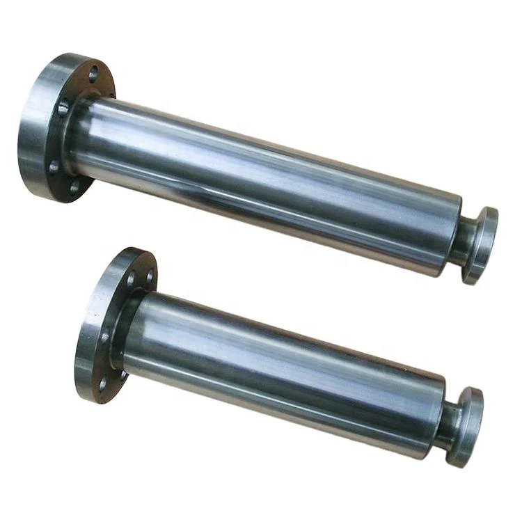
The 2,200-hp mud pump for offshore applications is a single-acting reciprocating triplex mud pump designed for high fluid flow rates, even at low operating speeds, and with a long stroke design. These features reduce the number of load reversals in critical components and increase the life of fluid end parts.
The pump’s critical components are strategically placed to make maintenance and inspection far easier and safer. The two-piece, quick-release piston rod lets you remove the piston without disturbing the liner, minimizing downtime when you’re replacing fluid parts.

TECHNICAL FIELD OF THE INVENTION The present invention relates generally to piston seals for mud pumps and more particularly to a replaceable piston seal. Still more particularly, the present invention relates to a durable polymeric piston seal constructed with very small tolerances so as to provide a precise interference fit with the corresponding liner.
Slush or mud pumps are commonly used for pumping drilling mud in connection with oil well drilling operations. Because of the need to pump the drilling mud through several thousand feet of drill pipe, such pumps typically operate at high pressures. Moreover, it is necessary for the mud to emerge from the drill bit downhole at a relatively high velocity in order to provide lubrication and cooling to the bit and to provide a vehicle for the removal of drill cuttings from the earth formation being drilled. Lastly, the pressure generated by the mud pump contributes to the total downhole pressure, which is used to prevent well blowouts.
The pistons and cylinders used for such mud pumps are susceptible to a high degree of wear during use because the drilling mud is relatively dense and has a high proportion of suspended abrasive solids. As the pump cylinder becomes worn, the small annular space between the piston and the cylinder wall increases substantially and sometimes irregularly. For these reasons, the seal design for such pumps is critical.
The high pressure abrasive environment in which the pumps must operate is especially deleterious to the seals since considerable friction forces are generated, and since the hydraulic pressures encountered during operation force the seal into the annular space between the cylinder wall and the piston. In some instances, the frictional forces may even detach the seal from the piston. In these instances, the edges of the seal can become damaged very quickly by the cutting or tearing action that occurs as a result of piston movement. Another problem with conventional mud pump seals is that they do not adequately "wipe" the
Attempts have been made to retain the seal in the piston so as to resist this frictional force. One conventional solution to this problem has been use of a metallic seal retainer which is disposed over the seal body and retained in place by snap rings. One disadvantage of this solution, however, is that the additional seal retaining element and its snap rings render the overall piston construction more expensive. A further disadvantage is that the seal is made somewhat less flexible and resilient than it would otherwise be, thus decreasing its ability to wipe the cylinder wall effectively. Another conventional solution to the sealing problem comprises including a seal retaining ring or reinforcement in the seal itself. In this case, the retaining ring or reinforcement is molded into the seal material. As with the external retaining ring, this solution decreases the flexibility of the seal and increases its cost of manufacture.
It is common to incorporate the foregoing seals into piston heads wherein the seal is permanently affixed to the piston head. This is disadvantageous because the seal tends to wear much faster than the piston head, resulting in waste and unnecessary expense when the whole piston head has to be replaced because of wear to the seal member. It is therefore desirable to provide a piston seal that is removable from the piston head and thus can be replaced without requiring replacement of the whole piston head. The nature of the mud pump operating environment makes it difficult to effectively address these issues. It is, therefore, desired to develop a new and improved replaceable seal for a reciprocating mud pump piston that overcomes the foregoing difficulties while providing better wear properties and more advantageous overall results.
BRIEF SUMMARY OF THE INVENTION The present invention comprises a new and improved replaceable seal for a reciprocating mud pump piston. The present seal does not require any external seal retaining means and is free from any incorporated seal retainer or reinforcement. The present seal is manufactured to precise specifications that minimize play between the seal, piston head and cylinder and also compensate for the slight deformation of the seal member that occurs when the seal member is demolded and cured.
BRIEF DESCRIPTION OF THE DRAWINGS For an introduction to the detailed description of the preferred embodiments of the invention, reference will now be made to the accompanying drawings, wherein:
Figure 3 is a cross sectional view of the sealing member of Figure 2 mounted on a piston head in a cylinder. DETAILED DESCRIPTION OF THE PREFERRED EMBODIMENTS
Referring initially to Figure 1, a typical prior-art mud pump piston assembly comprises a piston head 10 and a sealing device or seal 15 therefor slidably received in a piston cylinder 12. Piston head 10 comprises a generally cylindrical body having a flange 11 extending therefrom. Piston head 10 is typically made of steel, such as AISI 4140. Seal 15 is friction fit on piston head 10 and abuts flange 11. Seal 15 comprises an elastomeric sealing section 14 and a heel section 13. These sections are either integrally formed or bonded together. Heel section 13 is typically made from a stack of several layers of rubber- impregnated fabric, which give it a higher modulus of elasticity than the elastomeric sealing section 14. In prior art mud pumps, the heel section 13, which is stiffer than the elastomeric sealing section, resists extrusion into the gap between the cylinder and piston flange to some extent. However, heel section 13 is still forced into the gap under the influence of the hydrostatic pressure in locations where wear occurs. Reference numeral 18 designates a portion of heel section 14 that has been extruded into the gap 20 between the flange 11 and the cylinder 12. Both elastomeric sealing section 14 and heel section 13 make intimate contact with the cylinder 12. Seal 15 is held in place by a retaining ring 16 and a snap ring 17, which hold seal 15 in place and permit replacement thereof. Easy replacement of seals is a desirable feature for a mud pump, since seals typically wear out long before the other mud pump components and must be replaced in order to continue pumping operations. The direction of travel of piston 10 is shown by arrow 19. The direction of the hydrostatic pressure force exerted by the working fluid of the pump is shown by arrows 21. This force axially compresses elastomeric sealing section 14 and heel section 13 and radially expands these sections against the cylinder wall.
Referring now to Figure 3, the seal 22 of Figure 2 is shown mounted on a piston head in a cylinder. It can be seen that sealing lip 24 is compressed radially and conforms to the inside of 12. In addition, in order to enable seal 22 to be used without a reinforced heel section, piston head 10 is manufactured to extremely tight tolerances. In particular, it has been discovered that the life of seal 22 can be greatly prolonged by ensuring that play between flange 11 and cylinder 12 is minimized at the outset. Thus, the average width of the annular gap 25 between flange 11 and cylinder 12 is much smaller than in previously known devices. In this regard, it is preferred that the difference between the outside diameter of flange 11 as manufactured and the inside diameter of cylinder 12 as manufactured be less than 0.010 inches, and more preferably less than 0.008 inches. By way of example, flange 11 of a 6 inch piston is preferably about 0.002 to 0.010 inch smaller than the associated bore.
As can be seen in the Figures, the sealing lip 24 of seal 22 is preferably somewhat larger than the nominal inside diameter of the cylinder 12. Again by way of example, for a piston having a nominal diameter of six inches, sealing lip 24 preferably has a diameter of about 6.25 inches. Thus, in one preferred embodiment, diameters are as follows: for metal flange 11, df = 5.990; for cylinder 12, inside diameter idi = 6.000; for seal lip 23, ds = 6.250; and for heel 24, dh = 5.990.
Although the invention is described with particular reference to a pump piston used with slush or mud pumps, it will be recognized that certain features thereof may be used or adopted to use in other types of reciprocating pumps. Likewise it will be understood that various modification can be made to the present seal without departing from the scope of the invention. For example, the relative dimensions of various parts, the materials from which the seal is made, and other parameters can be varied, so long as the seal retains the advantages discussed herein.

This section is intended to introduce the reader to various aspects of art that may be related to various aspects of the presently described embodiments. This discussion is believed to be helpful in providing the reader with background information to facilitate a better understanding of the various aspects of the present embodiments. Accordingly, it should be understood that these statements are to be read in this light, and not as admissions of prior art.
In order to meet consumer and industrial demand for natural resources, companies often invest significant amounts of time and money in finding and extracting oil, natural gas, and other subterranean resources from the earth. Particularly, once a desired subterranean resource such as oil or natural gas is discovered, drilling and production systems are often employed to access and extract the resource. These systems may be located onshore or offshore depending on the location of a desired resource. Further, such systems generally include a wellhead assembly mounted on a well through which the resource is accessed or extracted. These wellhead assemblies may include a wide variety of components, such as various casings, valves, pumps, fluid conduits, and the like, that control drilling or extraction operations.
As will be appreciated, drilling and production operations employ fluids referred to as mud or drilling fluids to provide lubrication and cooling of the drill bit, clear away cuttings, and maintain desired hydrostatic pressure during operations. Mud can include all types of water-based, oil-based, or synthetic-based drilling fluids. Mud pumps can be used to move large quantities of mud from surface tanks, down thousands of feet of drill pipe, out nozzles in the bit, back up the annulus, and back to the tanks. Operations come to a halt if the mud pumps fail, and thus, reliability under harsh conditions, using all types of abrasive fluids, is of utmost commercial interest.
Some embodiments of the present disclosure generally relate to a self-aligning mud pump apparatus. In one embodiment, the self-aligning mud pump apparatus includes a housing and a rotatable crankshaft disposed in the housing. The self-aligning mud pump apparatus can include a crosshead disposed in the housing, as well as a crosshead guide disposed in the housing to constrain movement of the crosshead. The self-aligning mud pump apparatus can include a hub disposed in the housing and disposed on the crankshaft for converting a rotating motion of the crankshaft to a reciprocating motion of the crosshead via a connecting rod having a first end coupled to the hub and a second end coupled to the crosshead. The connecting rod can be coupled to the crosshead such that the connecting rod has five degrees of freedom with respect to the crosshead guide.
Certain embodiments of the present disclosure generally relate to a method for assembling self-aligning components of a pump. The method can include providing a crosshead of the pump and coupling a connecting rod to the crosshead with a first socket joint that allows three rotational degrees of freedom between the connecting rod and the crosshead. The method can also include coupling a piston to the crosshead with a second socket joint that allows three rotational degrees of freedom between the piston and the crosshead.
FIG. 6B shows a schematic of an alternative crankshaft of a mud pump such as shown in FIG. 6A in accordance with one or more implementations described herein.
FIG. 6C shows a schematic of an alternative crankshaft of a mud pump such as shown in FIG. 6A in accordance with one or more implementations described herein.
FIG. 7A shows a schematic of a modular mud pump unit that can be used alone or in combination with a mirror-image modular unit, as shown in FIG. 7B, in accordance with one or more implementations described herein.
FIG. 8A shows a partial cross-section of a crosshead and connecting rod interface of a mud pump, in accordance with one or more implementations described herein.
FIG. 8C shows a partial cross-section of a crosshead and connecting rod interface of a mud pump, in accordance with one or more implementations described herein.
FIGS. 10A-10F depict various embodiments of a plunger piston in various sealing configurations in accordance with one or more implementations described herein.
When introducing elements of various embodiments, the articles “a,” “an,” “the,” and “said” are intended to mean that there are one or more of the elements. The terms “comprising,” “including,” and “having” are intended to be inclusive and mean that there may be additional elements other than the listed elements. Moreover, any use of “top,” “bottom,” “above,” “below,” other directional terms, and variations of these terms is made for convenience, but does not require any particular orientation of the components.
The present disclosure describes a variety of design changes to mud pump kinematics and construction to result in a less rigid, more robust and reliable mud pump. In a first embodiment described in greater detail below, load balancing is achieved by spacing hubs along the crankshaft of the mud pump with the bull gears disposed opposite one another, on the outermost ends of the crankshaft adjacent to the housing. In such an embodiment, the hubs are disposed along the crankshaft between the bull gears. In a second embodiment described in greater detail below, a novel crosshead design enables connection to both connecting rod and piston, resulting in self-aligning components with at least three degrees of rotational freedom and two degrees of translational freedom. In a third embodiment described in greater detail below, the present disclosure also includes various seal and/or piston sleeve assemblies that can be applied to a plunger style piston.
Generally speaking, FIG. 1 illustrates a wellsite system in which the disclosed mud pump can be employed. The wellsite system of FIG. 1 may be onshore or offshore. In the wellsite system of FIG. 1, a borehole 11 may be formed in subsurface formations by rotary drilling using any suitable technique. A drill string 12 may be suspended within the borehole 11 and may have a bottom hole assembly 100 that includes a drill bit 105 at its lower end. A surface system of the wellsite system of FIG. 1 may include a platform and derrick assembly 10 positioned over the borehole 11, the platform and derrick assembly 10 including a rotary table 16, kelly 17, hook 18 and rotary swivel 19. The drill string 12 may be rotated by the rotary table 16, energized by any suitable means, which engages the kelly 17 at the upper end of the drill string 12. The drill string 12 may be suspended from the hook 18, attached to a traveling block (not shown), through the kelly 17 and the rotary swivel 19, which permits rotation of the drill string 12 relative to the hook 18. A top drive system could alternatively be used, which may be a top drive system well known to those of ordinary skill in the art.
In the wellsite system of FIG. 1, the surface system may also include drilling fluid 26 (also referred to as mud) stored in a pit/tank 27 at the wellsite. A pump 29 supported on a skid 28 may deliver the drilling fluid 26 to the interior of the drill string 12 via a port in the swivel 19, causing the drilling fluid to flow downwardly through the drill string 12 as indicated by the directional arrow 8. The drilling fluid 26 may exit the drill string 12 via ports in a drill bit 105, and circulate upwardly through the annulus region between the outside of the drill string 12 and the wall of the borehole 11, as indicated by the directional arrows 9. In this manner, the drilling fluid 26 lubricates the drill bit 105 and carries formation cuttings up to the surface, as the drilling fluid 26 is returned to the pit/tank 27 for recirculation. The drilling fluid 26 also serves to maintain hydrostatic pressure and prevent well collapse. The drilling fluid 26 may also be used for telemetry purposes. A bottom hole assembly 100 of the wellsite system of FIG. 1 may include logging-while-drilling (LWD) modules 120 and 120A and/or measuring-while-drilling (MWD) modules 130 and 130A, a roto-steerable system and motor 150, and the drill bit 105.
FIG. 2 shows a cutaway side view of a prior art mud pump, illustrating various components of the power assembly, the portion of the pump that converts rotational energy into reciprocating motion. A pump as shown in FIG. 2 could be used as pump 29 of FIG. 1, although many other mud pumps, including those with designs described below in accordance with certain embodiments of the present technique, could instead be used as pump 29. Pinion gears 52 along a pinion shaft 48 drive a larger gear referred to as a bull gear 42 (e.g., a helical gear or a herringbone gear), which rotates on a crankshaft 40. Pinion shaft 48 is turned by a motor (not shown). The crankshaft 40 turns to cause rotational motion of hubs 44 disposed on the crankshaft 40, each hub 44 being connected to or integrated with a connecting rod 46. By way of the connecting rods 46, the rotational motion of the crankshaft 40 (and hub 44 connected thereto) is converted into reciprocating motion. The connecting rods 46 couple to a crosshead 54 (a crosshead block and crosshead extension as shown may be referred to collectively as the crosshead 54 herein). The crosshead 54 moves translationally constrained by guide 57. Pony rods 60 connect the crosshead 54 to a piston 58. In the fluid end of the pump, each piston 58 reciprocates to move mud in and out of valves in the fluid end of the pump 29.
Using conventional mud pump designs, pumping drilling fluids at above 50% capacity and/or for longer periods of time accelerates pump failure. With any combination of the design changes described below implemented, a mud pump may be operable at a higher capacity for longer periods of time. The design changes disclosed herein include load balancing embodiments, self-aligning power assembly embodiments, and piston sealing implementations.
Turning now to FIG. 3, a load-balanced mud pump is shown. Within a housing 33, a pinion shaft 48 is disposed, supported in roller bearings 51 at each opposing end of pinion shaft 48. Pinion shaft 48 is driven by a motor (not shown). A pair of pinion gears 52 rotate on the pinion shaft 48. Pinion gears 52 engage with bull gears 42, each of which rotate on a crankshaft 40. As can be seen in FIG. 3, the bull gears 42 are positioned adjacent to the housing 33 along the crankshaft 40, and pinion gears 52 are likewise positioned adjacent to the housing 33 along the pinion shaft 48. A plurality of hubs 44 are positioned along the crankshaft 40 between the bull gears 42 without any hubs positioned between the bull gears 42 and the walls of the housing 33.
By separating the largest, heaviest gears, i.e., the bull gears 42, toward the exterior along the crankshaft, an optimized load balance is accomplished. The position of the pinion gears 52 being substantially toward the exterior along the pinion shaft 48 further contributes to the load balance of the pump overall. In other embodiments, pinion gears 42 and bull gears 52 may be positioned further away from the walls of the housing while still remaining closer to the walls of the housing than to a midpoint along the pinion shaft 48 and crankshaft 40 respectively.
Each hub 44 is integrated with a connecting rod 46 (typically a forged metal) that couples at an interface to a crosshead 54, which will be discussed in further detail below. In turn, each crosshead 54 also couples at another interface to a plunger piston 58 (shown in FIG. 9A). Crosshead 54 is constrained in direction of movement by a guide, not shown in FIG. 3, discussed further below. In the fluid end, plunger piston 58 draws mud in and out by way of inlet 59 and outlet 61. Valve pots 63 are the machine openings to the fluid end of the mud pump.
FIG. 4A shows a schematic of a mud pump in accordance with one or more implementations described herein. Motors 31 couple operatively to a series of gear wheels 32. The gear wheels 32 rotate the pinion shaft 48. Pinion shaft 48 is supported in the housing 33 by a pinion shaft roller bearing 51 in the wall of housing 33 at either end of the pinion shaft 48. The pinion gears 52 are rotatable on pinion shaft 48. Pinion gears 52 engage bull gears 42, which are rotatable on the crankshaft 40. Crankshaft 40 is supported in the housing 33 on crankshaft roller bearings 56 in the walls of housing 33 at either end of the crankshaft 40. Bull gears 42 are positioned along crankshaft 40 at opposite ends of the crankshaft 40, adjacent to the walls of housing 33. Hubs 44 are positioned along the crankshaft between the bull gears 42. In the embodiment shown, the hubs 44 are spaced about evenly across the crankshaft 40. The crankshaft 40 passes through not the center of each hub, but at a position radially offset from the center of each hub, such that the hubs 44 are out of phase relative to one another to drive the pistons. Alternatively, embodiments are envisioned in which spacing is optimized for load balancing based on the weight and/or size of each individual hub 44 and connecting rod 46. Additionally, four hubs 44 are shown in FIG. 4A, though pumps having as few as two, or as many as five, hubs for driving reciprocal motion of crossheads are likewise contemplated in the present disclosure.
FIG. 4B shows a schematic of an alternative of a mud pump in accordance with one or more implementations described herein. Motors 31 couple operatively to a series of gear wheels 32. The gear wheels 32 rotate two separate pinion shafts, denoted pinion shafts 48A and 48B in FIG. 4B. Separate pinion shafts 48 enable easier repair of pump components, as there is sufficient room to, if needed, remove each pinion shaft independently. By comparison a single longer length pinion shaft may be of such a length as to be physically difficult to remove once the pump is rigged up in limited space at a wellsite. Pinion shafts 48 are supported in the housing 33 by at least a pair of pinion shaft roller bearings 51A and 51B in the wall of housing 33 on both sides of the housing 33. In order for each pinion shaft to rotate without wobbling under weight, at least two points of mechanical support are used. Thus, a mechanical support 55 affixed to (or integrated with) the housing 33 provides support to pairs of roller bearings 51A and 51B. A pinion gear 52 is rotatable on each separate pinion shaft 48. Pinion gears 52 engage bull gears 42, each of which is rotatable on the crankshaft 40. The positioning of the bull gears 42 and hubs 44 along the crankshaft 40 are, in FIG. 4B, similar to the configuration as described with respect to FIG. 4A.
FIG. 4C shows a schematic of an alternative of a mud pump in accordance with one or more implementations described herein. Motors 31 couple operatively to a series of gear wheels 32. The gear wheels 32 rotate two separate pinion shafts 48 coupled together at a coupler 65. The coupler 65 serves two purposes. First, the coupler 65 mechanically fastens the two pinion shafts 48 to one another such that the length of the fastened pinion shafts 48 is mechanically supported. Second, the coupler 65 serves to synchronize rotation of pinion shafts 48A and 48B, allowing the pinion shafts 48A and 48B to be rotated with respect to one another during assembly for proper rotational phase difference between the hubs 44 of the two shafts to drive the pistons. By disconnecting the coupler 65, each pinion shaft 48 can be replaced independent of the other. Pinion shafts 48 are supported in the housing 33 by at least a pair of pinion shaft roller bearings, denoted 51A and 51B, in the wall of housing 33 on both sides of the housing 33. As above, in order for each pinion shaft to rotate without wobbling under weight, at least two points of mechanical support are used. Thus, mechanical support 55 affixed to (or integrated with) the housing 33 provides an anchoring point for pairs of roller bearings 51A and 51B to hold up each pinion shaft 48A and 48B. A pinion gear 52 is rotatable on each separate pinion shaft 48. Pinion gears 52 engage bull gears 42, each of which is rotatable on the crankshaft 40. The positioning of the bull gears 42 and hubs 44 along the crankshaft 40 are, in FIG. 4C, similar to the configuration as described with respect to FIG. 4A.
FIG. 5A shows a schematic of a crankshaft of a mud pump in accordance with one or more implementations described herein. The pinion shaft 48 and pinion gear 52 may be configured as in any of the embodiments described above. As can be seen in FIG. 5A, the bull gears 42 are positioned adjacent to the housing 33 along the crankshaft 40. Pinion gears 52 may likewise be positioned adjacent to the housing 33 along the pinion shaft 48. A plurality of hubs 44 are positioned along the crankshaft 40 between the bull gears 42. An optimized weight load balance is accomplished by separating the largest, heaviest gears, the bull gears 42. In the embodiment of FIG. 5A, the crankshaft 40 spans a length less than the width of the housing 33. In lieu of roller bearings 56 in the walls of the housing 33 to support the crankshaft 40, mechanical supports 62 are attached to (or integrated with) the housing 33 to support the crankshaft 40. Lubricated pads 64 affix to the mechanical supports 62 so that the crankshaft 40 rotates freely. FIG. 5B shows a cross-section of an example of a lubricated pad, as an alternative for a roller bearing, for use in the embodiment shown in FIG. 5A. The lubricated pad 64 may include a lower pad 64A and an upper pad 64B, each conformed to curve around crankshaft 40. In a preferred embodiment, the lubricated pads are offset by 30° relative to a horizontal plane running through the crankshaft 40, as shown. The surface of lower pad 64A and upper pad 64B are lubricated. Additional lubricant can be added to the surfaces in contact with the crankshaft 40 in the gap between lower pad 64A and upper pad 64B.
FIG. 6A shows a schematic of an alternative of a mud pump in accordance with one or more implementations described herein. Load balancing is achieved in the embodiment of FIG. 6A by positioning the bull gears 42 adjacent to one another, centered on the crankshaft 40 and having none of the hubs 44 positioned on the crankshaft 40 therebetween. Motors 31 couple operatively to a series of gear wheels 32. The gear wheels 32 rotate pinion shaft 48. Pinion shaft 48 is supported in the housing 33 by pinion shaft roller bearings 51 in the walls of housing 33 on both sides of the housing 33. Pinion gears 52A and 52B are rotatable on pinion shaft 48, and are positioned adjacent to one another without engaging one another. The pinion gears 52A and 52B may be helical in design, as shown in FIG. 6B. Pinion gears 52 engage bull gears 42, each of which is rotatable on the crankshaft 40. In the embodiment of FIG. 6A, the crankshaft 40 spans a length less than the width of the housing 33. In lieu of roller bearings 56 in the walls of the housing 33 to support the crankshaft 40, mechanical supports 62 are attached to or integrated with the housing 33 to brace or support the crankshaft 40, and lubricated pads 64, such as those shown in F


 8613371530291