
mud pump pony rod free sample
31 mud pump pony rod products are offered for sale by suppliers on Alibaba.comAbout 70% % of these are mud pump, 12%% are pumps, and 9%% are mining machine parts.
A wide variety of mud pump pony rod options are available to you, You can also choose from new, mud pump pony rod,as well as from energy & mining, construction works , and machinery repair shops mud pump pony rod, and whether mud pump pony rod is 1.5 years, 6 months, or 3 months.
8 pony rod for emsco mud pump products are offered for sale by suppliers on Alibaba.com, of which mud pump accounts for 75%, mining machine parts accounts for 25%.
A wide variety of pony rod for emsco mud pump options are available to you, You can also choose from new, pony rod for emsco mud pump,as well as from energy & mining, machinery repair shops, and manufacturing plant pony rod for emsco mud pump,And whether pony rod for emsco mud pump is 3 months, {2}, or {3}.

This application is a continuation of pending U.S. patent Ser. No. 12/220,876 entitled “A Reinforced Smart Mud Pump” which take priority to provisional application for patent filed Jul. 30, 2007 bearing Ser. No. 60/962,637 and is incorporated by reference herein as if fully set forth.
This invention relates generally to the field of mud pumps and more specifically to a reinforced smart mud pump. Mud pumps that use piston displacement, produce imposed forces that cause wear and tear on various pump components, including pump cross head piping, cylinders, inlet and discharge valves, seal components including piston or plunger seals, the pump cylinder block or so-called fluid end, and other components. There has been a need to provide increased longevity and performance for such pumps and to determine if deteriorations in pump performance are occurring, to analyze the source of decreased performance and to further real time control and data to monitor and in some cases change the operating characteristics before damage occurs to the pump. The use of greatly strengthened components in combination with a computer controlled system integrated with a real time monitored and controlled reset relief valve may be integrated into an oilfield application to prevent catastrophic pump failure and extend pump life.
Pump operating characteristics often have a deleterious effect on pump performance. For example, delayed valve closing and sealing can result in loss of volumetric efficiency. Factors affecting pump valve performance include fluid properties, valve spring design and fatigue life, valve design and the design of the cylinder or fluid end housing. Delayed valve response also causes a higher pump chamber pressure than normal which in turn may cause overloads on pump mechanical components, including the pump crankshaft or eccentric and its bearings, speed reduction gearing, the pump drive shaft and the pump prime mover. Moreover, increased fluid acceleration induced pressure “spikes” in the pump suction and discharge flowstreams can be deleterious. Fluid properties are also subject to analysis to determine compressibility, the existence of entrained gases in the pump fluid stream, susceptibility to cavitation and the affect of pump cylinder or fluid end design on fluid properties and vice versa.
Still further, piston or plunger seal or packing leaking can result in increased delay of pump discharge valve opening with increased hydraulic flow and acceleration induced hydraulic forces imposed on the pump and its discharge piping. Moreover, proper sizing and setup of pulsation control equipment is important to the efficiency and long life of a pump system. Pulsation control equipment location and type can also affect pump performance as well as the piping system connected to the pump
In prior art, the control of a mud pump has been disclosed focused on piston position for acquiring information about the pump and its performance characteristics. For example, U.S. Pat. No. 6,882,960 to Miller, shows a system for monitoring and analyzing performance parameters of reciprocating piston, or power pumps and associated piping systems. This patent fails to disclose the innovative aspects of the present invention.
Nothing in the prior art shows a computer integrated mud pump with significant strengthening features that increase the life cycle of a pump in the manner of the present invention with real time control of significant operating functions and feedback from various sensors and reset relief valves.
Another advantage of the invention is to provide a mud pump that utilizes transducers in line with the ambient pressure in conjunction with a computer controlled pressure relief valve to record and monitor pump characteristics and control the pump to prevent catastrophic failure.
Another advantage of the invention is to provide a mud pump that transmits data to a computer for later analysis of important operating characteristics.
A further advantage of the invention is to provide a mud pump that can be controlled during its operation to prevent certain damaging events to the pump or underlying pressurized system.
In accordance with a preferred embodiment of the invention, there is shown a pump system for movement of fluids having a reciprocating piston power pump having at least three reciprocating pistons operable to displace fluid from a housing having a pumping chamber, an integrally forged crankshaft operably connected to the pistons, at least one sensor operable to sense ambient conditions on the pump, and a computer control for processing data from the sensor to regulate the operation of the pump in response to the data.
In accordance with a preferred embodiment of the invention, there is shown a pump system for movement of fluids having a reciprocating piston power pump having at least three reciprocating pistons operable to displace fluid from a housing having a pumping chamber, an integrally forged crankshaft operably connected to the pistons, polyflorocarbon infused treatement applied to at least one crosshead and one crosshead slide in the system, and at least one sensor operable to sense ambient conditions on the pump.
In accordance with a preferred embodiment of the invention, there is shown a pump system for movement of fluids having a reciprocating piston power pump having at least three reciprocating pistons operable to displace fluid from a housing having a pumping chamber, an integrally forged crankshaft operably connected to the pistons, at least one sensor operable to sense ambient conditions on the pump, a computer control for processing data from the sensor to regulate the operation of the pump in response to the data; and pressure sensors for monitoring fluid pressure operably connected to the computer control. In addition, upper and lower limits to temperature, vibration and pressure can be set. Further, in a preferred embodiment, all lubrication and water pumps must be on before the control system will permit unit to be operated.
FIG. 3A shows a cross sectional view of the positive air pressure plunger seal about a synchronized plunger rod according to a preferred embodiment of the invention.
In a preferred embodiment of the present invention, there is shown a reciprocating plunger or piston power pump. The pump includes additional features not found in conventional reciprocal pumps as heretofore described. The basic operation of the pump is similar to a triplex plunger pump configured to reciprocate three spaced apart plungers or pistons, which are connected by suitable connecting rod and crosshead mechanisms, to a rotatable crankshaft or eccentric. FIG. 1 shows a side view of the pump and auxiliary equipment according to a preferred embodiment of the invention. Pump housing 100 covers the internal pump components and allows for a variety of conventional means to move the rotatable crankshaft 114 such as an electric motor 102 and belt drive 104. Within pump housing 100 may be disposed a pressurized lubrication spraying system that continuously feeds lubricant such as oil around the crankshaft and associated internal pump components.
A suction module 104 of conventional design houses each plunger which operates each section of the triplex plunger pump. A pressure relief valve mount 110 allows for attachment of a reset relief valve (show in FIG. 5) to at least one suction module 106 in a system for pumping drilling mud composed of water, clay and chemical additives, down through the inside of a drill pipe of an oil well drilling operation. The drilling mud is pumped at very high pressure so the mud is forced out through a bit at the lower end of the drill pipe and returned to the surface, carrying rock cuttings from the well. In this illustrative example the drilling mud from the pump system is fed into the attached vessel 112 sometimes known as a dumping ball. In a preferred embodiment all components are installed on a full unitized skid 120 providing room for motors, starters, sheaves, belts and any associated test equipment and a solid platform for installation of bracing 122 for component parts. Vessel 112 smoothes out the pulsation caused by the pumping action of the system to deliver pumped fluid out of port 115 in a more controlled manner.
With the use of computer modeling, high technology engineering, metallurgical and mechanical enhancements, the smart pump is revolutionary in design. The pump is manufactured using advanced materials and techniques including an integrally forged and balanced crank. This provides significant strength advantages and increases the life cycle of the pump. Unlike prior art pump systems, the crank is not a porous unbalanced crank casting, nor is it a fabricated with separate plates and bars and later welded together. As shown in FIG. 2 the crank 200 is fabricated from an integrally forged single ingot by the open hammer forging process resulting in a single piece with no welding or pinning of multiple pieces. A connecting rod 202 for each plunger is attached to the crank 200 such that the crank freely rotates and creates a reciprocating action in each connecting rod 202 attached to the crank 200. A crosshead 204 and crosshead slide 206 attach to each connector rod to help retain engine oil in the crankcase. A plunger connection 210 at each connector rod 202 end provides a means of attachment for a variety of rod and plunger components.
All of the ground crossheads 204 and honed crosshead slides 206 are treated with a polyflorocarbon coating for more lubricity and wear performance characteristics resulting in 15% less energy cost. This process has been used in the racing industry with much higher performance results. The poly-fluorocarbon coating is applied to each crosshead and slide and helps retain engine oil on the component surfaces during intense heat and extreme pressure. The oil is essentially absorbed into each crosshead 204 and slide 206 in such a way as to increase their lubricity. The crosshead 204 center line alignment is laser monitored for even wear. In a preferred embodiment of the invention the pump uses suction modules, discharge modules and discharge manifold and a double helical gear set. All gear sets are prepared with mesh test providing contact tapes accompanied by digitals to AGMS 11+ standards. All gear sets are further preferably chemically treated to 0.4 RMS or better to exponentially increase bearing life.
In the present invention, the crankshaft is a integrally forged piece to increase its operating strength significantly, and is an integral part of the crank 200. The terms crank 200 and crankshaft are used interchangably although in conventional pumps and engines the crank 200 and crankshaft may comprise separate components. Turning again to FIG. 1 we see the crankshaft includes a rotatable input shaft portion adapted to be operably connected to a suitable prime mover, such as an internal combustion engine or electric motor 102, as an exemplary installation. The crankshaft is mounted in a suitable, so-called power end housing 114 which is connected to a fluid end structure configured to have a plurality of pumping chambers, in this example, three separate pumping chambers exposed to their respective plungers or pistons. Plungers refer to the rod, rod joints and piston end portions of the plunger unless otherwise specified.
FIG. 3 shows a partial cutaway side view of the pump according to a preferred embodiment of the invention. The fluid end comprises a housing having the series of plural cavities or chambers for receiving fluid from an inlet manifold by way of conventional poppet type inlet or suction valves contained each suction module 300. The piston or plunger 304 projects at one end into the chamber and is connected to a suitable crosshead mechanism 306, including a crosshead extension. The crosshead extension is operably connected to the crankshaft using connecting rods 308 as described above. Each plunger 306 projects through a conventional packing 310 or plunger 306 seal. Each chamber for each plunger 306 is operably connected to a discharge piping manifold by way of a suitable discharge valve. Valves may be of a variety of conventional designs and are typically spring biased to their closed positions. Valves may also include or are associated with removable valve seat members. Each valve may also have a seal member formed thereon engageable with the associated valve seat to provide fluid sealing when the valves are in their respective closed and seat engaging positions. A unique feature of a preferred embodiment of the the smart pump is a positive air pressure plunger seal 312 to prevent leakage and prevent wear on the plunger. FIG. 3A shows a cross sectional view of the positive air pressure plunger seal about a synchronized plunger according to a preferred embodiment of the invention. As the plunger 350 moves reciprocally, pressurized air is introduced into through seal 352 through a plurality of pressurized air ports 354 preventing fluid leakage from the plunger 350 end which engages and moves drilling mud through the aforementioned valves. The pressurized air flow 356 isolates any material from scoring and etching the plunger 350 and reduces friction between the seal wall and the plunger 350.
In a preferred embodiment the pump may be fitted with a P-QUIP ® fluid end systems including P-QUIP ® kwik clamp liner retentions system, P-QUIP ® kwik rod system and cover system. The P-QUIP ® kwik-clamp valve and strainer cover retention system has a very fast and safe access with much reduced down time and LTAs (Lost Time Accidents) due to mishaps. Hammers or cheater bars are not required and the system includes an automatic clamping means which results in no more under or over tightening—caps will not loosen off in use. This all results in easy installation and easy operation with conventional air or hand operated hydraulic pump. Like the Liner Retention System, the valve and strainer covers are sealed firmly in the fluid end by means of a spring mechanism. Similarly, the outer cover is removed when the clamping force is released by means of the hydraulic pump. This system heightens safety as it is no longer necessary to tighten OEM type threaded cap retainers by hammer.
The P-QUIP ® kwik rod system allows for fast and safe piston changes and is constructed of 17.4 PH martensitic high-resistance stainless steel, eliminating corrosion. Three piece rod system is held together using pins, which eliminates prior systems and clamp type systems. The P-QUIP ® kwik cover system allows for fast and save valve access changes with no hammers or cheater bars. The cover offers a positive retention force against the plug eliminating the need for retightening. The P-Quip ® kwik rod pump rod system permits fast and safe piston changes resulting in reduced down time. There is no need for heavy clamps or connecting threads and studs. The clamping force is automatically controlled resulting in no broken rod ends. Due to its construction, its self alignment facility gives improved piston and liner life. There are no corrosion problems as all parts are stainless steel, including hard-surfaced stainless steel power end rods. It has an integral liner flushing systems.
On conventional mud-pump rod systems, the rod is held together by means of taper clamps and screw threads which are slow and awkward to assemble correctly and readily wear out. Due to their design, the clamps obscure vision of the rod joints, preventing a check being made that the rod is correctly aligned. Uneven loads are imposed on the flanged rod ends, resulting in premature failure.
The P-QUIP ® Kwik-Rod system avoids these problems as the rod components are held together by powerful spring-loaded ends on a release link in the center of the rod assembly. The ends of the release link are attached to the pony rod and piston rod by means of high tensile stainless steel pins held in shear. The shear force is very quickly and easily released by a few strokes of a small hydraulic pump.
Dismantling and re-assembly of the complete rod system takes under one minute. Furthermore, there are no flanged joints on the rods to chip, wear or break. Hence, rod life is enhanced and, because rod alignment is readily achieved, significantly improved swab and liner life is generally obtained. FIG. 4 shows a partial cutaway overhead of the pump housing according to a preferred embodiment of the invention. Plunger rods 400 are synchronized based on the crank speed and can be checked for alignment as described herein. In a preferred embodiment, a viewing port 402 or access cover allows access to plunger rods 400 for alignment and maintenance.
Further enhancement to the pump is achieved by use of ductile iron for the crossheads, the crosshead slides and the connecting rods. The connecting rods are solid ductile iron which reduces their elongation during setoff to zero. The typical rod experiences stretching or elongation during set-off when the relief valve is activated. The benefit of ductile iron in increased strength and higher tensile strength. All the major components, the crank, the crossheads, the slides and the rods by use of mettalurgical engineering are designed to bring the pump tensile strength up to 200,000 p.s.i.
The pump is network and web based with a data acquisition system to monitor pump performance and constantly evaluate pump valve dynamics. Pressure transducers are located in pump chambers used to determine valve sealing delays, fluid compression delays, chamber overshoot pressure, crosshead loading shock forces and chamber volumetric efficiency. Pressure transducers are also located in suction piping and manifolds and discharge piping and manifold. Temperature is similarly monitored for fluid temperature for mud properties and power end lubrication. Further, there is real time power input data to calculate system mechanical efficiency.
Those skilled in the art will recognize that the present invention may be utilized with a wide variety of single and multi-cylinder reciprocating piston power pumps as well as possibly other types of positive displacement pumps. However, the system and method of the invention are particularly useful for analysis of reciprocating piston or plunger type pumps. Moreover, the number of cylinders of such pumps may vary substantially between a single cylinder and essentially any number of cylinders or separate pumping chambers and the illustration of a so called triplex or three cylinder pump is exemplary.
The performance analysis system of the invention is characterized, in part, by a digital signal processor which is operably connected to a plurality of sensors via suitable conductor means well known in the art. The processor may be of a type commercially available as previously described and may wireless remote and other control options associated therewith. The processor is operable to receive signals from a power input sensor which may comprise a torque meter or other type of power input sensor. Power end crankcase oil temperature may be measured by a sensor. Crankshaft and piston position may be measured by a non-intrusive sensor including a beam interrupter mountable on a pump crosshead extension for interrupting a light beam provided by a suitable light source or optical switch.
A vibration sensor may be mounted on the power end or on the discharge piping or manifold for sensing vibrations generated by the pump. Suitable pressure sensors are adapted to sense pressures at numerous locations, including the inlet piping and manifolds. Other pressure sensors may sense pressures in the pumping chambers of the respective plungers or pistons. Other pressure sensors sense pressures upstream and downstream of a discharge pulsation dampener. Still further, a fluid temperature sensor may be mounted on discharge manifold or piping to sense the discharge temperature of the working fluid. Fluid temperature may also be sensed at the inlet or suction manifold.
Pump performance analysis using the system may require all or part of the sensors described above, as those skilled in the art will understand and appreciate from the description which follows. The processor may be connected to a terminal or further processor, including a display unit or monitor mounted in a housing connected to the pump system and main housing. Still further, the processor may be connected to a signal transmitting network, such as the Internet, or a local network.
FIG. 4A shows a schematic drawing of a representative computer controlled monitoring system. A computer 450 receives input from from sensors 452 and modules 454 in the pump system and uses software algorithyms to analyze pump performance, record and display operational data on a visual screen display 456. The computer controlled monitoring system may be adapted to provide a wide array of graphic displays and data associated with the performance of a power pump on a real time or replay basis. A substantial amount of information is available including pump identification (Pump ID) crankshaft speed, fluid flow rate, time lapse since the beginning of the display, starting date and starting time and scan rate. The display 456 displays discharge piping operating pressure, peak-to-peak pressures, fluid flow rate induced peak-to-peak pressure, fluid flow induced peak-to-peak pressure as a percentage of average operating pressure, pump volumetric efficiency and pump mechanical efficiency. The display 456 also indicates discharge valve seal delay in degrees of rotation of the crankshaft from a so called piston zero or top dead center (maximum displacement) starting point with respect to the respective cylinder chambers of the pump, as well as piston seal pressure variation during fluid compression and suction valve seal delay in degrees of rotation of the crankshaft or eccentric from the top dead center position of the respective cylinder chambers. Still further, the pump type may be displayed as well as suction piping pressures, as indicated. The parameters displayed are determined by the system of the invention which utilizes the various sensors.
Various pressure sensors 452 sense pressure in the respective pump chambers associated with each of the pistons and pressure signals are transmitted to the processor. These pressure signals may indicate when valves are opening and closing. For example, if the pressure sensed in a pump chamber does not rise essentially instantly, after the piston for that chamber passes bottom dead center by 0 degrees to 10 degrees of crankshaft rotation, then it is indicated that the inlet or suction valve is delayed in closing or is leaking. In situations like this, the display may show that a discharge valve is not closed for 16.7 degrees of rotation after piston top dead center position. Accordingly, pressure changes, or the lack thereof, are sensed by cylinder chamber pressure sensors.
Software embedded in the computer 450 processor is operable to correlate the angle of rotation of the crankshaft with respect to pressure sensed in the respective cylinder chambers to determine any delay in pressure changes which could be attributable to delays in the respective suction or discharge valves reaching their fully seated and sealed positions. These delays can, of course, affect volumetric efficiency of the respective cylinder chambers and the overall volumetric efficiency of the pump. In this regard, total volumetric efficiency is determined by calculating the average volumetric efficiency based on the angular delay in chamber pressure increase or pressure decrease, as the case may be, with respect to the position of the pistons in the respective chambers.
The volumetric efficiency of the pump is a combination of normal pump timed events and the sealing condition of the piston seal and the inlet and discharge valves. Pump volumetric efficiency and component status is determined by determining the condition of the components and calculating the degree of fluid bypass. Pump volumetric efficiency (VE) is computed by performing a computational fluid material balance around each pump chamber.
Pump chamber pressures, as sensed by the sensors may be used to determine pump timing events that affect performance, such as volumetric efficiency, and chamber maximum and minimum pressures, as well as fluid compression delays. Still further, fluid pressures in the pump chambers may be sensed during a discharge stroke to determine, through variations in pressure, whether or not there is leakage of a piston packing or seal, such as the packing seal. Still further, maximum and minimum chamber fluid pressures may be used to determine fatigue limits for certain components of a pump, such as the fluid end housing, the valves and virtually any component that is subject to cyclic stresses induced by changes in pressure in the pump chambers and the pump discharge piping.
As mentioned previously, the computer 450 processor may be adapted with a suitable computer program to provide for determining pump volumetric efficiency which is the arithmetic average of the volumetric efficiency of the individual pump chambers as determined by the onset of pressure rise as a function of crankshaft position (delay in suction valve closing and seating) and the delay in pressure drop after a piston has reached top dead center (delay in discharge valve closing and seating).
Additional parameters which may be measured and calculated in accordance with the invention are the so-called delta volumes for the suction or inlet stabilizer and the discharge pulsation dampener. The delta volume is the volume of fluid that must be stored and then returned to the fluid flowstream to make the pump suction and discharge fluid flow rate substantially constant. This volume varies as certain pump operating parameters change. A significant increase in delta volume occurs when timing delays are introduced in the opening and closing of the suction and discharge valves. The delta volume is determined by applying actual angular degrees of rotation of the crankshaft with respect the suction and discharge valve closure delays to a mathematical model that integrates the difference between the actual fluid flow rate and the average flow rate.
Another parameter associated with determining component life for a pump, is pump hydraulic power output for each pump working cycle or 360 degrees of rotation of the crankshaft. Still further, pump component life cycles may be determined by using a multiple regression analysis to determine parameters which can project the actual lives of pump components. The factors which affect life of pump components are absolute maximum pressure, average maximum pressure, maximum pressure variation and frequency, pump speed, fluid temperature, fluid lubricity and fluid abrasivity.
As mentioned previously, pressure variation during fluid “compression” is an indication of the condition of a piston or plunger packing seal. This variation is defined as an absolute maximum deviation of actual pressure data from a linear value representative of the compression pressure and is an indication of the condition of seals. A leaking seal results in a longer compression cycle because part of the fluid being displaced is bypassing or leaking through the seal. A pump chamber “decompression” cycle is also shorter because, after the discharge valve completely closes and seals against its seat, part of the fluid to be decompressed is bypassing a plunger seal or packing. The difference in volume required to reach discharge operating pressure over a “compression” cycle for each pump chamber determines an average leakage rate. This leakage rate is adjusted for a leak rate at discharge operating pressures by calculating a leak velocity based on standard orifice plate pressure drop calculations.
Suction valve leak rate results in a longer decompression cycle because part of the fluid being displaced by the pressurizing element is returning to the pump inlet or suction fluid flowline. The difference in volume required to reach discharge operating pressure over a compression cycle determines an average leakage rate. This compression leak rate is then adjusted for a leak rate at discharge operating pressures by calculating a leak velocity based on standard orifice plate pressure drop calculations. The leak rate is then applied to the duration of the discharge valve open cycle. So-called pump intake or suction acceleration head response is an indicator of the suction piping configuration and operating conditions which meet the pump"s demand for fluid. This is defined as the elapsed time between the suction valve opening and the first chamber or suction piping or manifold pressure peak following the opening.
Still further, the system of the present invention is operable to determine fluid cavitation which usually results in high pressure “spikes” occurring in the pumping chamber during the suction stroke. Generally, the highest pressure spikes occur at the first pressure spike following the opening of a suction valve. Both minimum and maximum pressures are monitored to determine the extent and partial cause of cavitation.
The system is also operable to provide signals indicating valve design and operating conditions which can result in excessive peak pressures in the pumping chambers before the discharge valve opens, for example. These peaks or so-called overshoot pressures can result in premature pump component failure and excessive hydraulic forces in the discharge piping. For purposes of such analysis, the overshoot pressure is defined as peak chamber pressure minus the average discharge fluid pressure.
The system of the present invention is also operable to analyze operating conditions in the pump suction and discharge flow lines, such as in the piping. A normally operating multiplex power pump will induce pressure variations at both one and two times the crankshaft speed multiplied by the number of pump pistons. Flow induced pressure variation is defined as the sum of the peak-to-peak pressure resulting from these two frequencies. Also, acceleration induced pressure spikes are created when the pump valves open and close. Acceleration pressure variation for purposes of the methodology of the invention is defined as the total peak-to-peak pressure variation.
Hydraulic resonance occurs when a piping system has a hydraulic resonant frequency that is excited by forces induced by operation of a pump. Fluid hydraulic resonance is determined by analysis of the pressure waves created by the pump to determine how close the pressure response matches a true sine wave. The computer 450 is programmed to activate an alarm when the flow induced pressure variation exceeds a predetermined limit. Alternatively the computer 450 monitoring software can be programmed to trigger the reset relief valve that is operably connected and controlled by the processor.
Those skilled in the art will appreciate that the system, including pressure sensors together with the reset relief valve and its associated sensors provides information which may be used to analyze a substantial number of system operating conditions for a pump. The processor is adapted to provide a visual display 456 which may be displayed on the monitor, providing graphical display of pressure versus crankshaft position for each cylinder chamber and other parameters.
The system"s computer 450 controller, hard drive or other digital storage device and display 456 can be used for predictive analysis of the pump and component parts providing data to the operator to reveal conditions and maintenance related required tasks including but not limited to:Hidden Failure—A functional failure whose effects are not apparent to the operating crew under normal circumstances if the failure mode occurs on its own.
In conjunction with the pump, is a fully controlled and monitored pressure relief valve that is situated to set off with excessive mud flow pressures. Turning now to FIG. 5, there is a partially exploded cross sectional view of a reset relief valve showing chamber 500 and in fluid communication therewith and pressure sensor assembly 502 of the relief valve. A break is shown in FIG. 5 between the upper and lower portion of the valve where the pressure sensor assembly 502 is placed for ease of illustration. Transducer 506 is positioned in a sealed ring 504 that is in fluid communication with the hydraulic fluid that moves between chambers 500 and 512 during operation. On the bottom of ring 504 are ports 514 that permit fluid flow from chamber 500 into the ring whereby the transducer 506 can sense pressure in the fluid. Pressure is sensed by the transducer 506 which is capable of sensing the pressure on the fluid which in turn transmits that pressure reading to a gauge 516 and electronically to a computer control system. Gauge 516 may be analog or digital depending on the application. As pressure is being monitored and data points stored, the user is capable of controlling the valve and making sure its operation is within desired operating limits before during and after the valve is activated. Further, the computer parameters can be set for high pressures to shut down the pump before the reset valve is set off.
By storing data on a recurring basis, the operator can design the system with greater degrees of control and can analyze the data associated with an activation of the valve to better utilize the valve and other pumps in the system. Set screw 520 permits access to the system for bleeding off pressure. Other ports are positioned around the pressure sensor assembly for insertion of oil or other hydraulic fluid.
One of the advantages of having a relief valve that is computer monitored and controlled is that upon set-off the operator obtains valuable real time information about the pump just prior to and during set-off. The system is capable of storing data about the operation of the pump such as the time of set-off, the exact pressure that caused the relief valve to activate and speed and pressure associated with the pump.
The processor may show pressure variation versus pump speed as determined by the system based on measuring chamber pressure and crankshaft position and speed.
The system may further display information showing crankshaft angle versus pump speed in strokes per minute showing discharge valve sealing delays in degrees of crankshaft rotation from piston top dead center. Suction valve sealing delays, from piston bottom dead center, may also be indicated.
The system of the invention may also be adapted to provide graphic displays such as a diagram of pump discharge pressure versus crankshaft angle showing the variation in pump discharge piping pressure, as well as the frequency and amplitude of pressure pulsations. Another display which may be provided by the system comprises a diagram of pump discharge piping pressure as measured by a pressure sensor versus pump speed in piston strokes per minute as calculated by the system. Still further, the system is operable to display fluid pressure conditions in the pump suction manifold, such as the manifold or piping. The system could also aid in de-synchronizing multiple pumps to decrease pulsation on the piping system.
A typical installation of a system for temporary or permanent performance monitoring and/or analysis requires that all of the pressure transducers be preferably on the horizontal center line of the pump piping or pump chambers, respectively, to minimize gas and sediment entrapment.
The system of the invention is also operable to determine pump piping hydraulic resonance and mechanical frequencies excited by one or more pumps connected thereto for both fixed and variable speed pumps. Preferably, a test procedure would involve instrumenting the pump, where plural pumps are used, that is furthest from the system discharge flowline or manifold. A vibration sensor, could be located at the position of the most noticeable piping vibration. The piping system should be configured for the desired flow path and all block valves to pumps not being operated should be open as though they were going to be operating. The instrumented pump or pumps should be started and run at maximum speed for fifteen minutes to allow stabilization of the system. A data acquisition system should then be operated to collect one minute of pumping system data. Alternatively, data may be continued to be collected while changing pump speed at increments of five strokes per minute every thirty seconds until minimum operating speed is reached. Data may be continued to be collected while changing suction or discharge pressures. The displays provided by the processor could be reviewed for pump operating problems as well as hydraulic and mechanical resonance. If a hydraulic resonant condition is observed, this may require the installation of wave blockers or orifice plates in the system piping.
The system is operable to provide displays comprising simulated three dimensional charts displaying peak-to-peak pressures occurring at respective frequencies for a given pump speed in strokes per minute. For a triplex pump, the normal excitation frequency is three and six times the pump speed. As pump speed increases, the excitation frequencies increase.
The software developed for the pump and valve is a method of acquiring multiple streams of analog data as real time occurrences and simultaneously displaying and storing them via digital interface using an interface system for later analysis. Using an application developed for this system, the control computer can monitor and record from 1 to 4 simultaneous analog pressure readings at a rate of 1 sample/sec per channel or faster. In addition a secondary capacity to monitor 4 digital only inputs is extant in the current system, with desired inputs undetermined. The data acquisition and its interaction and use with the software acts as a control system to the overal pump and its various operating compenents and attachments.
The computer system of a preferred embodiment may be of any of a variety of known systems with associated input and output devices, having adequate processing speed and storage capacity to analyze and process data associated with the operation of the pump. The system may also have wireless capability and preferably is capable of operating in temperature ranges of: 0 to 40° C.; Storage: −20 to 65° C., with Relative Humidity: 30% to 80%. It may use data processing of4 channels of 14-bit analog input
The present invention combines a computer controlled monitoring system for a pump and a reset relief valve with increased power characteristics and longevity by use of poly-fluorocarbon treated or infused materials and an integrally forged crank. By having the pump responsive to ambient conditions that are monitored real time, the reset valve, which is interconnected through sensors that sense operating conditions of the pump system, can send feedback to the motor to reduce pressure buildup before the valve is set off. Further, in certain conditions the reset valve can trip in advance of catastrophic failure of the pump through the computer control and feedback system of the present invention.

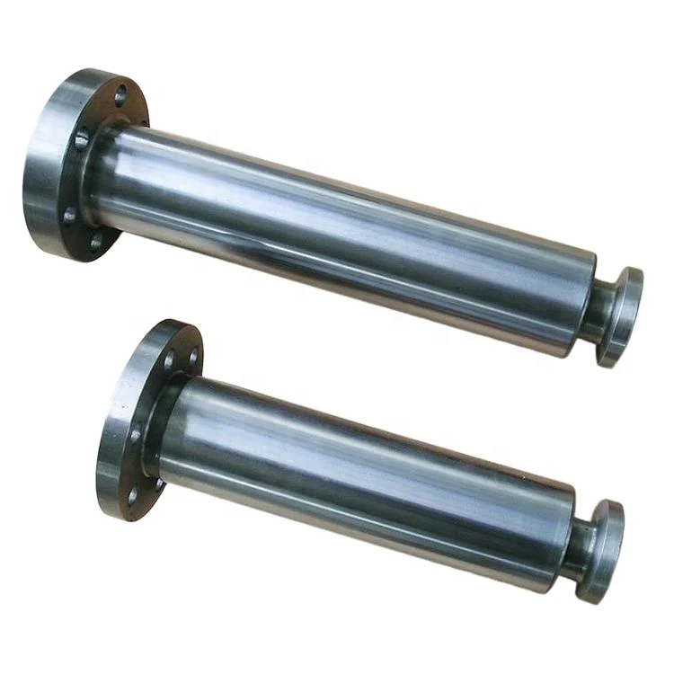
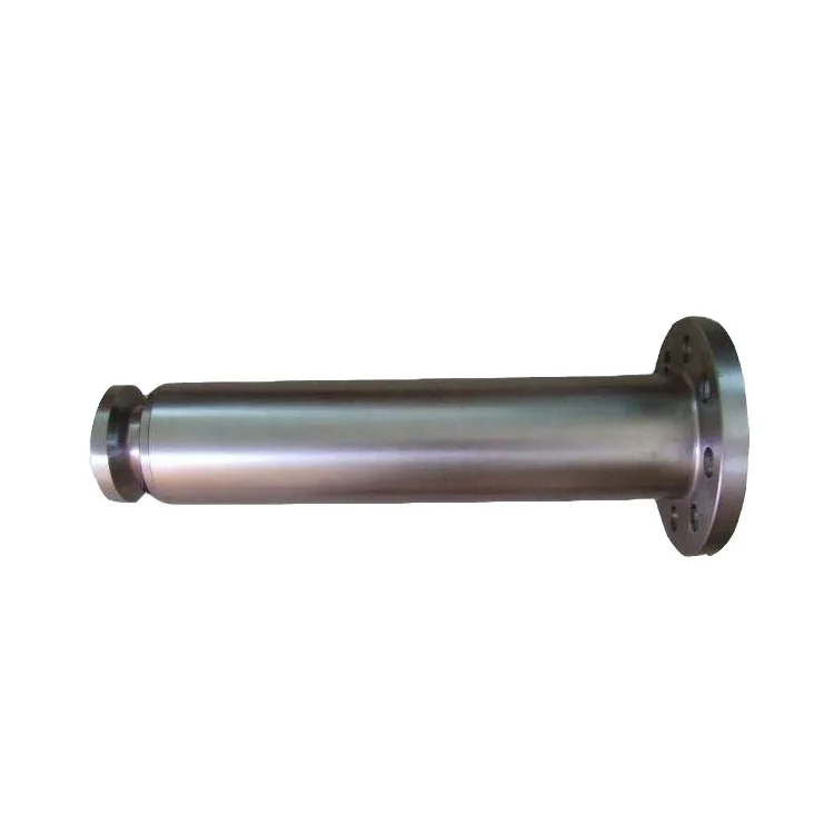
This invention relates in general to pony rods, crossheads, and connecting rods used in plunger type reciprocating pumps and, in particular, to a pony rod, connecting rod, and crosshead assemblies. 2. BACKGROUND OF THE INVENTION
Hydraulic fracturing (also known as well stimulation) is the injection, under pressure, of water, sand, and/or other fluids within a well formation to induce fractures in a rock layer. Oil and Gas drilling operators commonly use hydraulic fracturing, or “fracing” to release petroleum and natural gas as well as other substances from the rock layer. The high pressure injection creates new channels in the rock which can increase the extraction rates and ultimate recovery of fossil fuels. A hydraulic fracturing pump or “frac pump” is used to pump water, sand, gravel, acids, proprietary liquids and concrete into the well formation. The solids pumped down the hole into the fractures keep the fractures from closing after the pressure is released. Operators generally attempt to pump as much volume as possible at or above the pressure necessary to frac the well.
Fracing is very expensive and generally charged by the hour. Because the formation may be located thousands of feet below the earth"s surface, the pressures generated and required by frac pumps are substantial, sometimes exceeding 23,000 pounds per square inch (psi). At peak times, a given frac pump may operate for more than eight consecutive hours (with drive engines running) at as much as 2800 revolutions per minute (rpm).
The frac pump is driven by high horsepower diesel or turbine engines. An engine"s revolutions-per-minute (RPM"s) are usually reduced through the use of a transmission. The transmission is usually multi-geared such that higher pump loads use lower gearing and lighter loads use higher gearing. Internally, a frac pump increases pressure within a fluid cylinder by reciprocating a plunger longitudinally within the fluid head cylinder. A frac pump comprises two major components: a power frame and a fluid head held together by a group of stay rods. Conventional high pressure, high volume frac pumps have either three or five cylinders. A typical power frame consists of a pinion gear, bull gears, crankshaft, rod caps, connecting rods, crossheads and pony rods. Each crosshead and pony rod is maintained in proper position by a respective large brass cylinder pressed into an individual steel support sleeve welded into the power frame. Each crosshead and pony rod is coupled to the respective connecting rod with a separate wrist pin. Each connecting rod is bolted to individual rod caps that are connected to the crankshaft. The crankshaft is connected to either one or two bull gears that are driven in circular motion by a pinion gear.
As mentioned, in most frac pumps, the connecting rod is attached at one end to the crankshaft, and at the other, the crosshead. The crosshead, in turn, is coupled to the pony rod which is connected to a plunger. The connecting rod is connected to the crosshead by a wrist pin inserted through a wrist pin hole positioned in both the connecting rod and the crosshead. Thus, the crankshaft"s rotational movement is transferred through the connecting rod into linear movement by virtue of the sliding arrangement of the crosshead within a brass sleeve. This linear movement, in turn, moves the crosshead and pony rod, which in turn moves the plunger in, on pressure stroke and out on suction stroke, in a linear fashion. Because of the extreme conditions under which a frac pump operates, some of which are discussed above, there is considerable wear and tear on the various component parts. Such wear and tear requires constant maintenance, and ultimately, replacement of worn parts. Maintenance and repair creates machine downtime and increases the overall cost of oil and gas production.
Four of the parts that are susceptible to failure and, thus, machine downtime, are the connecting rod, crosshead, pony rod, and the brass sleeve. As a result of its connection with the crankshaft, the connecting rod transfers the radial energy of the crankshaft into linear motion. The connecting rod may become weakened by the off-center stress produced by the crankshaft rotation. A conventional connecting rod comprises a thicker wall that is required due to its overall straight shank design. Such design and configuration of the conventional connecting rod results in increased weight. Weight is a significant factor for frac pump operators as only so much weight is permitted to be carried down the highway. In operation, an increased weight of moving machine components results in increased horsepower demands. This raises the cost of operation.
The conventional connecting rod has a male knuckle end that, on the compression stroke, pushes against a brass bearing located inside a crosshead female knuckle, and on the suction stroke, pulls against the wrist pin. Due to the loss of oil pressure or poor lubrication of this male/female knuckle arrangement, the connecting rod male knuckle is caused to become worn and/or galled by the brass bearing. Such wear to the male knuckle results in failure and need of replacement of the connecting rod. The connecting rod is very expensive and a difficult part to manufacture due to the configuration of the knuckle end and the way it must be machined. The knuckle end must be ground to the proper size and to a very fine finish so as to move properly against the brass bearing. Because the conventional connecting rod knuckle does not comprise a full circle, proper machining of the knuckle is very time consuming and costly as specialized training and equipment is required.
The conventional crosshead is a casting made of cast iron or steel and is a part that is subject to wear. Virtually all castings are subject to fracturing. The crosshead is pushed and pulled within the brass sleeve which maintains the crosshead in linear alignment. The outside diameter of the crosshead and the brass sleeve within which it travels are each subject to significant wear. The crosshead is in direct contact with the brass sleeve. When the crosshead wears and gets a certain amount of play (loss of fit) the crosshead starts knocking. This, in turn, aggravates wear in the brass cylinder. This wear causes a movement in the connected pony rod which also causes movement in the plunger which, in turn, causes premature loss of the pony rod seal and the pressure seal to the plunger. If the fit of the crosshead is the cause of the play, the crosshead must be replaced. If the brass sleeve is found to be worn, it must be replaced.
Crossheads and brass sleeves are very costly and time consuming to replace. To replace the crossheads or brass sleeves, the pump must be removed from the trailer and entirely disassembled.
As may be seen from the foregoing, in order to replace the brass sleeves, the pump has to be completely disassembled and handled several times on and off different machines. This is a very time consuming, costly and resource intensive operation. To prevent pumping operations from becoming interrupted for prolonged periods of time as a result of brass sleeve replacement, pump owners must purchase more pumps than would otherwise be necessary.
Just as the crosshead and brass sleeves are subject to wear and require replacement, the pony rod is also a part that may require replacement due to wear. The pony rod is clamped to the plunger located in the fluid head. The pony rod is used to transfer the linear motion of the crosshead to the plunger in the fluid head. On the in stroke of the pony rod, the plunger is pulled out causing a suction opening of the intake valve. Such suction opening of the intake valve pulls fracing fluids into the fluid head. On the out stoke of the crosshead, the plunger closes the intake valve and opens an exhaust valve. Such action pushes the fluid in the fluid head out to the wellhead under pressure.
The conventional pony rod is bolted to the crosshead as a separate part. The pony rod transfers energy produced in the crank case to the plunger. Due to its contact with the seal that seals off the pony rod to oil leakage from the power frame and exposure of the pony rod to the outside elements such as dust, acids, fracing fluids, etc., the pony rod is subject to significant wear. The pony rod can also come loose from the crosshead due to the bolts loosening, which can cause catastrophic failure of the frac pump.
In order to extend the life of a pony rod, in the original manufacture, a wear area of the pony rod is undercut, and spray metalized with powdered hard metal. The pony rod is then heat treated so as to bond the metalized surface together. Then the metalized surface is machined in a grinding machine to proper diameter and finish to fit the seals.
After becoming worn, the conventional pony rod can be re-machined. To do so, the old hard surface must be removed by grinding, and re-metalized, heat treated and machined or ground back to proper size. These worn pony rods are usually exchanged for either a rebuilt pony rod or a new one. The metalizing operation of both new and used pony rods requires a large amount of labor, time, and resources. The pump must be disassembled to replace the pony rod. Moreover, a stock pony rod deteriorates each time it is subjected to high temperature by both spraying of metal and heat treatment of the sprayed on surface to make the sprayed metal bond to itself. Each time steel is heated to high temperatures there is a loss of material through oxidation (scale), warping of the metal and softening of the steel. The high heat elongates the grain of the material. Longer grain generally equates to softer steel while smaller grain generally equates to harder steel. The pony rod steel may become soft enough so as to be unable to carry sufficient loads. Also soft steel may result in damage to the clamp end of the pony rod, which calls for complete replacement of the unit. Reworked pony rods have a much higher failure rate. The buyer buys a reworked pony rod to save money but never knows how many times it has been reworked. The buyer may be unaware that a reworked pony rod life is not as long as a new one. In the event of premature failure of a reworked pony rod, the frac pump must again be torn down for replacement. Though conventional pony rods are discarded when a new pump is bought, the pony rods of the present invention may be reused in new pumps. The higher the pressure at which a frac pump runs, the shorter the life of the power frame. Conversely, lower operating pressures extend the life of the power frame. The power frames are heavily stressed during operation. The average power frame is rebuilt up to four times. Power frames running 15,000 lbs. pressure or more last two to three rebuilds. Normal life is between 800 to 1000 hours between rebuilds. The frac pump requires constant monitoring during operation for a multitude of failures that can happen while in operation.
Due to the long rebuild turnaround, operation under less than ideal conditions, and high maintenance costs, frac pump owners inevitably must “over buy” frac pumps to compensate for the number of pumps being out of service. The power frame is the most expensive part of the frac pump. When a power frame is retired, it is sold as junk. An owner replaces the old with a complete new power frame. No old parts are used in the new power frame.
The present invention provides tremendous savings to the user in both rebuild cost and an increase in turnaround time which lowers the quantity of inventory of frac pumps needed to be kept on hand because of rebuilding delays. These delays result from turnaround times that can be as high as six months due to waiting for parts or finding machine time to machine the rebuilds on.
A replaceable pony rod sleeve is provided that can be replaced in the field without disassembling or “tearing down” the machine. The replacement of the pony rod sleeve is fast and inexpensive compared to the normal replacement method which requires the pump to be taken out of service and completely disassembled. The pony rod sleeve contributes to keeping the pump in the field, thus, lowering operation cost not only because of decreased cost involved with replacement but by reducing the need for more inventory to compensate for rebuilding delays.
By providing a pony rod as an integral part of the crosshead significant weight is saved and the pony rod cannot come loose as in the conventional crosshead and bolted on pony rod. In the event the pony rod should come loose, a complete loss of the frac pump could occur resulting in the need to replace the entire pump or at least repair major damage.
The main body of the combination crosshead and pony rod may be reused through several generations of new power frames because everything that can wear out can be replaced. There is no further heat treatment of the body combination crosshead and pony rod, other than the original heat treatment, which greatly increases life of the unit. This invention brings a value not previously seen or offered. There is a much lower cost of operation, reusable parts in the next new machine purchase and much faster turnaround times which also has the benefit of the need for fewer pumps in inventory.
The connecting rod provided in this disclosure attaches to the crankshaft in a similar manner as a conventional connecting rod. However, the modified connecting rod of an embodiment of the present invention comprises a tapered shank instead of a straight shank of the conventional design. As the crankshaft rotates the connecting rod is placed under great stress by the off center push of the crankshaft. The tapered shank of the connecting rod is much stronger than the straight design of the stock connecting rod and puts the wall of the connecting rod more in line with the stress of the pressure stroke. The tapered body also allows a thinner wall, because of its design advantage, and is less likely to break or deflect than the straight design with a good strength advantage. The tapered body has a weight advantage. The bearing end of the connecting rod is a thick walled cylindrical cylinder laying perpendicular to the length wise center of the cross head. It is commonly called a knuckle end. This design is used because it offers more square inches of surface area to handle the tremendous pressures involved in the pressure stroke of the frac pump. The knuckle end pushes a brass or plated steel bearing located inside the crosshead. Lubrication travels through an access hole in the top side of the crosshead, then through the bearing. The knuckle end has a small hole drilled through the top center intersecting the larger hole bored thru lengthwise of the knuckle end. This hole allows access of lubrication to lubricate the wrist pin hole. Due to poor lubrication, loss of oil pressure, worn bearing or worn knuckle end of the connecting rod, the metal between the two surfaces, bearing and knuckle end, can gall or deform. A loss of this bearing causes deformation of the knuckle end of the connecting rod. When there is damage to the knuckle end the connecting rod is replaced at a great cost. The stock knuckle end is not a full circle but requires a very smooth and accurate surface. If this surface is not formed to precise specifications, the bearing may be damaged very quickly which leads to premature pump failure.
Grinding the knuckle end cannot be performed in a full circle. The semicircle machining requirement of the conventional connecting rod requires a specialized grinder to grind the radius of the stock knuckle end and maintain the accuracy required of the part. This grinding operation is slow and very costly.
In a preferred embodiment of the present invention, the wear surface of the knuckle end part of the connecting rod is replaceable. The replaceable sleeve is easy to machine and install. The replaceable sleeve does not require any special machinery and is easily made in mass quantities. The sleeve is made as a thin walled cylinder either heat treated, hard chrome plated, or with other plating options. The replaceable sleeve is ground around a full circle which does away with special machinery, speeds up production and greatly lowers the cost of the sleeve. The replaceable sleeve is then cut to fit the modified cut knuckle end. The finish of the replaceable sleeve becomes the part that facilitates smooth operation rather than knuckle end itself.
The design of the present connecting rod is stronger than a conventional connecting rod and less susceptible to breakage. As the knuckle end is replaceable, there will be no loss of the rod because of wear, loss of oil pressure, galling, or deformation. The new connecting rod can be used in the next new frac pump because of its design and replaceable end. There is nothing to wear out the connecting rod. All of these attributes have a very good cost advantage require less labor than conventional connecting rods and provide a savings in terms of natural and manmade materials. SUMMARY OF THE INVENTION
The present invention in its various embodiments and aspects of such embodiments provides crosshead, pony rod, and connecting rod assemblies which are lighter, will last longer, require less maintenance, and which, when the need arises may be easily repaired or replaced.
In one embodiment, the pony rod comprises a multi-piece assembly and comprises a pony rod base comprising a shank portion and flange. The flange further comprises coupling openings cooperatively arranged to allow coupling of the pony rod base to a receiving portion of the crosshead which comprises crosshead coupling openings. The pony rod shank comprises an elongated cylindrical material further comprising a threaded opening arranged to receive a pony rod cap comprising a threaded post. The pony rod shank is further adapted to receive a pony rod sleeve. The pony rod sleeve comprises an elongated, hollow, cylindrical material comprising an inside diameter slightly larger than an outside diameter of the pony rod shank. The pony rod base further comprises a flange ring at a junction between the flange and pony rod shank. The flange ring has approximately the same size outside diameter as the pony rod sleeve such that when the sleeve is placed in position around the pony rod shank, the flange ring locates the sleeve and the sleeve and flange ring are flush with one another. In this embodiment, the pony rod sleeve has the same outside diameter as the as that of a conventional prior art pony rod.
In other embodiments, the outside surface of the pony rod sleeve or shank can be treated different ways to enhance wear resistance. For instance, the pony rod sleeve or shank may be heat treated to a high hardness, nitride, or plated to enhance wear such as hard chrome or nickel carbide plating.
The length of the pony rod sleeve is longer than the stroke of the assembly. This assures that the seal will wear only on the pony rod sleeve. When the pony rod sleeve is installed properly, a pony rod cap, when sufficiently torqued, helps hold the pony rod sleeve securely and in proper alignment. In a preferred embodiment, a bolt with an opposite thread is tightened through the center of the pony rod cap to keep the cap from loosening. If the end of the conventional pony rod cap is damaged the entire pony rod is generally discarded. However, if the pony rod cap of the present invention is damaged it may be replaced, without disassembling the pump, at a great cost savings to the user.
The pony rod sleeve can be replaced in the field without a tear down of the machine. The replacement of the pony rod sleeve is fast and very inexpensive compared to the normal replacement method which requires the pump being taken out of service and completely disassembled. The pony rod sleeve contributes to keeping the pump in the field, thus, lowering cost to the owners not only because of decreased cost involved with replacement but by reducing the need for more inventory to compensate for rebuilding delays.
In this embodiment, the rear wear bridges are partially semi-circular pieces of material comprising arched surfaces. These arched surfaces comprise an outside arc slightly larger than an outside arc of the crosshead cylinder and sides. When originally mounted on the crosshead, the rear wear bridges are slightly raised with respect to the crosshead in the areas on the top and bottom of the crosshead. The rear wear bridge sides nest within the crosshead cylinder adjacent to the crosshead extensions. At the end closest to the pony rod shank, the crosshead of this embodiment is further adapted to receive one or more circular or semi-circular front wear bridges.
In another embodiment of the present invention, the unified crosshead and pony rod shank assembly comprises a scalloped crosshead cylinder portion. In this embodiment, an opening between the rear wear bridges and the crosshead cylinder remains on the top and bottom of the crosshead after coupling the crosshead cylinder with the rear wear bridge.
In embodiments comprising a threaded opening arranged to receive the pony rod cap threaded post, the internal thread of the threaded opening and the external thread of the threaded post are left handed. A right hand safety bolt allows each threaded item to work against each other to keep them tightly working against each other. It is easier to machine a left hand thread than to purchase a left handed bolt which keeps costs down.
In other embodiments, the pony rod cap comprises one or more flat sides adapted to receive a conventional tool such as a wrench or socket. Such flat sides permit the pony rod cap to be easily torqued into place or removed.
In another embodiment, the modified crosshead assembly is adapted to receive a modified connecting rod. The connecting rod of this embodiment comprises a connecting plate, an elongated portion, a wrist pin receiver (commonly called a knuckle end), a wrist pin hole, and a wear plate. The connecting plate is adapted to be mounted on the crankshaft. The elongated portion spans between the connecting plate and the wrist pin receiver. The wrist pin receiver is tubular in shape having a rounded exterior configuration and a hollow interior portion comprising the wrist pin hole adapted to receive a wrist pin which secures the connecting rod to the crosshead. The wear plate comprises a “C” shaped configuration with a generally rounded interior surface conforming to the contours of an outside portion of the wrist pin receiver such that the wear plate may be mounted onto the wrist pin receiver and held in place by tacking, staking, gluing, etc. In this embodiment, the connecting rod comprises a tapered hollow cylinder.
In another embodiment, the connecting rod is comprised of a flange end, tapered shank, a knuckle or barreled end having a large bore lengthwise that a brass bushing and wrist pin fit into. At the top dead center of the knuckle end is a smaller opening or hole extending to the wrist pin hole. Through the wall of the steel support and brass sleeve is a pipe threaded through hole. A threaded oil line is positioned within this pipe thread. When the oil pump to the frac pump is operated, an oil stream is caused to enter the brass sleeve that holds the crosshead. The hole is located at the top of the horizontal cylinder near the middle of the brass sleeve. There is a hole drilled through the side if the crosshead that is drilled down to the center of the crosshead just in front of the brass bearing fit on the inside of the crosshead. A hole is drilled through the center of brass bearing fit intersecting the hole drilled through the side of the crosshead. As the crosshead travels back and forth within brass sleeve, the crosshead travels beneath the oil stream. The oil s


 8613371530291