
mud pump pop off valve free sample

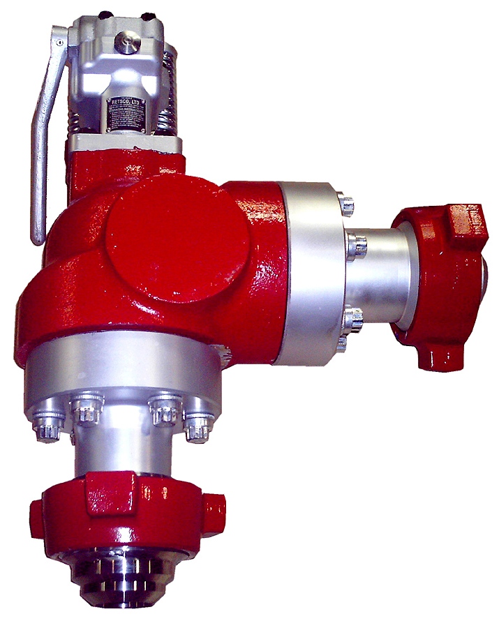
Pressure relief valves are installed on mud pumps in order to prevent an overpressure which could result in a serious damage of the pump and serious or fatal injury to personnel.
The discharge pressure is routed to the closer mud tank, via a 3” XXS line clamped strongly on tank side . Mud is flowing into the mud tank until line bled off, bearing in mind that minimum slope is required to avoid mud settling in pipe ( around 1 inch/meter).
Pressure relief valves are set usually to 90% of the maximum working pressure of the liners in use. Read carefully manufacturer chart for pressure setting versus size of liners.
Discharge pressure losses close to the maximum preset pressure.The Pressure relief valves are usually installed on a upper point of the discharge side of the mud pumps.
The pressure relief valve can be reset, if not damaged during the release of pressure. Special care should be taken if no working platform available to access the PRV.
For 50 years, Giant Pumps has offered the most dependable positive displacement high-pressure triplex pumps available. Designed and built to the highest quality standards, customers count on Giant Pumps products to keep their equipment running. Every design detail of Giant Pumps products is optimized for long-life and reliable performance, making Giant Pumps the most trusted name in high-pressure pumps and systems.
For 50 years, Giant Pumps has offered the most dependable positive displacement high-pressure triplex pumps available. Designed and built to the highest quality standards, customers count on Giant Pumps products to keep their equipment running. Every design detail of Giant Pumps products is optimized for long-life and reliable performance, making Giant Pumps the most trusted name in high-pressure pumps and systems.
Created specifically for drilling equipment inspectors and others in the oil and gas industry, the Oil Rig Mud Pump Inspection app allows you to easily document the status and safety of your oil rigs using just a mobile device. Quickly resolve any damage or needed maintenance with photos and GPS locations and sync to the cloud for easy access. The app is completely customizable to fit your inspection needs and works even without an internet signal.Try Template
If you run a mud rig, you have probably figured out that the mud pump is the heart of the rig. Without it, drilling stops. Keeping your pump in good shape is key to productivity. There are some tricks I have learned over the years to keeping a pump running well.
First, you need a baseline to know how well your pump is doing. When it’s freshly rebuilt, it will be at the top efficiency. An easy way to establish this efficiency is to pump through an orifice at a known rate with a known fluid. When I rig up, I hook my water truck to my pump and pump through my mixing hopper at idle. My hopper has a ½-inch nozzle in it, so at idle I see about 80 psi on the pump when it’s fresh. Since I’m pumping clear water at a known rate, I do this on every job.
As time goes on and I drill more hole, and the pump wears, I start seeing a decrease in my initial pressure — 75, then 70, then 65, etc. This tells me I better order parts. Funny thing is, I don’t usually notice it when drilling. After all, I am running it a lot faster, and it’s hard to tell the difference in a few gallons a minute until it really goes south. This method has saved me quite a bit on parts over the years. When the swabs wear they start to leak. This bypass pushes mud around the swab, against the liners, greatly accelerating wear. By changing the swab at the first sign of bypass, I am able to get at least three sets of swabs before I have to change liners. This saves money.
Before I figured this out, I would sometimes have to run swabs to complete failure. (I was just a hand then, so it wasn’t my rig.) When I tore the pump down to put in swabs, lo-and-behold, the liners were cut so badly that they had to be changed too. That is false economy. Clean mud helps too. A desander will pay for itself in pump parts quicker than you think, and make a better hole to boot. Pump rods and packing last longer if they are washed and lubricated. In the oilfield, we use a petroleum-based lube, but that it not a good idea in the water well business. I generally use water and dish soap. Sometimes it tends to foam too much, so I add a few tablets of an over the counter, anti-gas product, like Di-Gel or Gas-Ex, to cut the foaming.
Maintenance on the gear end of your pump is important, too. Maintenance is WAY cheaper than repair. The first, and most important, thing is clean oil. On a duplex pump, there is a packing gland called an oil-stop on the gear end of the rod. This is often overlooked because the pump pumps just as well with a bad oil-stop. But as soon as the fluid end packing starts leaking, it pumps mud and abrasive sand into the gear end. This is a recipe for disaster. Eventually, all gear ends start knocking. The driller should notice this, and start planning. A lot of times, a driller will change the oil and go to a higher viscosity oil, thinking this will help cushion the knock. Wrong. Most smaller duplex pumps are splash lubricated. Thicker oil does not splash as well, and actually starves the bearings of lubrication and accelerates wear. I use 85W90 in my pumps. A thicker 90W140 weight wears them out a lot quicker. You can improve the “climbing” ability of the oil with an additive, like Lucas, if you want. That seems to help.
Outside the pump, but still an important part of the system, is the pop-off, or pressure relief valve. When you plug the bit, or your brother-in-law closes the discharge valve on a running pump, something has to give. Without a good, tested pop-off, the part that fails will be hard to fix, expensive and probably hurt somebody. Pop-off valve are easily overlooked. If you pump cement through your rig pump, it should be a standard part of the cleanup procedure. Remove the shear pin and wash through the valve. In the old days, these valves were made to use a common nail as the shear pin, but now nails come in so many grades that they are no longer a reliable tool. Rated shear pins are available for this. In no case should you ever run an Allen wrench! They are hardened steel and will hurt somebody or destroy your pump.
One last thing that helps pump maintenance is a good pulsation dampener. It should be close to the pump discharge, properly sized and drained after every job. Bet you never thought of that one. If your pump discharge goes straight to the standpipe, when you finish the job your standpipe is still full of fluid. Eventually the pulsation dampener will water-log and become useless. This is hard on the gear end of the pump. Open a valve that drains it at the end of every job. It’ll make your pump run smoother and longer.

Method and device for preventing a primary relief valve (12) in a mud system (1) from opening at a pressure lower than a nominal opening pressure, and where the mud system (1) includes a mud pump (2), wherein the method includes: - installing an flow restrictor (16) between the mud pump (2) and the primary relief valve (12); and -providing a cavity (20) between the flow restrictor (16) and the primary relief valve (12).
There is provided a method for preventing a primary mud re¬ lief valve from incorrect opening. More precisely there is provided method for preventing a primary relief valve in a mud system from incorrect opening, where the mud system includes a mud pump.
Mud systems, as known from drilling rigs, normally include a mud pump, a pulsation dampener and a relief valve, the latter herein termed "primary relief valve". The main pump is typi¬ cally a triplex pump. This kind of pump delivers a flow rate which is far from constant but fluctuates much because of i) variable piston speed - the pump is crank shaft driven, ii) mud compressibility and iii) valve and fluid inertia. The pulsation dampener is therefore included to smoothen the flow rate and mitigate the resulting pressure fluctuations. The primary relief valve may be of a design known as a "pop-off valve" in the industry, or a rupture disk. Other types of re¬ lief valves are also known.
The primary relief valve is a safety valve that is designed to prevent excessive pressure and possible hazards in the case the pump pressure exceed the certified pressure limit for the system. Normally the so-called trip pressure, at
which the primary relief valve shall switch from a closed to an open state, is set slightly higher that the system pres¬ sure of typically 5000 psi (345 bar) .
It is a well-known problem in the industry that the primary relief valve sometimes trips frequently even though the rec¬ orded pressure levels never reached the nominal trip pressure level .
Tripping of a primary relief valve represents a costly and highly undesired disruption of the drilling process, both because of the time it takes to refit a new rupture disk or to reset a resettable primary relief valve and because the well can be damaged during long periods of no circulation. To lower the risk for primary relief valve tripping one can therefore reduce maximum working pressure to say 80 per cent of the system pressure limit. This is also a costly solution be¬ cause flow rate and pressure is often a limiting factor that can lead to slower drilling and even cause well stability problems. The opposite solution of increasing the nominal trip pressure to compensate for the dynamic effect is also a highly undesirable solution that may lead to damage in other parts of the mud system. It may even be illegal to raise the nominal relief valve pressure to more than a few per cent over the certified system pressure.
According to a first aspect of the invention there is provid¬ ed a method for preventing a primary relief valve in a mud system from opening at a pressure lower than a nominal open-
A field study of above stated problem has revealed that the reason for the tripping of the primary relief valve at a pressure lower than the nominal opening pressure, most likely is relatively large pressure fluctuations in a pop-off line. Despite of the damping action of a pulsation dampener, there are substantial residual pressure fluctuation present in a discharge pipe between the pump and the dampener. The pop-off line itself represents a hydraulic resonator that can signif¬ icantly amplify these residual fluctuations at frequencies close to resonance frequencies. This explanation is supported by special pressure measurements just below the primary re¬ lief valve showing that the peak dynamic pressure can some¬ times exceed 115 per cent of the mean pressure.
These pressure fluctuations can lead to undesired primary re¬ lief valve trips, both because the peak pressure are really higher than seen on the standard pressure sensors, and be¬ cause they can lead to fatigue and lowering of the real trip pressure. This fatigue effect is especially relevant if the primary relief valve is a rupture disk.
It has thus been found that the opening of the primary relief valve is related to pressure variation at higher frequencies, typically in the region of 40Hz. Pressure fluctuations at this frequency has been measured to be up to 40 bars. Such fluctuations are superimposed on the mean pressure and are believed to cause the tripping of the primary relief valve at a pressure lower than the nominal opening pressure.
The high frequency pressure fluctuation components appear to be generated by the mud pumps and are related to the pump valve action. Both mud compressibility and pump valve inertia tend to cause sudden changes in the pump flow rate when the pump discharge valves open and closes. The changes give rise to a pressure pulse that is enhanced at frequencies close to the resonance frequencies of the closed primary relief valve line .
By installing a flow restriction between the mud pump and the primary relief valve in combination with a cavity positioned between the flow restriction and the primary relief valve, these higher frequency pressure fluctuations are dampened. The pressure acting on the primary relief valve is then the mean operating pressure of the mud system. The relation between the size of the flow restrictor and the cavity volume should be calculated according to known principles, or it should be found experimentally by testing different
The method may include placing a second relief valve in par¬ allel with the flow restrictor, preferably with a lower nominal trip pressure than the primary relief valve.
This second relief valve will normally only experience the dynamic pressure difference as it receives the mud pump pres¬ sure on one side and the smoothed pressure at the cavity on the other side.
According to a second aspect of the invention there is pro¬ vided device for preventing a primary relief valve in a mud system from opening at a pressure lower than a nominal opening pressure and where the mud system includes a mud pump, wherein a flow restrictor is positioned between the mud pump and the primary relief valve, and where a cavity is provided between the flow restrictor and the primary relief valve.
In a practical embodiment of the invention, the primary re¬ lief valve, the flow restriction, the second relief valve and the cavity may be produced as one unit that is fairly compact and suitable for installation in a mud system.
The method and device according to the invention render it possible to overcome the long felt problem of incorrect open¬ ing of the primary relief valve of a mud system.
On the drawings the reference number 1 denotes a part of a mud system that includes a mud pump 2 that draws mud from a mud reservoir 4 and discharge the mud via a discharge pipe 6 into a so-called stand pipe 8. A pulsation dampener 10 is connected to the discharge pipe 6. A primary relief valve 12 is connected to the discharge pipe 6 via a so-called pop-off line 14. In this exemplary embodiment, the primary relief valve 12 is a pop-off valve. However, in other embodiments, the primary relief valve 12 may be a rupture disk or another suitable valve.
According to the present invention a flow restriction 16 is provided between the mud pump 2 and the primary relief valve 12, or more precisely between the discharge pipe 6 and the primary relief valve 12.
A second relief valve 18, which may be of a type similar to the primary relief valve 12, is positioned in parallel with the flow restriction 16. A cavity 20 is closed off in the pop-off line 14 between the primary relief valve 12 and the second relief valve 18. The cavity 20 communicates with the discharge pipe 6 through the flow restriction 16.
This done, as the mud pump 2 operates, the high frequency pressure fluctuation components are dampened in the flow re¬ striction 16/cavity 20 dampener system. Thus, the primary relief valve 12 only experiences the average pressure present in the cavity 20.
The second relief valve 18 has the pressure from the mud pump 2 acting on the side facing the discharge pipe 6, while the average pressure is acting on the side of the second relief valve 18 facing the cavity 20. The resultant pressure across the second relief valve 18 equals the dynamic pressure fluc¬ tuations in the discharge line 6, normally with zero mean.
Then, as the flow through the flow restriction 16 is minute compared to that of the primary relief valve 12, the pressure over the second relief valve 18 will equal the full pressure from the mud pump 2. The second relief valve 18 will then al¬ so open if the high average pressure is still present. To en¬ sure tripping of the second relief valve 18, its trip pres¬ sure may preferably be slightly lower than the trip pressure of the primary relief valve 12.
In an alternative embodiment, see fig. 2, the pressure sens¬ ing component of the second relief valve 18 is a rupture disk 22. A flow restriction 16 is incorporated in the rupture disk
22, see fig. 3. Aside from the second relief valve 18 being a rupture disk in this embodiment, rather than a pop-off valve, mud system 1 and its functioning are as previously described.
1. Method for preventing a primary relief valve (12) in a mud system (1) from opening at a pressure substantially lower that a nominal opening pressure, where the mud sys¬ tem (1) includes a mud pump (2) , c h a r a c t e r i z e d i n that the method includes:
5. A device for preventing a primary relief valve (12) in a mud system (1) from opening at a pressure lower than a nominal opening pressure and where the mud system (1) in¬ cludes a mud pump (2), c h a r a c t e r i z e d b y that a flow restrictor (16) is positioned between the mud pump (2) and the primary relief valve (12), and that a cavity (20) is provided between the flow restrictor (16) and the primary relief valve (12) . Device according to claim 5, c h a r a c t e r i z e d i n that a second relief valve (18) is placed in paral¬ lel with the flow resistor (16) .

As an integral part of onshore and offshore drilling, mud pumps circulate drilling fluids to facilitate drilling oil and natural gas wells. Mud pumps stabilize pressure and support the well during the drilling process and drilling fluids provide friction reduction and a means to remove cuttings. A leak detection system for hex pumps was created for a hex mud pump with six pistons, six suction valves, and six discharge valves. The six pistons are driven by a rotating, asymmetric cam. The system monitors the suction and discharge valves using accelerometers.
Valve leaks in piston pumps are often discovered at a late stage when the leaks are so severe that they induce large discharge pressure fluctuations and create washout damage (Figure 1). When a severe leak is detected, it is localized manually by listening to the fluid modules while the pump is running but it is difficult to uniquely localize the leak and distinguish between a suction valve leak and a discharge valve leak.
Human exposure to hazards is the main disadvantage of manual detection, verification, and localization. Mud pumps convert large amounts of power and often output high pressures up to 350 Bar discharge. Additional equipment in pump rooms also generates high acoustic noise pressure levels that can exceed 100 dBA and cause health and hearing damage if humans are not correctly protected.
Valve leaks often develop quickly, so manual detection gives very little time to prepare for exchanging the defective valve(s) after the leak is detected. If the leak source is uncertain, searching for the defective valve(s) can be costly and time-consuming.
During a vibration monitoring project for hex pumps, a Norwegian oil well company discovered the possibility of detecting leaks using accelerometers. Vibrations were recorded at different locations, both on the pump and on the discharge line, along with suction pressure, discharge pressure, and pump speeds for different pump conditions. A 20-kHz sampling frequency was used and 5-second snapshots were taken with intervals of a few minutes. On one occasion, the vibration signature significantly changed during a 15-minute period; the spot was a growing valve leak.
Based on that encouraging experience, the company wanted to include this condition-based maintenance system as a standard feature on all hex pumps, so it developed the system as a standalone module to add to the existing hex pump control system. Slightly simplified, it consists of the following components: accelerometers (one per valve block), a proximity sensor picking up pump speed and phase, a discharge pressure sensor, an embedded monitoring system (an NI CompactRIO system with acquisition modules for powering the accelerometers and acquiring high-frequency data), signal processing software and alarm logics implemented using NI LabVIEW software running on the CompactRIO monitoring system, and an HMI user interface developed in LabVIEW.
The data acquisition and signal processing are briefly described by the following steps: Capture high-rate data (25-kHz sample rate) from all sensors during a short time interval covering at least one pump cycle.
Construct adjusted window functions that selectively pick the filtered acceleration signal in every valve closing phase (adjusted here means narrowed and time lag corrected so that valve closing spikes are excluded).
The default sampling frequency of the signals is 25 kHz but the system can handle higher rates if necessary. The bandpass filter is optional but experience shows that it improves contrast and detection sensitivity. Signal strength normalization by the median vibration level makes the detection nearly independent of the inherent ambient vibrations, which increase rapidly with increasing pump speed and discharge pressure. The last requirement — that the detected leaks last for a set time — eliminates erratic alarms caused by debris or large particles that can cause temporary seal malfunction.
A desktop application can be used on a terminal to review the LDS and read raw logs and trend files directly from the LDS. This additional feature gives the operator the chance to get a closer view of the vibrations and perform audio playback to the user. Also, the high-rate log of the discharge pressure can be viewed to reveal a cyclic variation drop. This helps provide a better understanding of what is happening with the valves.
Figure 2 shows a diagnosis screen from the hex pump control screen delivered by the leak detection system. It shows a very clear overview of the valve status and a vibration level trend of all valves.
Based on the field experience of the new leak detection system, it was concluded that the leak detection method offers many advantages over current practices, including the following: High sensitivity for early leak detection and localization
The NI tools for prototyping the system provided an embedded deployment system that can reliably retrofit to existing pumps. In comparison to other leak detection methods based on analyzing discharge pressure, the vibration-based methods are more robust and reliable, especially when it comes to localizing a leak. Studies showed that an alternative method can be applied for shaft-driven piston pumps having either an integrated valve block or split blocks with a high vibration transfer. Leak localization for this kind of pump is mainly based on the phase of the pulsating vibration level. It can be used to localize one dominating leaky valve at a time.

Made from 6061 Billet Aluminum stock, it is a two piece adjustable valve that relieves pressure in the crankcase due to blown head gaskets or piston failure which can result in lots of air volume bypassed to the engines crankcase. It also protects in the situation where the vacuum pump isn"t working due to a thrown belt. The GZ Blow Off Valve PN VCB100B consists of a base with a nylon washer and nut that can be installed in a standard grommet hole in a valve cover or placed in a valley pan and a top that may be removed to replace the spring of Teflon ball inside. The top has an o-ring between it and the base to which is attached for leak free sealing. Once the valve is activated, the blow-by gases are vented through a fitting in the top which may be routed to a catch can or other means of containing fluids in the gases.
A pressure relief valve (blow off valve) is essential for any turbo, blower or nitrous equipped high performance engine with a Vacuum Pump. If for some reason the pump can"t keep up with crankcase pressure (like a hole in the piston on a blower car), the blow off valve will safely vent that pressure to a puke tank instead of pushing out a gasket in the engine and getting oil under the tires.
The disclosure relates generally to devices and methods for preventing a primary mud relief valve from incorrect opening. More particularly, the disclosure relates to devices and methods for preventing a primary relief valve in a mud system from incorrect opening.
Mud systems, as known from drilling rigs, normally include a mud pump, a pulsation dampener and a relief valve, the latter herein termed “primary relief valve”. The main pump is typically a triplex pump. This kind of pump delivers a flow rate which is far from constant and fluctuates much because of i) variable piston speed—the pump is crank shaft driven, ii) mud compressibility and iii) valve and fluid inertia. The pulsation dampener is therefore included to smoothen the flow rate and mitigate the resulting pressure fluctuations. The primary relief valve may be of a design known as a “pop-off valve” in the industry, or a rupture disk. Other types of relief valves are also known.
The primary relief valve is a safety valve that is designed to prevent excessive pressure and possible hazards in the case the pump pressure exceeds the certified pressure limit for the system. Normally the so-called trip pressure, at which the primary relief valve shall switch from a closed to an open state, is set slightly higher that the system pressure of typically 5000 psi (345 bar).
It is a well-known problem in the industry that the primary relief valve sometimes trips frequently even though the recorded pressure levels never reached the nominal trip pressure level.
Tripping of a primary relief valve represents a costly and highly undesired disruption of the drilling process, both because of the time it takes to refit a new rupture disk or to reset a resettable primary relief valve and because the well can be damaged during long periods of no circulation. To lower the risk for primary relief valve tripping one can therefore reduce maximum working pressure to say 80 per cent of the system pressure limit. This is also a costly solution because flow rate and pressure is often a limiting factor that can lead to slower drilling and even cause well stability problems. The opposite solution of increasing the nominal trip pressure to compensate for the dynamic effect is also a highly undesirable solution that may lead to damage in other parts of the mud system. It may even be illegal to raise the nominal relief valve pressure to more than a few per cent over the certified system pressure.
According to a first aspect of the invention there is provided a method for preventing a primary relief valve in a mud system from opening at a pressure lower than a nominal opening pressure, and where the mud system includes a mud pump, wherein the method includes: installing a flow restrictor between the mud pump and the primary relief valve; and
A field study of above stated problem has revealed that the reason for the tripping of the primary relief valve at a pressure lower than the nominal opening pressure, most likely is relatively large pressure fluctuations in a pop-off line. Despite of the damping action of a pulsation dampener, there are substantial residual pressure fluctuation present in a discharge pipe between the pump and the dampener. The pop-off line itself represents a hydraulic resonator that can significantly amplify these residual fluctuations at frequencies close to resonance frequencies. This explanation is supported by special pressure measurements just below the primary relief valve showing that the peak dynamic pressure can sometimes exceed 115 per cent of the mean pressure.
These pressure fluctuations can lead to undesired primary relief valve trips, both because the peak pressure are really higher than seen on the standard pressure sensors, and because they can lead to fatigue and lowering of the real trip pressure. This fatigue effect is especially relevant if the primary relief valve is a rupture disk.
It has thus been found that the opening of the primary relief valve is related to pressure variation at higher frequencies, typically in the region of 40 Hz. Pressure fluctuations at this frequency has been measured to be up to 40 bars. Such fluctuations are superimposed on the mean pressure and are believed to cause the tripping of the primary relief valve at a pressure lower than the nominal opening pressure.
The high frequency pressure fluctuation components appear to be generated by the mud pumps and are related to the pump valve action. Both mud compressibility and pump valve inertia tend to cause sudden changes in the pump flow rate when the pump discharge valves open and closes. The changes give rise to a pressure pulse that is enhanced at frequencies close to the resonance frequencies of the closed primary relief valve line.
By installing a flow restriction between the mud pump and the primary relief valve in combination with a cavity positioned between the flow restriction and the primary relief valve, these higher frequency pressure fluctuations are dampened. The pressure acting on the primary relief valve is then the mean operating pressure of the mud system. The relation between the size of the flow restrictor and the cavity volume should be calculated according to known principles, or it should be found experimentally by testing different size/volume ratios.
The method may include placing a second relief valve in parallel with the flow restrictor, preferably with a lower nominal trip pressure than the primary relief valve. This second relief valve will normally only experience the dynamic pressure difference as it receives the mud pump pressure on one side and the smoothed pressure at the cavity on the other side.
According to a second aspect of the invention there is provided device for preventing a primary relief valve in a mud system from opening at a pressure lower than a nominal opening pressure and where the mud system includes a mud pump, wherein a flow restrictor is positioned between the mud pump and the primary relief valve, and where a cavity is provided between the flow restrictor and the primary relief valve.
In a practical embodiment of the invention, the primary relief valve, the flow restriction, the second relief valve and the cavity may be produced as one unit that is fairly compact and suitable for installation in a mud system.
The method and device according to the invention render it possible to overcome the long felt problem of incorrect opening of the primary relief valve of a mud system.
FIG. 2 is a cross-sectional view of an embodiment in accordance with the principles described herein where the flow restriction is placed in the second relief valve; and
On the drawings the reference number 1 denotes a part of a mud system that includes a mud pump 2 that draws mud from a mud reservoir 4 and discharge the mud via a discharge pipe 6 into a so-called stand pipe 8. A pulsation dampener 10 is connected to the discharge pipe 6. A primary relief valve 12 is connected to the discharge pipe 6 via a so-called pop-off line 14. In this exemplary embodiment, the primary relief valve 12 is a pop-off valve. However, in other embodiments, the primary relief valve 12 may be a rupture disk or another suitable valve.
In this embodiment, a flow restriction 16 is provided between the mud pump 2 and the primary relief valve 12, or more precisely between the discharge pipe 6 and the primary relief valve 12.
A second relief valve 18, which may be of a type similar to the primary relief valve 12, is positioned in parallel with the flow restriction 16. A cavity 20 is closed off in the pop-off line 14 between the primary relief valve 12 and the second relief valve 18. The cavity 20 communicates with the discharge pipe 6 through the flow restriction 16.
This done, as the mud pump 2 operates, the high frequency pressure fluctuation components are dampened in the flow restriction 16/cavity 20 dampener system. Thus, the primary relief valve 12 only experiences the average pressure present in the cavity 20.
The second relief valve 18 has the pressure from the mud pump 2 acting on the side facing the discharge pipe 6, while the average pressure is acting on the side of the second relief valve 18 facing the cavity 20. The resultant pressure across the second relief valve 18 equals the dynamic pressure fluctuations in the discharge line 6, normally with zero mean.
If the average pressure exceeds the trip pressure of the primary relief valve 12, the primary relief valve 12 opens. Then, as the flow through the flow restriction 16 is minute compared to that of the primary relief valve 12, the pressure over the second relief valve 18 will equal the full pressure from the mud pump 2. The second relief valve 18 will then also open if the high average pressure is still present. To ensure tripping of the second relief valve 18, its trip pressure may preferably be slightly lower than the trip pressure of the primary relief valve 12.
In an alternative embodiment shown in FIG. 2, the pressure sensing component of the second relief valve 18 is a rupture disk 22. A flow restriction 16 is incorporated in the rupture disk 22, see FIG. 3. Aside from the second relief valve 18 being a rupture disk in this embodiment, rather than a pop-off valve, mud system 1 and its functioning are as previously described.

A ball valve is a shut-off valve that directs the flow of a fluid by means of a rotary ball having a hole. There are a few potential ball valve failures like getting stuck, fluid leakage, corrosion, and overheating, due to which the valve may not function properly. It is possible to troubleshoot these issues rather than replacing the valve entirely in most cases. This article discusses the common issues a ball valve faces and how to troubleshoot them.
A ball valve is a shut-off valve that allows or prevents fluid flow (liquid or gas) through an installation. Ball valves are the most common and reliable valve type used to regulate water flow. The valve consists of a rotating sphere containing a hole. The sphere is attached to a lever handle that can be turned to operate the valve. Read our article on ball valves for more details on the working mechanism and parts of a ball valve.
While PVC ball valves are the most popular type, ball valves are also available in stainless steel, brass, and other materials. Read our article on ball valve selection for more details on choosing a ball valve for a particular application. Every ball valve shows symptoms of wearing down over time when used continuously. Also, the valve may leak if it is used after a certain period of inactivity. This requires halting the current operation and removing the ball valve from the system to get the pieces working again. To avoid these problems and system shutdowns, the best solution is to figure out the average life expectancy of the ball valve. It is possible to know roughly when to swap them out without getting caught off-guard. The average life expectancy of a ball valve is approximately eight to ten years.
Ball valves go through extensive wear and tear due to the constant rotation it encounters to close and open the valve. Sometimes ball valves stop working properly due to corrosion of the various valve parts. It is important to understand different potential ball valve failure methods to properly troubleshoot applications.
Gate valves, ball valves, and butterfly valves are commonly used in households to start, stop, or channel water supply to multiple locations. These valves can be controlled electrically through an actuator or manually through knobs or levers. It is necessary to identify the type of valve being checked on. A gate valve has a knob that looks like a circular spigot, whereas a ball valve has a handle like a lever. Manually operated butterfly valves can have a crank, handwheel, or lever to operate the valve.
To turn the water supply off in the case of a gate valve or butterfly valve, rotate the handle by a few turns clockwise until it can"t be turned any further. To stop the fluid flow through a ball valve, turn the lever 90 degrees clockwise.
Two-piece ball valve: A two-piece ball valve consists of two individual pieces. The first piece has an end connection and the body, and the second piece fits into this piece. Once installed, these valves have to be removed from service for repair works.
Three-piece ball valve: A three-piece ball valve consists of three pieces: a body and two end caps. Both end caps are welded or threaded into the pipe. The main body section can be easily uninstalled for cleaning or repair without removing the end caps, thereby preventing a total line shutdown during maintenance works.
Read our article on 1, 2, and 3-piece ball valves for more details. The main issues and troubleshooting mechanisms of ball valves are discussed in the next sections.
Ball valves that are not exercised continuously may leak a small amount of water when turned off. When the ball valve is shut off, water may find a way out, especially if there is an issue with the valve sealing. In some cases replacing the valve may not be an easy solution, especially if the old valve is fitted in a tight spot. Tighten up the valve fittings with a pair of pliers and check if it stops the leak. If not, replace the seal inside the valve or just get a new valve altogether.
Sometimes a ball valve cannot be turned all the way to shut it off completely. If the valve closes only partially, in most cases, it may be needed to replace the valve seat or replace it with a new valve that works more steadily.
All valve seats are not designed to be removed. Inspect inside the valve body, and if it has a hexagonal or square bore or a screwdriver slot, the seat can be replaced.
Treating a partially open ball valve is crucial since a shut-off valve that doesn’t close completely can not do its job in an extreme situation, leading to leakage of poisonous gas or leaving an apartment filled with water.
Ball valves are commonly used valves for main water and various branch shutoffs. This valve functions as an ON/OFF valve which means that the valve should be either completely open allowing full flow, or completely closed, stopping the entire water flow. Occasionally, it may be necessary to loosen a PVC ball valve because it is stuck or tight, thereby creating an obstruction to fluid flow. If a ball valve won’t open, perform the following steps to rectify the issue:
Gently hammer the valve body multiple times on the valve body to break and free up the particles that are trapped between the ball and the valve body. Make sure not to pound a PVC valve too hard as it can easily crack.
Gently wiggle and rock the valve handle to help service the ball element and force it to move. Also, try to remove the valve handle and turn the valve a few times using a plier to help it move freely, and place the handle back on the valve using its screw. If these steps don’t work, move on to step 2.
Note: WD-40 is a lubricant that can reach and lubricate even the most difficult joints of a shutoff valve by removing the rust and corrosive metals. It is fine to use WD-40 on a water shut-off valve. The solution is non-lethal; hence, it won’t damage the threads and pipe. WD-40 contains petroleum-based oils; hence always read the precautions on the valve body before using the lubricant on plastic-based valves as it can melt the plastic upon application.
Spray a lubricant like WD-40 on the valve where the handle enters the valve body. Let it sit for around 20 minutes. However, it is not a good idea to use WD-40 on plastic as plastics are generally not affected by this lubricant. Hence, WD-40 doesn’t work on PVC valves.
Then, position a pipe wrench around the handle and try to turn the valve. If it moves, open and close the valve multiple times to loosen it. Then move to step 3.
If the valve doesn’t move even after performing Steps 1-3, it is time to replace the ball valve. Read our article on ball valve leakage troubleshooting for more information on how to replace a ball valve.
The buildup of sediment and dirt within the ball valve can make it difficult to open and close. Take the valve apart and clean out any visible dirt if this happens.
The fluid continuously pushes against the ball valve, due to which the valve’s O-ring gets worn down over time. This is a natural symptom of valve usage; therefore, get a new O-ring when it shows symptoms of wearing down. Turning down the liquid intensity flowing through the valve can help extend the life span of these O-rings. Read our article on preventing O-ring damage for more details.
The inner packing of the valve stem can get worn out over time. Replace the valve stem in case of any scratching or damage before the whole unit falls apart.
In electric ball valves, an actuator controls the flow of gas/liquid through the valve. For electric actuators, make sure that the voltage applied to the actuator is not too high to prevent the risk of valve overheating. Read our article on electric ball valves for more details on the actuator selection and operating principles.
It is important to check the shut-off valves occasionally for possible faults. Finding out one isn’t working in a non-emergency situation is much less stressful and allows ample time to get it fixed. Finding out it doesn’t work when the valve is needed the most will pose a bigger problem out of something that could have been little more than just an inconvenience.

RM2CD8621–Crude oil stack valve, blowout preventer, gas flare, flare stack, pressure relief valve, stack valve, crude oil, valve, crude oil tank valve, valves
RMCYXCDA–A very well detailed model triple expansion vertical reversing condensing marine engine,Built by H.Wall 1970 ¦S.D.S.M.E with brass bound,blued steel clad cylinders 1.5in,1.75in and 2.25in bores x 1.75in stroke,cylinder head lubricators and pressure relief valves,piston HP and slide IP and LP valves with hand wheel operated Stephenson"s link reverse,main stop and sampling valves,oil boxes and fine pipe work,crankshaft with six main bearings and marine type big ends,barring gear and disc flywheel.Further details include rear frame incorporated surface ,Additional-Rights-Clearences-Not Available
RM2CNPY75–. Railway and locomotive engineering : a practical journal of railway motive power and rolling stock . ible) block intercepting valve incompound position by slipping piece ofgas pipe over stem of intercepting valve March, 1904. RAILWAY AND LOCOMOTIVE ENGINEERING and fasten with a nut; leave separateexhaust valve shut. If the valve onhigh pressure side is broken steam willpass to high pressure cylinder thenthrough the receiver to low pressureside. As the pressure relief valves onlow pressure cylinder will only allowabout 45 per cent, boiler pressure tostay in cylinder, regulate opening ofthrott
RMCYXCDJ–A very well detailed model triple expansion vertical reversing condensing marine engine,Built by H.Wall 1970 ¦S.D.S.M.E with brass bound,blued steel clad cylinders 1.5in,1.75in and 2.25in bores x 1.75in stroke,cylinder head lubricators and pressure relief valves,piston HP and slide IP and LP valves with hand wheel operated Stephenson"s link reverse,main stop and sampling valves,oil boxes and fine pipe work,crankshaft with six main bearings and marine type big ends,barring gear and disc flywheel.Further details include rear frame incorporated surface ,Additional-Rights-Clearences-Not Available
RM2AM3J7B–The Locomotive . the safety valves soon began to blow. Thesevalves were said to have been set to relieve the pressure at no lbs.In spite of the relief afiforded by the safety valves, the pressure on theboilers continued to rise, 140 lbs. having been noted shortly beforethe explosion by one of the survivors. A few moments after thisobservation both boilers exploded. The foregoing evidence, togetherwith the violence of the explosion, would seem to indicate over-pressure,resulting from insufficient safety valve capacity, as the cause of theaccident. As all of the mill employees were at work at th
RM2AKNG6F–National boilers, radiators, and specialties: catalog no26 . The Honeywell Vapor Relief is designed andconstructed to be placed on atmospheric vaporheating boilers. This extremely simple and inexpensive devicecontains no valves or mechanical parts of anykind —just three open tubes through whichvapor and water circulate when the relief isoperating. It is made entirely of cast iron intwo parts and will last indefinitely, With the Honeywell Vapor Relief properlyinstalled it is unnecessary to place check valvesin the return mains near the boiler to preventwater from backing out under pressure, ast
RM2AN1YHE–Handbook for heating and ventilating engineers . purpose oftaking up the expansion. It will be noticed that the two-pipe steam systems have sealed returns where they enterthe main return above the water line of the boiler. In some steam systems where atmospheric pressure ismaintained, special valves with graduated control admit steamto the upper part of the radiator. The returns enter into areceiver near the boiler with a vapor and air relief to theatmosphere through some form of condenser, having an out-let pipe leading to an air shaft or to a chimney. The pres-sure upon this return is mainta
RM2AG7YTN–. Mechanical appliances, mechanical movements and novelties of construction; a complete work and a continuation, as a second volume, of the author"s book entitled "Mechanical movements, powers and devices" ... including an explanatory chapter on the leading conceptions of perpetual motion existing during the past three centuries. 160. FRICTION RELIEF IN DVALVES. This novel method of relievingthe friction of slide valves consists in cuttingdiagonal grooves in the outer bearings of theport face of the steam chest, as shown at a, a.This relieves the pressure of the valve andfacilitates lubricatio
RM2AM5NGP–Steam turbines; a practical and theoretical treatise for engineers and students, including a discussion of the gas turbine . g bar running in the bearing housing so as toinsure a concentric bore. Manholes are provided at each endof the cylinder to permit access for interior examination, andauxiliary relief valves are fitted in each of the manhole covers toprevent the pressure in the exhaust passages from rising to adangerous point in case of failure of the condensing apparatusor the sticking of the atmospheric relief valve in the exhaustpiping as otherwise dangerous pressure would result in th
RM2AWEKAF–Handbook for architects and builders . G.M.DAVIS REGULATOR CO. 422 MILWAUKEE AVE., CHICAGO Manufacturers of Steam Heatipg and Power Plant Specialties Pressure Regulators Balanced Valve Back Pressure Valve Float Valve Exhaust J^elief Valves Damper RegulatorSteam Trap Pump Governor Stop and Check Valves Water Relief ValveRadiator JUr Valves Receiver and Pump Governor Vacuum Pump GovernorESTABLISHED 1875 CATALOG ON APPLICATION DAVIS PRESSURE REGULATOR Specifications should read G. M. Davis Valves. OUR WORK IS OUR SUCCESS. The Chas. D. Ranney Co. STEAM AND HOT WATERHEATING Phone Edgevvater 2731513
RM2AFXRHE–. Hot water supply and kitchen boiler connections : a text book on the installation of hot water service in residences and other buildings and methods of connecting range boilers, steam and gas water heaters. Pig. 5 34. Two Types of Relief Valves. and lack of pressure in the supply. From the top of the boilerto the level of the water in the tank, as shown in the illustra-tion, would hardly be over 6 feet. Using the thumb rule ofwater pressure of % pound to each foot in height, a pressureof only 3 pounds would be exerted at the top of the boiler bythe supply. The large water heating surface exp
RM2AKNM49–National boilers, radiators, and specialties: catalog no26 . Nov us Pop Safety ValveLow Pressure List Price, Pop Safety Valves Nov us Water Relief Valve Size, Inches ] 1M 1M 2 m 3 3V2 4 Price, each $6.00 $6.75 $8.2£ $11 75 $26.0C $37.5C $50.0C >$80.00 List Price, Water Relief Valves Size, Inches.. , 1 m m 2 2V2 3 3H 4 Price, each.... $12 00 $15.00 $18.00 $27.00 $43.00 $72.00 $95.00 $120.00 Brass Water Gauges Self-Cleaning 4
RM2AKNKXM–National boilers, radiators, and specialties: catalog no26 . Nov us Pop Safety ValveLow Pressure List Price, Pop Safety Valves Nov us Water Relief Valve Size, Inches ] 1M 1M 2 m 3 3V2 4 Price, each $6.00 $6.75 $8.2£ $11 75 $26.0C $37.5C $50.0C >$80.00 List Price, Water Relief Valves Size, Inches.. , 1 m m 2 2V2 3 3H 4 Price, each.... $12 00 $15.00 $18.00 $27.00 $43.00 $72.00 $95.00 $120.00 Brass Water Gauges Self-Cleaning 4. Size, Y2 Gauge Glass, % x 12List Price 12.60 Size, Y2 Gauge Glass, % x 12List Price $3.00 71 NATIONAL HEATING SPECIALTIES Bronze and Bronzing Liquid
RM2AM46J5–The Locomotive . S. Sre/fM Bo/LEK^ II <& Fig. I. The heater was not equipped with the regulation water relief valvenor had it a pressure gauge, thermometer or temperature regulator.However, there was a relief valve fitted on the inlet pipe leading to thepipe coil in the firebox of the steam boiler. The relief valve was stampedto release at 125 lbs. pressure, while the normal city water pressure was85 lbs. It will be observed that stop valves are fitted in all pipe connec-tions between the boiler and the relief valve. The hot water supply heater was installed during the fall of 1925and, as p
RM2CGWWR6–. American engineer and railroad journal . Section Through Cylinders and Steam Chests.. LLJ LU UJ Combination By-Pass and Relief Valves for High Pressure Cylinders.Four-Cvlinder Tandem Compound Locomotive—Northern Pacific Railwav. September, 1901. AMERICAN ENGINEER AND RAILROAD JOURNAL. 277 J :; • -L—4=— i - I. t> -7 n Sectionot OilCv/>. -v, U^VJ i. H7P • -
RM2CEMJF9–. The story of the exposition; being the official history of the international celebration held at San Francisco in 1915 to commemorate the discovery of the Pacific Ocean and the construction of the Panama Canal. THE 20,000-HOESE-POWEE TURBINE. STORAGE-BATTERY TRUCKS WATER AND ELECTRICITY i79 The important thing about this wheel was that it was equipped with anoil-pressure governor and the latest pattern of water-economizing needlenozzle and relief valves; for two of the serious problems of the hydro-electricengineer were regulation of speed under fluctuating loads, and water econ-omy under th
RM2CH0PKW–. The science of railways . any kind, steam orwater. The spring in the water relief valves onthese engines is made to carry a pressure enoughgreater than the boiler pressure to prevent theirdischarging steam and water ordinarily in start-ing the engine simple. In all other respects the locomotive is the sameas the ordinary single expansion locomotive. Operation of the Baldichi Four-Cylinder Com-pound.—When starting the locomotive, the engi-neer should, ordinarily, pull the cylinder cocklever way back and thus open the cylinder cocksin order to relieve the cylinders of condensation,and, as the
RM2CH10EY–. American engineer and railroad journal . r. The extraction of air and water from each radiatorand coil is controlled by special Webster thermostatic waterand air relief valves, attached to the return end of the unitin place of the ordinary air valves. By the use of the Webster system, exhaust steam is usedto the fullest extent, and when not sufficient is supplementedbj live steam from the boilers under a reduced pressure. Thecirculation is accomplished under a pressure below that of theatmosphere, all air and water being extracted, the formerescaping to the atmosphere and the latter entering
RM2CH5B8D–. Railway age . g so as to Insure a truly con-centric bore. Manholes are provided at eaxh end of the cylinderfor Interior examination, and relief valves are fitted In each of themanhole covers to prevent the pressure In the exhaust passagesrising to a dangerous point in case of failure of the condensingapparatus and sticking of the atmospheric relief valve. A Y-connectlon fitted with two corrugated copper expansionjoints below the base of the turbine connects the separate exhauststo the main exhaust nozzle. An atmospheric exhaust nozzle opensout ot the side of the exhaust Y to permit non-conde
RM2CEJFX9–. A manual of marine engineering: comprising the design, construction, and working of marine machinery. Fig. 94.—Martin and Andrews Valve Relief.. Fig. 94a.—Transverse Section of Martin and Andrews Valve. There are many other plans for preventing slide-valves from pressingunduly on the cylinder face, some by means of springs, and some by pistonsacting perpendicularly to the direction of motion of the valves, but none ofthem are free from objection, nor have any given greater satisfaction thanChurchs (fig. 95) very ingenious arrangement. Through Exhaust Valve.—Fig. 96 shows a low-pressure doubl
RM2CR47TN–. American engineer and railroad journal . ssation of the injection water supply, the exhauststeam from the engine accumulates in the condenser and ex-haust pipe, increasing the pressure and shortly stopping theengine. Also the hot steam passing into the air pump de-stroys the rubber valves and removes the load from the airpump, causing it to race and do serious damage. To preventthis and give the accumulated steam free admission to the at-mosphere, the Knowles automatic exhaust relief valve wasdesigned. The valve proper is practically a cheek valve com-posed of a material unaffected by steam
RM2CEHD31–. Mechanical appliances, mechanical movements and novelties of construction; a complete work and a continuation, as a second volume, of the author"s book entitled "Mechanical movements, powers and devices" ... including an explanatory chapter on the leading conceptions of perpetual motion existing during the past three centuries. 160. FRICTION RELIEF IN DVALVES. This novel method of relievingthe friction of slide valves consists in cuttingdiagonal grooves in the outer bearings of theport face of the steam chest, as shown at a, a.This relieves the pressure of the valve andfacilitates lubricatio
RM2CH6GJR–. Railway mechanical engineer . inders arefitted with the Robinson pressure release valve, the two valvesat each end of the cylinder being combined in a single casting; thai is to say, there are two such castings, each containing two valves which communicate by means of a perforated connecting pipe. These pressure release valves combine thefunctions Of air valves, water relief valves and compression release valves when running without steam. The valve spindle packing, which is exposed to the super-heated steam, is composed of a special bronze instead of theusual lead and antimony white metal.
RM2CRDXTF–. American engineer and railroad journal . s much ingenuity, sincethe whole cage and valve were arranged to lift inside the chest,to give relief in the same manner as the slide valve. It was notuntil several years later that the Brooks Works commencedbuilding bona-fide piston valve engines, which became increas-ingly popular. Those concerns interested in cross-compounds soon adaptedthe piston valve for the high-pressure cylinder, because of the difficulty experienced in balancing the large slide valve neces-sary against the high pressure used. These valves were of theoutside admission type, be
RM2CEHD9J–. Mechanical appliances, mechanical movements and novelties of construction; a complete work and a continuation, as a second volume, of the author"s book entitled "Mechanical movements, powers and devices" ... including an explanatory chapter on the leading conceptions of perpetual motion existing during the past three centuries. 160. FRICTION RELIEF IN DVALVES. This novel method of relievingthe friction of slide valves consists in cuttingdiagonal grooves in the outer bearings of theport face of the steam chest, as shown at a, a.This relieves the pressure of the valve andfacilitates lubricatio
RM2CH39FT–. Locomotive engineering : a practical journal of railway motive power and rolling stock . s. The standard throughout the world. Crosby Pop Safety Valves For all kinds of boilers. Crosby Water Relief Valves For pumps, hydrants, hose, etc. Crosby Improved Steam Gages, And all other pressure and vacuum gages. Crosby Single Bell Chime Whistles For railroads, mills, factories, marine buoys, etc. Crosby Spring-Seat Valves, Globe and angle, for high pressures. Warranted. Crosby Patent Gage Testers. Accurate and altogether reliable. Revolution Counters, Pressure Recorders,Blow-Off Valves. The Crosby
RM2CGWWYX–. The street railway review . owing the companys 2S-kv.set. This set consists of a Sliirtcvant g.xS-in. single, vertical, en-closed automatic engine, direct connected to a Sturtevant 9-100M. P. 8 compound wound generator; the engine operates at 350r. p. m. with go lb. steam pressure at the throttle. The vertical single engines are designed for continuous operation,it high speed. Relief valves of large diameter, adjustable to openautomatically at any desired pressure, are provided at each end ofthe cylinder. The piston is cored out and provided with internalribbing. The guides are cast in one
RM2CGWT62–. Science of railways . Sectional View of a Syracuse Packless High Pressure Valve. This top disc also screws into the bonnet, forming a lock-nut feature that prevents its getting loose. In case of renewals, this top disc can be replaced withpressure on the valve. 580 LOCOMOTIVE APPLIANCES. STEAM CHEST VACUUM VALVES. The purpose of these valves is to permit air toenter the steam chest and thence the locomotivecyhnder when the engine is drifting or running withsteam shut off. These valves are often termed relief valves, butshould more properly be known as vacuum relief. Fig. 4.Steam Chest Vacuum
RM2CGXYHP–. Railway and locomotive engineering : a practical journal of railway motive power and rolling stock . /i ins. at thethreaded ends. The piston valves havecast-iron bodies and L-shaped pack-ing rings, and the drifting valves are ofPennsylvania Railroad style with flatplati over the relief ports. Vacuum re-hef valves are placed in the live 5ti ampassages and a safety valve, set for 225pounds pressure is screwed into each cyl-inder head. The cylinder heads arc ofcast steel, and the steam-chest heads ofcast iron. I he frames, where they are secured to teel. Each link 1i by two longitudinal castbea
RM2CR6TEE–. American engineer and railroad journal . Intercepting Valve for Compound Locomotives.—Great Southern & Western Railway, Ireland, of the high-pressure cylinder; at the same time it closes the com-munication from the high pressure exhaust to the low-pressuresteam chest, and opens a connection for live steam from the steampipe to the low-pressure steam chest. This supply of live steam iswiredrawn so as not to exceed about 75 pounds pressure on the low-pressure side, and low-pressure cylinder and steam chest are, asusual, provided with relief valves, set to blow at 75 pounds in casethe pressure
RM2CGXKWP–. Locomotive text for engineers and firemen; a complete treatise on the engine, electric head-light and standard code of train rules . PLATE 77. Cracked or Broken Steam-Chest. A cracked orbroken steam-chest is usually caused by reversing theengine when running at a high rate of speed, with thethrottle closed. This causes the cylinders to becomeair compressors. High pressure is forced into thesteam-chest, and, having no means of escape, accumu-lates at a higher pressure than the steam-chest is de-signed to withstand. Modern locomotives are pro-vided with steam-chest relief valves for the purpos
RM2CGWR42–. Electric railway journal . exhaust lines are connected. Anatmospheric relief valve is in each linenear the receiver. This is a stand-ard relief valve weighted to open on about 28 lb. persquare inch absolute pressure by means of a hydraulicpiston and standpipe accumulator. The three lines leadinto a tapered header, from which two 30-in. risers,sealed with back pressure valves, extend above theroof. From the header a 42-in. pipe leads to the feed-water heater. This is also protected with a riser andvalve. Between the receiver and the feed-water heater isa thermal or heat-balance valve for equa
RM2CGWW8B–. Locomotive engineering : a practical journal of railway motive power and rolling stock . ater Relief Valves For pumps, hydrants, hose, etc. Crosby Improved Steam Gages, And all other pressure and vacuum gages. Crosby Single Bell Chime Whistles For railroads, mills, factories, marine buoys, etc. Crosby Spring-Seat Valves, Globe and angle, for high pressures. Warranted. Crosby Patent Gage Testers. Accurate and altogether reliable. Revolution Counters, Pressure Recorders,Blow-Off Valves. The Crosby Locomotive Pop Safety Valve. Our claims for merit in a Locomotive Poj> Safety Valve are as fol
RM2CGXM5W–. Railway track and track work . BE* m NO TANKS required with PATENT COUNTER-BALANCED Valve and Water Column Connected direct to High Pressure Mains flFrilKP {t is the only SINGLE CHAMBER VALVEDLUfiU JL that will close with absolutely NO SHOCK. Requires no relief-valve. We also make Gulland 13« Valves HESTON BLOW-OFF VALVES BEST GATE VALVES for all Purposes Best Manufacturing Co. Correspondence Solicited Pittsburg, Pa. WWOOOOOOOOOOOOCKKKX Why Not Use a Gasoline Engine In Your Repair Shops and Save Money ?. We would like to correspond with you in regard to your pumping plants. We make a speci
RM2CF5WM1–. Boston register and business directory. THE ASHTON VALVE CO, i Manufacturers of the Highest Grade I Pop Safety Valves I CO— Water Relief Valves 9 Casting* Pressure and Recording9 Gages „ on ^ , -^teeZ Coil Springs No. 20 Valve ^ * etatiocery Boiler, THE ASHTON VALVE CO. 161 FIRST STREET .. .. CAMBRIDGE C, BOSTON, MASS.. Steam Specialties—Stenographers—Storage—Store Fixtures BOSTON BUSINESS DIRECTORY G. P. ANDERSON & CO. Dealers in Steam Specialties, Engineers and Mill SuppliesVacuum and Vapor Specialties Steam Traps, Return Traps, Damper Regulators, Steam Pressure RegulatorsFeed Water Heater
RM2CGWWKA–. American engineer and railroad journal . LLJ LU UJ Combination By-Pass and Relief Valves for High Pressure Cylinders.Four-Cvlinder Tandem Compound Locomotive—Northern Pacific Railwav. September, 1901. AMERICAN ENGINEER AND RAILROAD JOURNAL. 277 J :; • -L—4=— i - I. t> -7 n Sectionot OilCv/>. -v, U^VJ i. H7P • -. Upper and Lower Guides. boilers have two firedoors and sloping back heads. They aresupported from the mud ring, as indicated in the elevationdrawing. From having followed this development in the drawing roomand the shops it is evident that the greatest care has beenexercised in
RM2CRB3RK–. The street railway review . line. ENGINES. Ihere are three vertical cross-c


 8613371530291