
mud pump pressure calculation for sale

Rig pump output, normally in volume per stroke, of mud pumps on the rig is one of important figures that we really need to know because we will use pump out put figures to calculate many parameters such as bottom up strokes, wash out depth, tracking drilling fluid, etc. In this post, you will learn how to calculate pump out put for triplex pump and duplex pump in bothOilfield and Metric Unit.

This reciprocating pump rod load calculator is meant to quickly calculate the rod load of a plunger pump. By multiplying the pressure in the fluid chamber by the square area of the plunger, we can accurately calculate how much force is pushing back on the crankshaft of the pump.
Enter data into any 2 of the following 3 fields and press calculate. Note that this plunger pump rod load calculator is only for single acting plunger pumps, and not for double acting pumps.
Density of the Kick, ppg = initial mud weight, ppg – (initial stabilized drillpipe pressure, psi – initial stabilized casing pressure, psi)/(0.052 x Length of the kick, ft)
Riser margin is = (drilling fluid gradient to control the formation pressure with riser, psi/ft x depth of the hole (TVD), ft – seawater gradient, psi/ft

The purpose of this article is to present some guidelines and simplified techniques to size pumps and piping typically used in mud systems. If unusual circumstances exist such as unusually long or complicated pipe runs or if very heavy or viscous drilling muds are used, a qualified engineer should analyze the system in detail and calculate an exact solution.
To write about pumps, one must use words that are known and well understood. For example, the label on the lefthand side of any centrifugal pump curve is Total Head Feet. What does this mean?
Total Head remains constant for a particular pump operated at a constant speed regardless of the fluid being pumped. However, a pump’s pressure will increase as the fluid density (mud weight) increases according to the following relationship:
Note that the pump pressure almost doubled. It follows that the required pump horsepower has increased by the same percentage. If the pump required 50 HP for water service, it will require the following horsepower for 16 lb/gal mud:
To summarize, a pump’s Total Head remains constant for any fluid pumped, only the pump pressure and pump horsepower will change. Therefore, a pump motor must be sized according to the heaviest weight mud to be pumped.
In our example problem, the required desilter pressure head is 75 ft. for any mud weight. However, the pressure would be 30.3 PSIG for water or 43.6 PSIG for 12 lb mud or 58.1 PSIG for 16 lb mud. A good rule of thumb is that the required pressure (PSIG) equals 4 times the mud weight (12 LB/GAL x 4 = 48 PSIG).
Determine the required pressure head and flow rate. If the pump is to supply a device such as a mud mixing hopper or a desilter, consult the manufacturer’s information or sales representative to determine the optimum flow rate and pressure head required at the device. (On devices like desilters the pressure head losses downstream of the device are considered negligible and are usually disregarded.)
Select the basic pump to pump the desired flow rate. Its best to refer to a manufacturer’s pump curve for your particular pump. (See example – Figure 3).
The pump’s impeller may be machined to a smaller diameter to reduce its pressure for a given application. Refer to the manufacturer’s pump curves or manufacturer’s representative to determine the proper impeller diameter. Excessive pressure and flow should be avoided for the following reasons:
The pump must produce more than 75 FT-HD at the pump if 75 FT-HD is to be available at the desilter inlet and the pump’s capacity must be at least 800 GPM. Therefore, we should consider using one of the following pumps from the above list: 4″ x 5″ Pump 1750 RPM – 1000 GPM at 160 FT-HD; or 5″ x 6″ Pump 1750 RPM – 1200 GPM at 160 FT-HD.
The pump suction and discharge piping is generally the same diameter as the pump flange diameters. The resulting fluid velocities will then be within the recommended ranges of 4 to 10 FT/SEC for suction lines and 4 to 12 FT/
SEC for discharge lines. Circumstances may dictate that other pipe diameters be used, but remember to try to stay within the above velocity guidelines. Smaller pump discharge piping will create larger pressure drops in the piping
and the pump may not be able to pump the required amount of fluid. (For example, don’t use a 4″ discharge pipe on a 6″ x 8″ pump and expect the pump’s full fluid flow.)
6″ pipe may be used for the suction pipe since it is relatively short and straight and the pump suction is always flooded. 6″ pipe is fully acceptable for the discharge pipe and is a good choice since the desired header is probably 6″ pipe.
8″ pipe may be used for the suction pipe (V = 5.13 FT/SEC) since V is still greater than 4 FT/SEC. 8″ pipe would be preferred if the suction is long or the suction pit fluid level is low with respect to the pump.

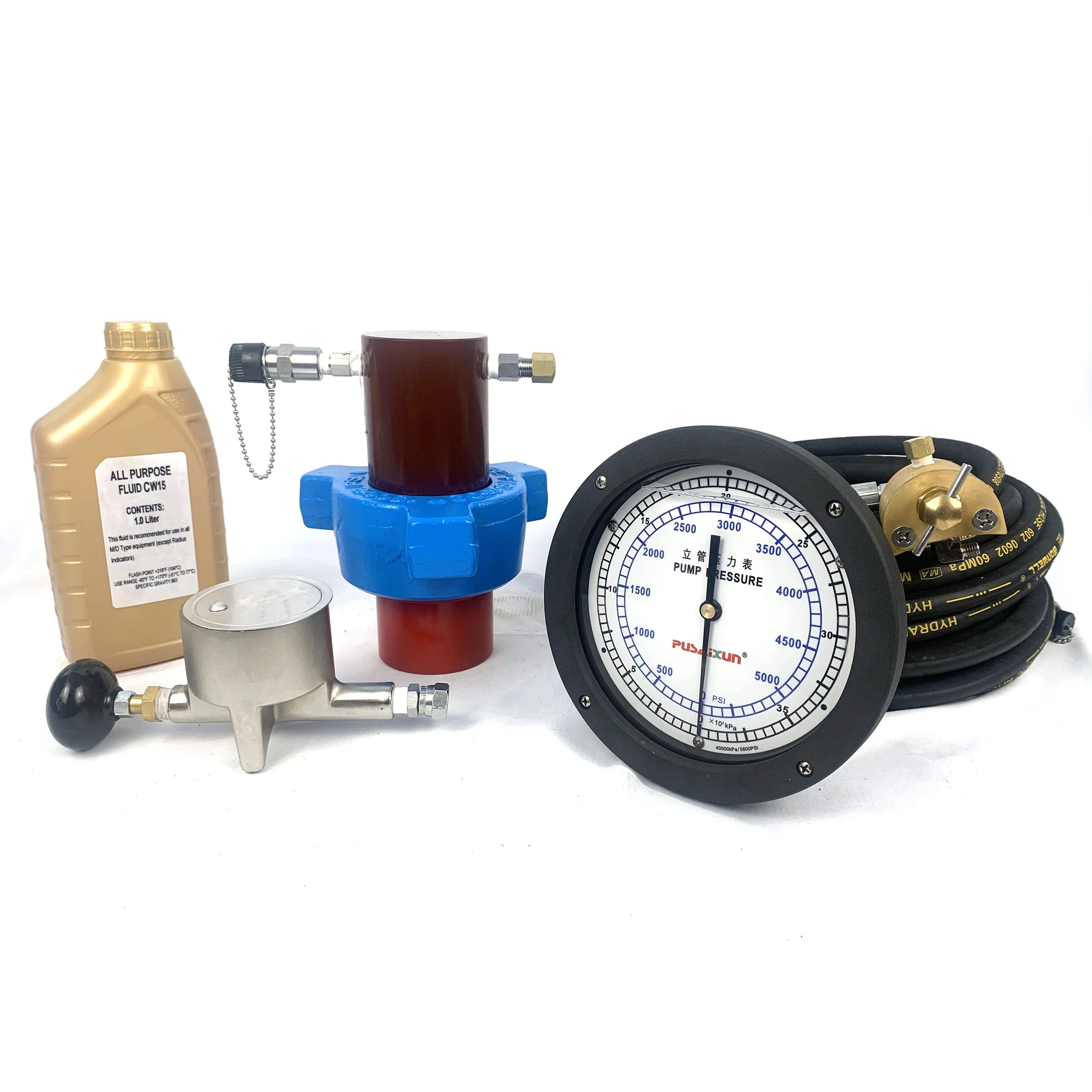
RIGCHINA Stand Pipe Gauges provide a quick, accurate display of pump pressure. Main applications are for standpipes and to be mounted on mud pumps. This style of gauge has been in service for many years and has proven to be a tough, dependable and reliable way to monitor pump pressure.

We provide hydraulic components & repair services for industrial applications like paper mills, saw mills, steel mills, recycling plants, oil & gas applications and mobile applications, including construction, utility, mining, agricultural and marine equipment. This includes hydraulic pumps, motors, valves, servo/prop valves, PTOs, cylinders & parts.

A few years ago, I received a call from a contractor asking for help mitigating a situation with a governmental transport agency in regards to monitoring downhole pressures as they were drilling under a six-lane highway crossing. They were asked to provide details on the drilling fluid they were using and the expected annular pressure while drilling. In order to do this, one must look at the functions of the drilling fluids, the properties of the drilling fluids (like viscosity and solids content), the volume of fluids being pumped, and the rate or speed of drilling.
You may be wondering what this has to do with fluid volumes and downhole pressure? The answer is quite a bit, based on the properties of the fluid being used. The contractor needs to look at the primary properties of the fluid, which are:
The higher the viscosity of the fluid, the higher the pump pressure required and the higher the downhole pressure. As the fluid is designed to suspend and transport cuttings, the amount of fresh fluid being pumped will directly affect the solids content of the fluids being displaced out of the hole. Lastly, the pressure of the drilling fluid, encapsulated by the filter cake against the formation, helps hold the hole open. The filter cake controls the fluid loss with positive pressure; however, it must be controlled in order to not exceed downhole pressure.
Therefore, looking at this example, we know that we need to move 1.02 gallons of soil per linear foot of bore. In order to do this, enough drilling fluids need to be pumped downhole in order to produce a flowable slurry. As mentioned earlier, the viscosity and solids content must be controlled in order to keep the downhole pressure manageable. In fact, a ratio of 2:1 to 3:1 of fluids per gallon of soil is needed in sand, and in clay the ratio may be up to 5:1. For example, if drilling in sand, a 2:1 ratio will be required as a minimum to produce a flowable slurry that will carry the cuttings out of the borehole. In this example, roughly 2-gallons of drilling fluid will need to be pumped per linear foot. As the diameter of the borehole increases, the amount of fluid required increased dramatically. For example, the calculation for a bore done by a 10-inch reamer is:
Without taking into account any pilot or pre-ream, the volume of soils we need to remove is 4.08 gal./ft. Therefore, in sand, we need to pump a minimum of 8.16 gal./ft. of drilling fluids to effectively displace the cuttings.
When pulling a pipe through the borehole, it is essential that the proper volume of slurry is pumped and also that there is sufficient annular space to allow for flow of the slurry. The volume of the fluid will keep the viscosity and solids content low and the slurry flowable. Without creating a flowable slurry, circulation will be lost and pressure in the borehole will increase rapidly, resulting in either a break-off or stuck pipe and/or inadvertent returns at the surface.
This now brings us to downhole pressures. The calculations of recommended downhole pressures are only as good as the geotechnical reports the contractor has. Often the engineering documents will recommend an annular pressure not to be exceeded. There is also software available that can produce this data. It is common that the available geotechnical soil reports were taken from the entry pit and the exit pit or nearby, but not necessarily along the entire planned bore path. Therefore, there can be unknown ground formations along the bore that the contractor may be unaware of unless he or she has drilled in the same area before.
In this equation, 0.052 is a unit conversion factor. It means that hydrostatic pressure (P), the result of the equation, is expressed in units of psi.
The contractor I mentioned at the beginning of this column wanted some assistance to maintain downhole pressure in order to not cause formation damage while drilling under the roadway. The reality is that, in order to do this, the contractor needs to fully understand and ensure the following: the drilling fluid’s functions and properties match the soil type; flow rate requirements are understood; and the speed of the drilling is known and monitored, all while keeping circulation constant.
A small- to medium-sized HDD driller has some options to understand the downhole pressure while drilling. On critical pullbacks, there is special instrumentation that can be installed between the reamer and the pullback string. This instrumentation can provide real-time annular pressure readings. The speed of the drilling and volume of fluids can be regulated to keep pressure consistent and below a pre-determined value. Another option is for the driller to continually measure the mud weight of the fluid returns at the exit pit. The weight of the returns can be an indicator of the downhole pressure. The higher the mud weight, the higher the annular pressure.
Spending the time to understand the fluids required, the volume and speed of drilling, and the resultant annular pressure can make the difference between success and failure. This knowledge results in bores completed on time and on budget. Keep on turning to the right!

A mud/gas separator (poor boy degasser) sizing worksheet will assist drilling personnel with the sizing calculations. The worksheet provides a quick and easy evaluation of most mud/gas separators for a specific well application. A brief discussion of other mud/gas separator considerations is provided, including separator components, testing, materials, and oil-based-mud considerations. This paper reviews and analyzes existing mud/gas separator technology and recommends separator configuration, components, design considerations, and a sizing procedure. A simple method of evaluating mud/gas separation within the separator vessel has been developed as a basis for the sizing procedure.
The mud/gas separator (poor boy degasser) is designed to provide effective separation of the mud and gas circulated from the well by venting the gas and returning the mud to the mud pits. Small amounts of entrained gas can then be handled by a vacuum-type degasser located in the mud pits. The mud/gas separator controls gas cutting during kick situations, during drilling with significant drilled gas in the mud returns, or when trip gas is circulated up.
This paper discusses design considerations for mud/gas separators (poor boy degasser). The purpose of this paper is to allow drilling rig supervisors to evaluate mud/gas separators properly and to upgrade (if required) the separator economically to meet the design criteria outlined in this paper, and to provide office drilling personnel with guidelines for designing mud/gas separators before delivery at the drill-site.
The operating principle of a mud/gas separator is relatively simple. The device is essentially a vertical steel cylindrical body with openings on the top, bottom, and side, as shown in Fig 1. The mud and gas mixture is fed into the separator inlet and directed at a flat steel plate perpendicular to the flow. This impingement plate minimizes the erosion wear on the separator’s internal walls and assists with mud/gas separation. Separation is further assisted as the mud/gas mixture falls over a series of baffles designed to increase the turbulence within the upper section of the vessel. The free gas is then vented through the gas vent line, and mud is returned to the mud tanks.
Operating pressure within the separator is equal to the friction pressure of the free gas venting through the vent line. Fluid is maintained at a specific level (mud leg) within the separator at all times. If the friction pressure of the gas venting through the vent line exceeds the mud-leg hydrostatic pressure within the separator, a blow through condition will result sending a mud/gas mixture to the mud tanks. As one can readily see, the critical point for separator blow through exists when peak gas flow rates are experienced in the separator. Peak gas flow rates should theoretically be experienced when gas initially reaches the separator.
Three types of mud/gas separators commonly are used today: closed bottom, open bottom, and float type. The principle of mud/gas separation within each type of vessel is identical. Differences can be found in the method of maintaining the mud leg, as discussed below.
The closed-bottom separator, as the name implies, is closed at the vessel bottom with the mud return line directed back to the mud tanks, as shown in Fig. 1. Mud leg is maintained in the separator by installation of an inverted V-shaped bend in the mud return line. Fluid level can be adjusted by increasing/decreasing the length of the V-shaped bend.
Commonly called the poor boy,2,3 the open-bottom mud/gas separator is typically mounted on a mud tank or trip tank with the bottom of the separator body submerged in the mud, as shown in Fig. 2. The fluid level (mud leg) in the separator is controlled by adjusting the fluid level in the mud tank or by moving the separator up or down within the tank. Mud-tank height can restrict the maximum mud leg obtainable for open-bottom mud/gas separators.
Fluid level (mud leg) is maintained in a float-type mud/gas separator4 by a float/valve configuration, as shown in Fig. 3. The float opens and closes a valve on the mud return line to maintain the mud-leg level. Valves can be operated by a manual linkage system connected from the float to the valve, or the valve can be air-operated with rig air. Mud-leg height can be controlled by adjusting the float assembly.
There are some inherent problems in the use of float-type mud/gas separators. The manual linkage separator has experienced problems with linkage failure resulting in improper opening or closing of the mud-return-line valve. Air-operated valves fail to function if rig air is lost, resulting in no control of fluid level within the separator. Mud-return-line valves are prone to plug with solids, preventing mud flow-back to the mud pits.
Because of these problems, float-type mud/gas separators are not recommended and a closed-bottom separator is preferred. Open bottom separators are acceptable; however, one should be aware that they are restricted to a maximum mud leg, somewhat lower than the mud-tank height. Although float-type mud/gas separators are strongly discouraged, these separators can be modified easily for disconnection of the float, removal of the valve, and installation of a mud leg in the mud return line.
Table 1 shows a mud/gas separator worksheet to assist with the sizing calculation. The mud/gas separator illustrated in Fig. 4 will be evaluated for sufficient sizing in this paper.
Peak Gas Flow Rate. As discussed previously, the critical time for separator blow-through exists when peak gas flow rates are experienced. Mud/gas separator blow through is defined as inefficient separator operation resulting in a mud/gas mixture returning to the mud tanks through the mud return line.
Friction pressure of the gas venting through the vent line exceeds the mud-leg hydrostatic pressure, resulting in evacuation of fluid from the separator. Friction pressure of the mud through the mud return line is considered negligible because of its short length.
Vessel ID is too small, causing insufficient retention time for the gas to separate efficiently from the mud. This situation is commonly called insufficient’ separator cut.
Vent-Line Friction Pressure. The formula used by this paper to calculate friction pressure of gas through a vent line is derived from the Atkinson-modified Darcy-Weisbach equation.
Note that effective vent-line lengths will be significantly affected by the installation of flame arresters or some auto-igniters. The effect of this additional backpressure should be included in the calculation of vent-line friction pressure.
MudLeg. As previously discussed, mud-leg hydrostatic pressure must exceed vent-line friction pressure to prevent a separator blow through condition. Minimum mud-leg hydrostatic pressure would occur if an oil/gas kick was taken and the mud leg was filled with 0.26 psi/ft oil. 8 This minimum condition mayor may not occur, depending on the well location. Offset well data should be evaluated to establish a minimum mud-leg fluid gradient. For example, the 0.26-psi/ft mud-leg gradient would be considered extremely conservative if dry gas were expected for the sample problem. A more realistic estimate would approach the gradient of whole mud for the dry-gas case. A realistic mud-leg gradient for a gas/water kick would be the gradient of native salt water.
Separator ID. A blow-through condition may exist because a small vessel ID results in insufficient separator cut. Several complicated models exist to describe gas movement within a liquid.9 A simplified approach, taken in this paper, states that the gas migration rate upward within the separator must exceed the liquid velocity downward within the separator to give 100% separator cut and to prevent a separator blow-through condition. Gas migration rate is estimated at 500 ft/hr, or 8.4 ft/min,9 within the separator. This estimation is conservative and more realistic values would be higher; however, the slow gas migration rate serves as a worst-case scenario. Liquid flow rate through the separator can be estimated as 2xqk;for this paper 2×3=6 bbl/min. This factor of two was determined from gas volume at depth calculations (Boyle’s law) using Drilpro ™ for various depths and kick sizes. Correlation of the data shows that the mud flow from the well approaches twice the mud flow into the well (kill rate) for various kick sizes, kill rate, and wellbore geometries. A more accurate determination of mud flow from the well can be incorporated into the design procedure.
Note that a separator cut < 100% frequently exists with mud/gas separators, and under some conditions, is not a major concern. As stated earlier, the mud/gas separator is designed to provide effective separation of mud and gas with small amounts of entrained gas handled by a vacuum degasser located in the mud pits. Therefore, large active pit volumes may tolerate < 100% separator cut.
Sizing Conclusion. Having evaluated sizing criteria for the mud/gas separator (Fig. 4), we may conclude that the separator is sized sufficiently to handle our worst-case kick properly.
The effects of oil-based mud on the operation of the mud/gas separation can significantly affect sizing and design requirements. L These concerns are currently being evaluated. However, some conclusions can be made at this stage.
Gas kicks in oil-based mud that pass through the gas bubble point while being circulated from the well can experience higher Pcmaxand Vcmaxvalues than were calculated for a kick of the same initial pit gain in a water-based mud. This results in higher peak gas flow rates through the separator and thus the requirement for a more stringent separator design.
Gas kicks in oil-based mud that do not pass through the gas bubble point until the gas is downstream of the choke will severely affect mud/gas separator sizing and design. Peak gas flow rates will be extremely high relative to those calculated for water-based mud as outlined in this paper. Additional evaluation of the separator sizing should be completed if these well conditions exist.
Fig. 6 shows other separator components. A minimum 8-in.-ID mud return line is recommended for closed-bottom separators. Smaller lines may encounter problems with solids plugging the line. A larger-ID line would be considered beneficial. The impingement plate should be perpendicular to the separator inlet line and field replaceable.
Closed-bottom mud/gas separators should be designed with a minimum 1-ft sump at the bottom of the vessel. The sump will help prevent solids from settling and plugging the mud-return-line outlet.
A lower manway should be located on the lower part of the separator to permit sump cleanout or unplugging of the mud return line. The manway should be equipped with a replaceable rubber seal to prevent leakage.
The mud/gas separator should be equipped with a valved inlet on the lower section of the vessel to permit mud to be pumped into the separator. Mud can be pumped into the lower section of the separator during operation to decrease the possibility of solids settling in the mud return line. The valved inlet also permits cleaning solids from the lower portion of the separator, especially after separator use.
A siphon breaker or anti-siphon tube may be required to prevent having to siphon mud from the separator into the mud tanks, especially with configurations that require the mud return line to be extended below the separator elevation to allow mud to return to the mud tanks. The siphon breaker is simply an upward-directed open-ended pipe attached to the highest point of the mud return line.
All separators must be built in compliance with the ASME Boiler and Pressure Vessel Code, Sec. VIII, Div. I with all materials meeting requirements of NACE Standard MROJ-75-8412 (1980 Revision). All welding on the vessel must meet ASME requirements.
New mud/gas separators should be hydrostatically tested to 188psi to give a maximum working pressure of 150 psi, as recommended by ASME. Periodic nondestructive testing should include radiographic examination of wall thickness and ultrasound verification of weld continuity. 12 At each initial hookup, every separator should be circulated through with water at the maximum possible flow rate to check for possible leaks in the connections. Frequency of testing should depend on anticipated and historical use of the separator.
Bracing the mud/gas separator has always been a major problem. When gas reaches the surface, separators tend to vibrate and, if not properly supported, can move, resulting in near-catastrophic problems. Thus, it is critical that all mud/gas separators be sufficiently anchored and properly braced to prevent movement of both the separator body and the lines.
Frequently, the situation arises where a mud/gas separator is picked up with the rig contract, and the drilling rig supervisor and engineer must evaluate the suitability of the separator for the well-location. This evaluation typically should be conducted during the rig bid analysis process. If the separator is insufficient or marginal, it may be more economical to upgrade the existing separator to meet the sizing criteria as an alternative to renting or building a suitable one.
Small Vessel ID. We frequently do our calculations and determine that our vessel ID is too small. Reducing the kill rate will improve this situation; e.g., if the kill rate for the previously sized separator were reduced from 3 to 1.5 bbl/min, then from Eq. 7: vL= [(2 x 1.5)/362]/1,029 =2.4 ft/min.
Thus, reducing the kill rate also reduces the liquid velocity rate in the separator, which increases the mud/gas retention time and improves the efficiency of mud/gas separation.
Also note that a gas migration rate of 500 ft/hr (8.4 ft/min) is a worst-case scenario and values could be higher. Therefore, when vessel ID is considered, a marginal separator probably would be sufficient because of this built-in safety factor. Higher gas migration rates may also be used in the sizing procedure, as previously discussed. Fig. 7 shows the effect of kill rate on the calculation of minimum separator ID for different gas migration rates.
Vent-Line Friction Pressure Exceeds Mud-Leg Hydrostatic Pressure.Another area of concern is vent-line friction pressure exceeding mud-leg hydrostatic pressure, Pj> Pml’Several options exist to help alleviate this problem.
Reduce the circulating kill rate. As discussed previously, a reduction in the circulating kill rate may improve a separator’s operation when vessel ID is considered and also when excessive vent-line friction pressures are considered. This reduction in kill rate may be the most economical solution to the sizing concern. For example, if the kill rate for the previously sized separator were reduced from 3 to 1.5 bbl/min, the peak gas flow rate would decrease. Combining Eqs. 1 and 3 and converting, we obtain: (=75.9/1.5=50.6 min and qmax=9,036/50.6=1,443,903 ft31D.
This decrease in peak gas flow rate would significantly decrease the excessive vent-line friction pressure and improve the operation of the separator (Eq. 4). Pj(5.0X10-12 x410x 1,443,903)217.05=0.25 psi.
Increase the mud leg. Another solution may be to increase the height of the mud leg. For example, if we increased the previously sized separator from a 7-ft mud leg to alOft mud leg, the mud-leg hydrostatic pressure should increase (Eq. 6).Pml=lOxO.26=2.6psi. Thus, the mud-leg hydrostatic pressure increased from 1.8 to 2.6 psi, allowing the separator to operate more efficiently.
Fig. 9 shows the effect of mud-leg height on the calculation of mud-leg hydrostatic pressure for different mud-leg gradients. Note that the mud-leg height cannot exceed the separator height. The mud leg may also be restricted by bell-nipple elevation. If the mud leg is higher than the bell nipple, additional surface equipment may be required to permit the separator to operate when drilling with significant gas in the mud returns.
Adjust vent-line bends. As shown in Table 1, the type and number of bends in the vent line significantly affect the effective vent-line length, which in turn affects the calculation for vent-line friction pressure. If we were to replace the targeted T-bends on the previously sized separator with right-rounded bends, the calculations for the effective length (Eq. 5) and vent-line friction pressure (Eq. 4) would change: Le=200+(3X 1)=203 ft and PI=(5.0x 10-12 x203x2,887,806)217.05 =0.5 psi.
Hence, a vent-line friction-pressure decrease from 1.0 to 0.5 psi increases the efficiency of the separator for a given mud leg. In addition, the vent-line friction pressure increases proportionally to the effective length (Fig. 10).
Increase vent-line ID. Increasing the vent-line ID is generally the most expensive alternative but may be the only adjustment possible to increase separator efficiency. Larger-ID vent lines will decrease the vent-line friction-pressure calculation. For the previously sized separator, if an 8.0-in.-ID vent line were used, the calculation for vent-line friction pressure (Eq. 5) would change to PI =(S.Ox10-12 X41OX2,887,806)217.05 =O.Spsi.
Again, a vent-line friction-pressure decrease from 1.0 to 0.5 psi will increase separator efficiency for a given mud leg. Fig. 11 shows the effect of vent-line ID on the calculation of vent-line friction pressure for the previously sized separator.
The principle of mud/gas separation within most commonly used mud/gas separators is identical. Differences can be found in the method of maintaining the mud leg.
A closed-bottom mud/gas separator is the preferred configuration. Open-bottom and float-type separators work well but are subject to limitations and prone to failure.

The discharge pressure of a pump is commonly referred to as head or pressure, but head and pressure are not the same across all liquids. It often causes confusion leading to a miscalculation of the correct pump specification to use.
What is pressure?Pressure is fluid dependent and relative to fluid density. A calculation of the pressure will change according to the fluid’s specific gravity.
Manometers on pumps indicate suction and delivery pressures, and the corresponding differential pressure, which does not take into account the specific gravity of the fluid being pumped meaning any readings provided need to be checked against the fluids specific gravity to calculate the differential pressure being produced.
The absorbed power is the power consumed by the pump during operation at the required duty point. Although a pump may be fitted with a larger motor than is required for the duty, the power absorbed is usually indicated on the pump curve with an intersecting line of where the pump is expected to perform.
The density and pressure directly affect the power absorbed by the motor during operation. The amount of power absorbed by a motor during operation is multiplied by the SG to calculate the power absorbed.
As a pump operates according to the system it is installed in, care will need to be taken to ensure the absorbed power at the highest point of the curve is larger than the density multiplied by the SG.
In the above example, the highest point is 7.5Kw so for water (7.5Kw x 1) max absorbed power will be 7.5Kw, and for a fluid, with a density of 1.3, the maximum absorbed power would be 7.5Kw x 1.3sg = 9.75Kw. A motor greater than 10Kw would be advisable. Read more about why a pump may be fitted with a larger motor.
Head loss refers to the pressure loss (friction) imparted on a fluid as it travels through components in a system. All parts from straight pieces of pipe, to bends, valves, heat exchangers and couplings create different levels of friction loss.
Different angled bends such as 45° bend compared to a 90° will create different levels of loss in a system. Each item has a pressure loss value known as a K factor detailing the losses caused by each part.
Geodetic HeadThis is the physical difference in height between the liquid level and the highest discharge point. This figure can often change when pumping from tanks or pits where the level can fluctuate. There is often a misconception that the Geodetic head is measured from the depth of the suction pipe, but this is not something considered when calculating this but is instead the difference in fluid levels.Pump DeratingAs pump curves are based on water, a correction factor must be applied to a curve to correct it against the liquid being pumped. This is applied when a fluid is more viscous than water, viscosity fluctuates with temperature or if solids are present.
There are several factors which must be considered when correcting pump curves from particle size, temperature, to the properties of a liquid, so it is always better to discuss curve correction with one of our engineers.


 8613371530291